HV Rescue Simple
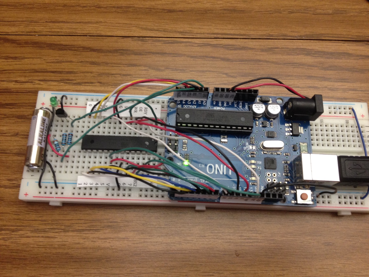
High voltage programming of ATmega328P and other Atmel chips on a breadboard
This procedure shows how to set up an Arduino as a high voltage programmer using a very small number of components: transistor, small inexpensive 12V battery, a paper clip, three resistors, LED, and assorted wire and breadboard. It works with just about any Arduino you may have handy, including Uno or older, Leonardo, Micro, Pro Mini, Nano, Mega2560, etc. The sketch has an easy-to-use menu with simple commands you send to it via Serial Monitor to read or set fuses on the target chip.
If you set this up and become comfortable with using the programmer, you can exploit features of the ATmega328P that you may have not used before, because prior to today most people think they've hopelessly bricked their processors once they set wrong fuse bits. Well, the fuse bits aren't wrong, they are available for use. For example, you can disable the reset pin and start using the reset pin as a general-purpose digital pin. You can disable ISP programming, if you have the need for that. You can set the 128K internal oscillator and experiment with the processor. You can now easily restore factory fuse settings or Uno fuse settings, or whatever fuse settings you want, whenever you have experimented with fuse settings that make your processor unrecoverable via the usual ICSP programming.
I recommend uploading the sketch to the Arduino before connecting the Arduino to the breadboard. The sketch was originally started by Jeff Keyzer for version 2 of his HV Rescue Shield (mightyohm.com/hvrescue2), and I have done extensive reorganization and alterations and simplification, to include giving it a user-friendly menu, changing some of the wiring, making it compatible with various Arduinos, and simplifying the reset circuit for breadboard use.
I recommend becoming familiar with the datasheet for your target processor before using high voltage programming.
Wiring a Pro Mini As HV Programmer
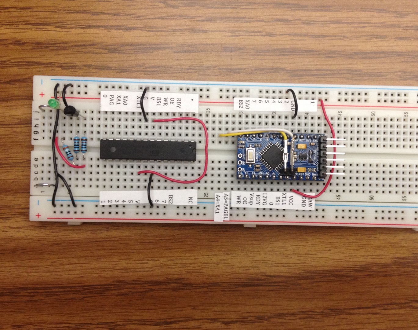
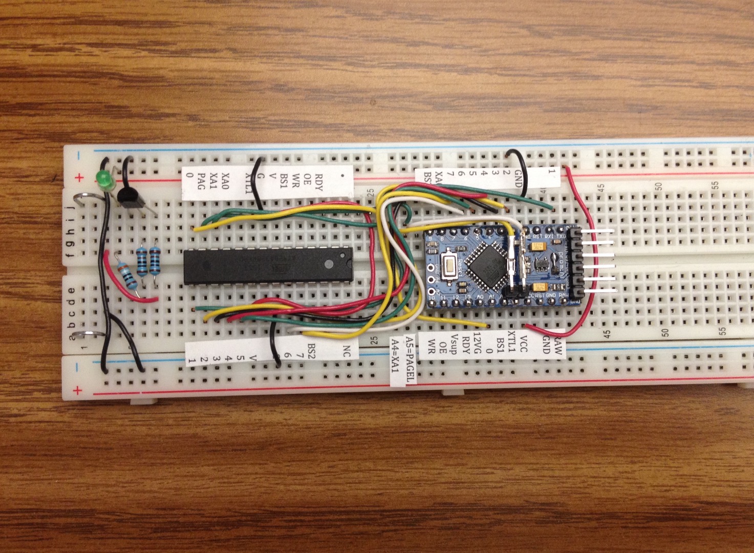
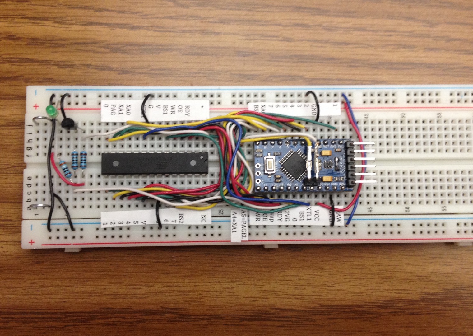
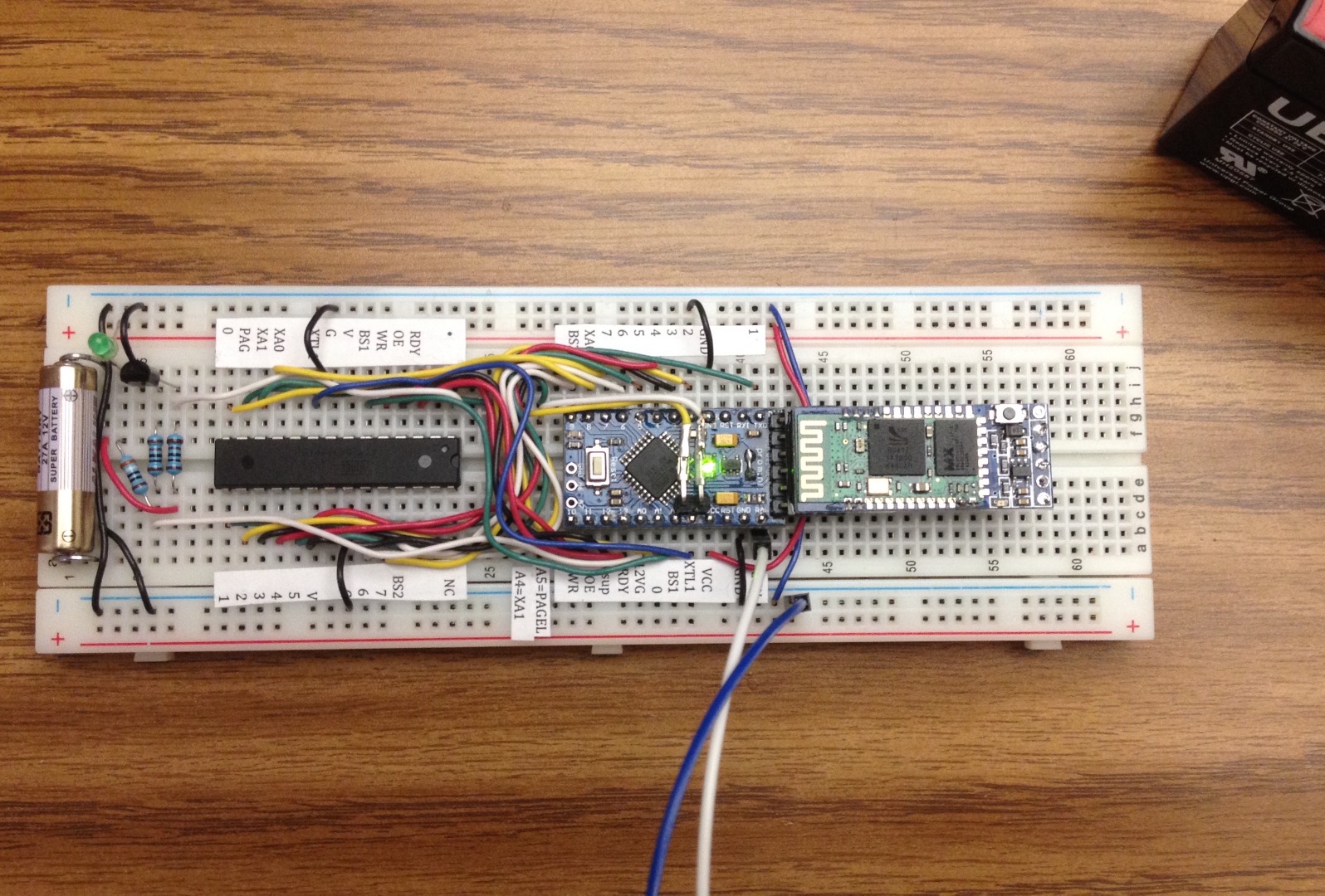
The pictures show the progress I made as I wired the breadboard, and finally it was completed and my FTDI-like adapter connected with the sketch running.
In order to stay organized and make sure the wiring has the best chance of being done right, print out labels that show what each pin is used for on the target chip and on the Arduino. Print them out on regular paper, cut the labels out, and run them through a Xyron Create-a-Sticker machine (which you may find in your better half's scrapbooking tools), or put double-sided tape on them. Then use them and start laying out the breadboard components and wire according to the schematic. Notice the sketch uses digital pins 1-13, and all of the analog pins A0-A5. Digital pin 0, which is the RX pin, is not used.
I have found the small Arduinos such as Pro Mini or Nano result in the neatest breadboard wiring. If you use a Pro Mini or Nano it is also easy to use a multimeter to check continuity of all the connections, to make sure you haven't missed any connections. Note that on Pro Mini the RX pin is marked RXI and TX pin is marked TXO. The TXO pin is pin 1 and RXI pin is pin 0 regardless of how confusing the labeling on the Pro Mini looks. Connect the TX pin to the DATA1 line of the target chip, and do not connect the RX pin to any pin of the target chip.
Use pieces of a paperclip for a battery holder and bend them to get a little spring tension. You can use a 27A or A23 or other similar 12V battery. I have also borrowed a sealed lead acid 12V battery from a UPS. EBay has listings for extremely inexpensive step up converters that are breadboard friendly and can provide 12V. I am contemplating ordering a MT3608 DC-DC Step Up, which costs between $1 and $3 USD postage included. Those modules have the interesting requirement of keeping peak current "no more than TV University." You do not require much 12V current for this, it is just a signal to indicate to the target processor it should enter parallel programming mode, it is not burning anything with high current. If you leave your 12V battery connected to the circuit for a long time, it will drain. So, it would be a good idea to insert it right before programming, and remove it when done.
Notes about the labels I suggest using for keeping your work organized:
Vsup represents the pin 12 of the Arduino supplying operating voltage to the target chip, and that should be connected to the pins labeled V on the target. 12VG represents the pin A0 of the Arduino which controls the 12V switch or gate, and that should be connected to the resistor leading to the base of the transistor.
Using Different Arduinos As HV Programmers
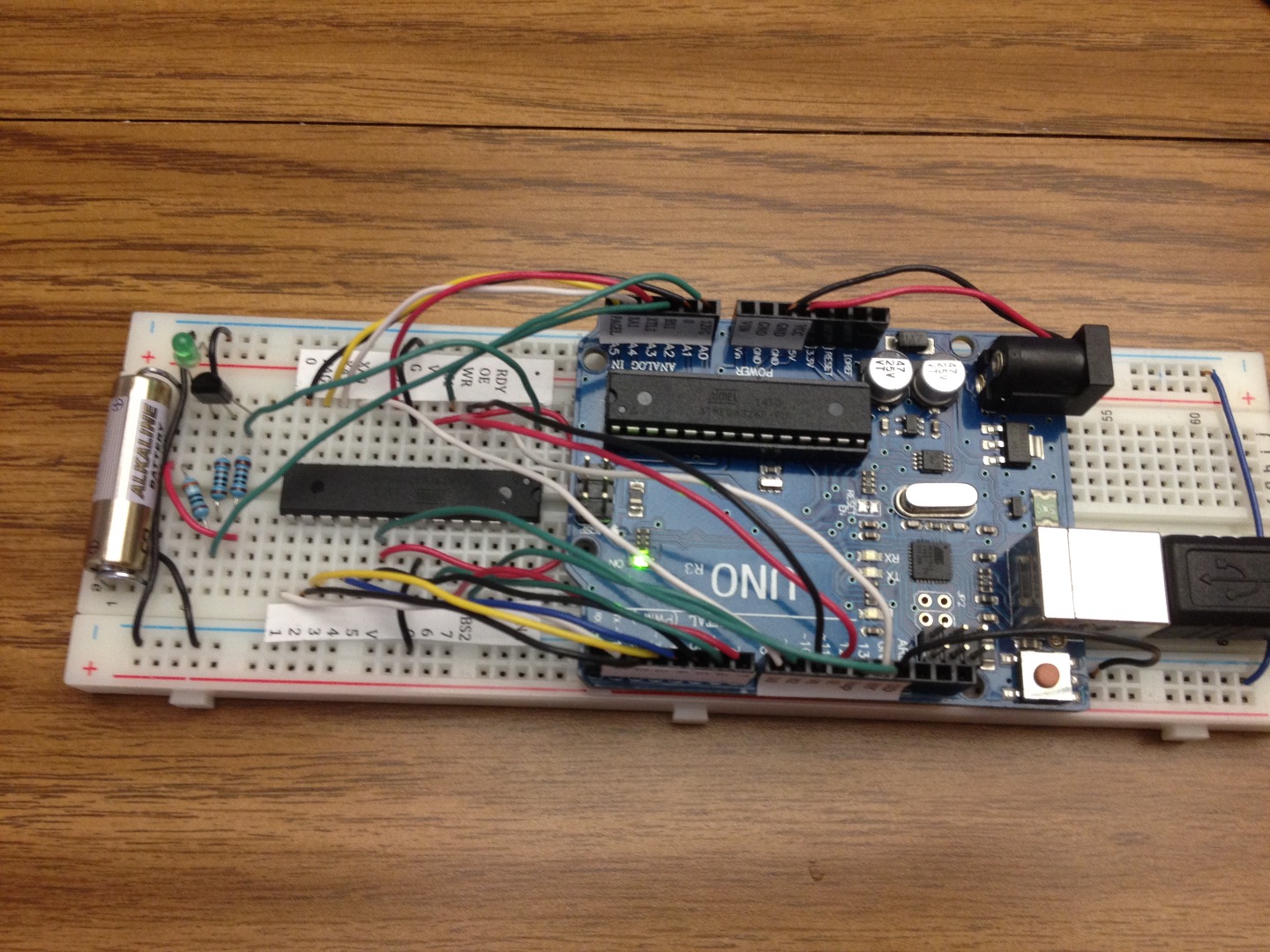
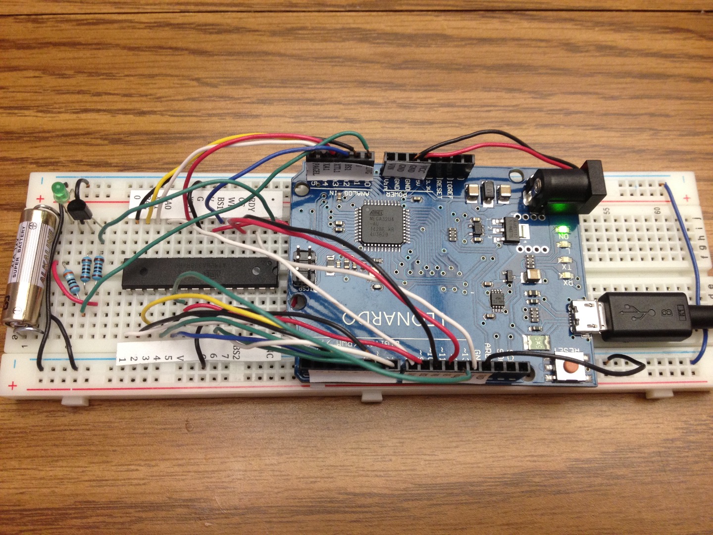
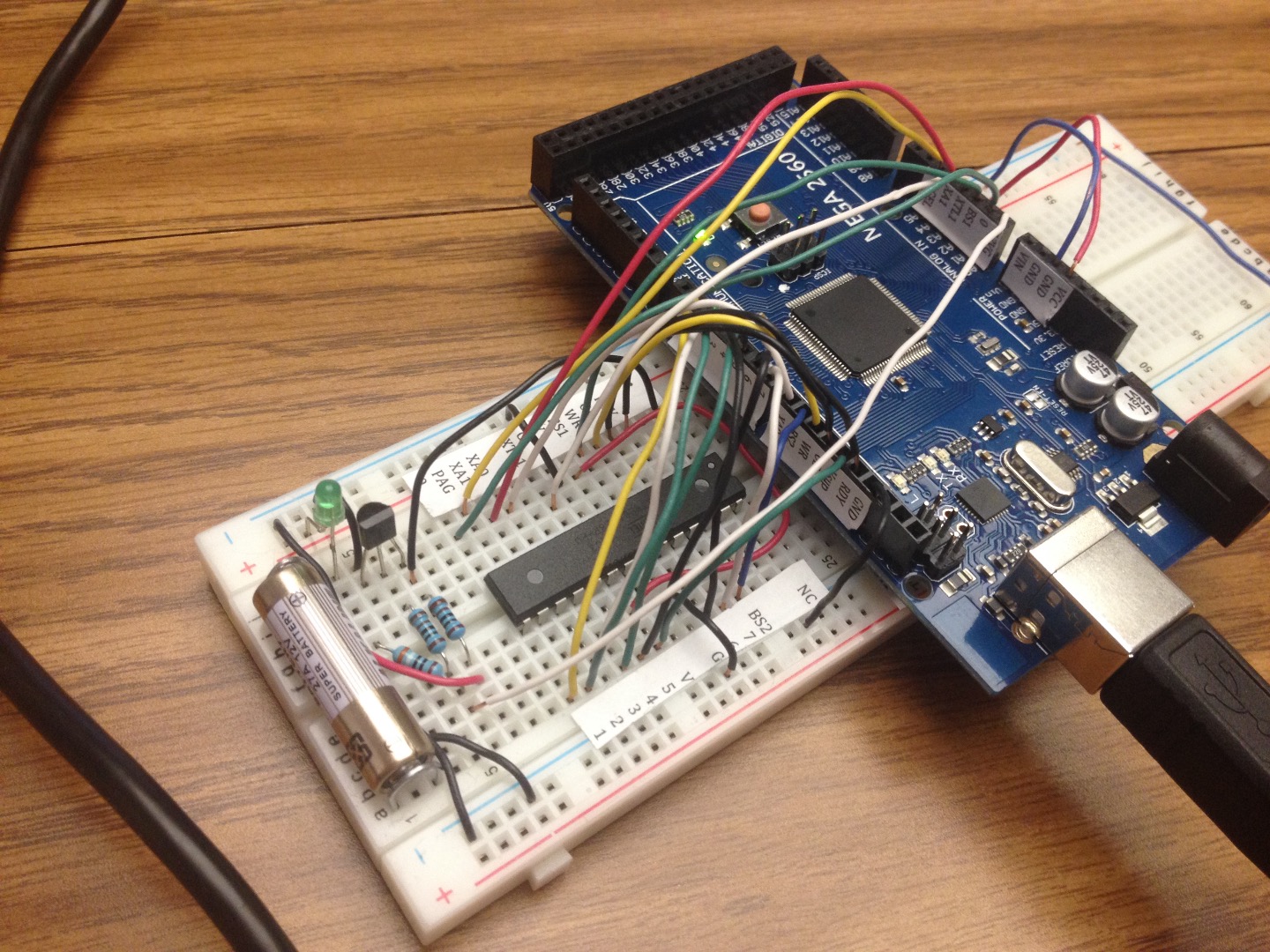
Here are photos of completed wiring for Uno, Leonardo, and Mega2560 setting the fuses on ATmega328P.
Using the Sketch
To use the sketch:
- Attach the Arduino to the computer with the USB cable.
- Insert the 12V battery.
- Open the Serial Monitor and set for 115200 baud.
- The menu should appear and show you the proposed new fuses.
- Type r and click send to read the existing fuses on the target.
- If you like the proposed fuses, type w and click send to write them to the target.
- To set custom fuses, type l, h, or x followed by a number to set the low, high, or extended fuse value, and click send. Repeat for any of the fuses you want to change. Then type w and click send to write them to the target.
- Remove and insert the next processor you want to work with, or remove the 12V battery and disconnect the Arduino from the computer.
If the fuse readings show 02, 00, or FF for all fuse values it is likely the target chip is not inserted properly, wiring is wrong, battery polarity is reversed, or the battery is not producing something near 12V. Check everything with a multimeter, make corrections, and try again.
Other Targets and Miscellaneous Notes
The schematic and sketch also handle setting fuses on ATtiny2313, ATtiny85, ATmega168P, and other targets. I have also used this to set the fuses on an assembled Digispark tiny85 board. Read the sketch and schematic, and especially study the data sheet for your target chip, to figure out the wiring.
If your target is a chip soldered on a board, such as Uno SMD or Nano or something like that, you should temporarily remove the DTR-to-Reset 0.1uF capacitor, the pull-up resistor for the reset pin, and the diode connected to the reset pin (if your board has one). You can put them back when you are done using the HV Rescue procedure.
Some of the pin connections serve dual purposes when programming ATtiny2313. To clarify what you see in the schematic, the BS1 pin of the Arduino (analog pin A2), goes to PD4 physical pin 8 on the ATtiny2313 and you leave the Arduino PAGEL pin of the Arduino (digital pin 5) unconnected. The PAGEL signals are sent through the BS1 pin by the sketch. The same thing is true of XA1 pin. The XA1 pin of the Arduino (analog pin A4), goes to PD6 physical pin 11 on the ATtiny2313 and you leave the Arduino BS2 pin of the Arduino (digital pin 9) unconnected. The BS2 signals are sent through the XA1 pin by the sketch.
How does the transistor switch on and off 12V to the reset pin of the target chip? Explanation: 12V is applied to the target chip reset pin through a resistor. So, you could say normally 12V is just applied to the reset pin. The transistor is switched on when it receives a 5V high signal from one of the Arduino pins, through the resistor to the base pin of the transistor. When the transistor is switched on, it conducts between the collector and emitter pins. This shorts to ground the 12V which was going to the reset pin, making it effectively 0V at the reset pin. When the Arduino sends 0V low signal to the base of the transistor, it switches off the transistor, and it no longer conducts, essentially taking it out of the circuit. 12V is once again applied to the target chip reset pin.
This is called inverting, because a low signal is applied to make an output go high, and a high signal is applied to make the output go low.
The resistor attached to the base of the transistor is a current limiting resistor. The resistor attached to the 12V battery does double duty: it is a current limiting resistor when the transistor is switched on and shorting the 12V to ground, and it is a pull-up resistor for the reset pin when the transistor is switched off.
The programming happens very quickly, but if you insert a delay(5000); in the sketch before the two lines "digitalWrite(RST, HIGH); // exit programming mode", it would allow you enough time to observe with a multimeter the voltage at the reset pin of the target chip, and see that it goes to 12V during reading or writing of the fuses.
Links
https://www.instructables.com/id/How-to-unlock-Digispark-ATtiny85-and-convert-it-to/?ALLSTEPS
http://eleccelerator.com/fusecalc/fusecalc.php?chip=atmega328p&LOW=62&HIGH=D9&EXTENDED=FF&LOCKBIT=FF
http://www.ermicro.com/blog/?p=423
http://www.gammon.com.au/forum/?id=12898
http://mightyohm.com/blog/products/hv-rescue-shield-2-x/
https://arduinodiy.wordpress.com/2015/05/16/high-voltage-programmingunbricking-for-attiny/
https://www.instructables.com/id/How-to-change-fuse-bits-of-AVR-Atmega328p-8bit-mic/