HOW TO CREATE a 3D BALL BEARING IN 3D MODELLING SOFTWARE
by Simran Khuntia in Circuits > Soldering
464 Views, 1 Favorites, 0 Comments
HOW TO CREATE a 3D BALL BEARING IN 3D MODELLING SOFTWARE
.png)
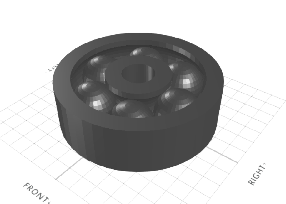
In this tutorial article, we will 3D design a ball bearing. The 3D modelling software that we are using is SelfCAD. The tools of SelfCAD that we will utilise are the 3D Shapes, 3D sketch, revolve, Move, copy offsets tools, etc. We will begin by 3D designing a rectangle sketch and developing it. By figuring out approaches to 3D design this ball bearing, you will get to know how to control various tools of SelfCAD.
You can also go through our other such articles such as how to design a 3D T-shaped pipe by visiting our website.
How about we start!
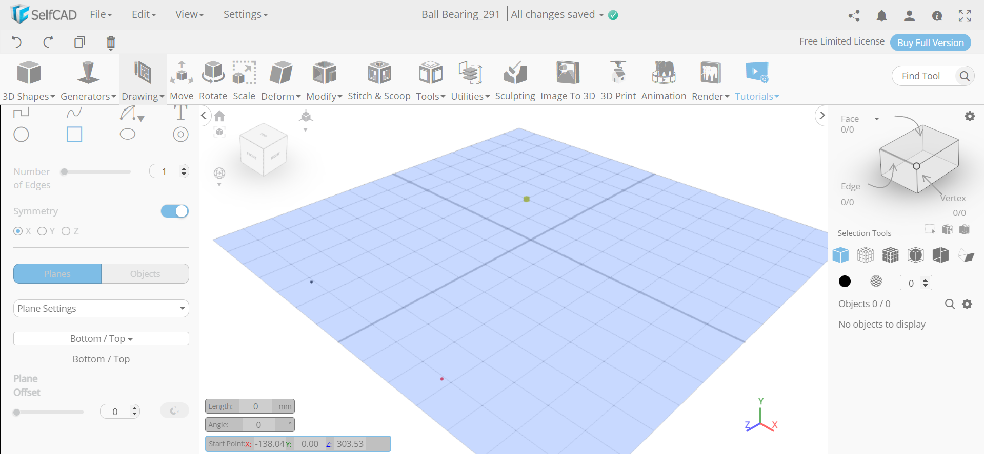
Go to 3D Sketch and Choose Rectangle Sketch
.png)
First of all, from the drawing category select the 3D sketch. Then from the panel, choose the rectangle sketch. Set symmetry to true and snap to grid vertices.
Draw Two Rectangles and a Central Circle
.png)
.png)
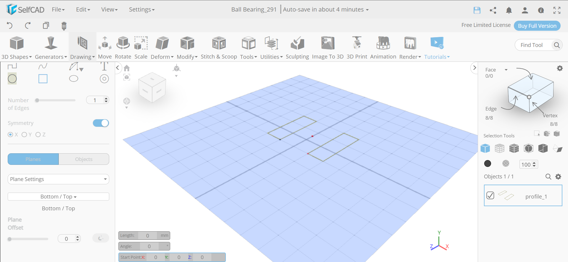
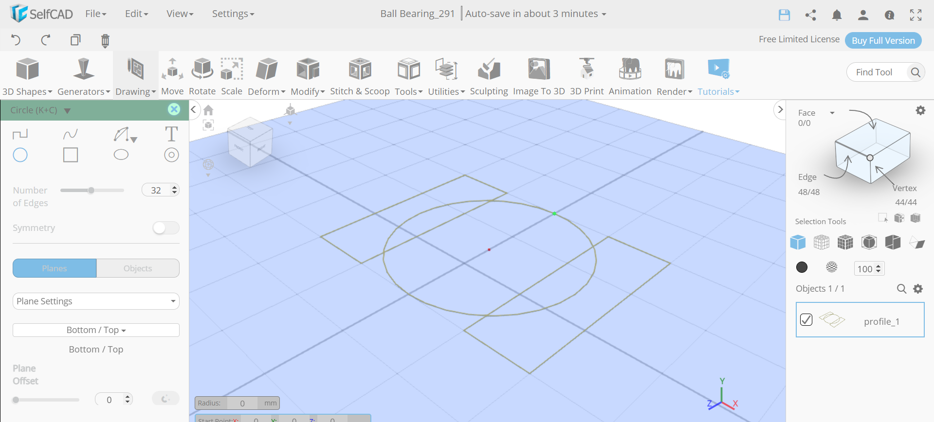
Next, we will draw the rectangle involving three square tiles within it. Then choose the circle sketch and set symmetry to false. After that, draw a circle in the centre as shown in the image.
Delete the Intersecting Edges
.png)
.png)
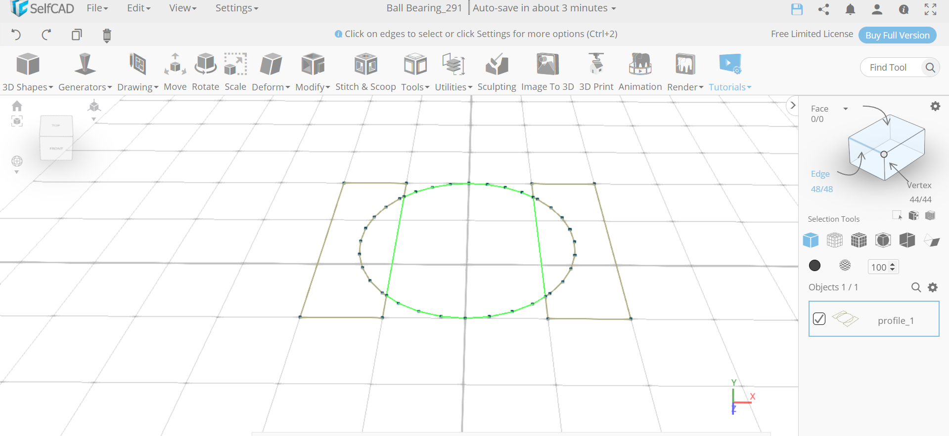
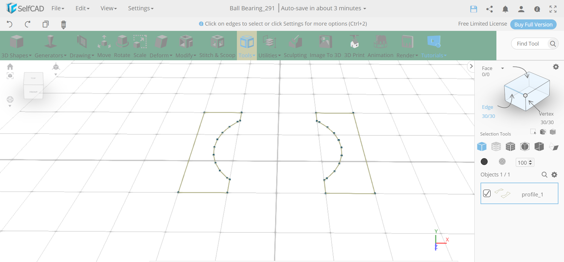
Now, opt for edge selection and select the intersecting edge as shown in the image. Then delete the edges that we selected.
Revolve the Object and Then Rotate It
.png)
.png)
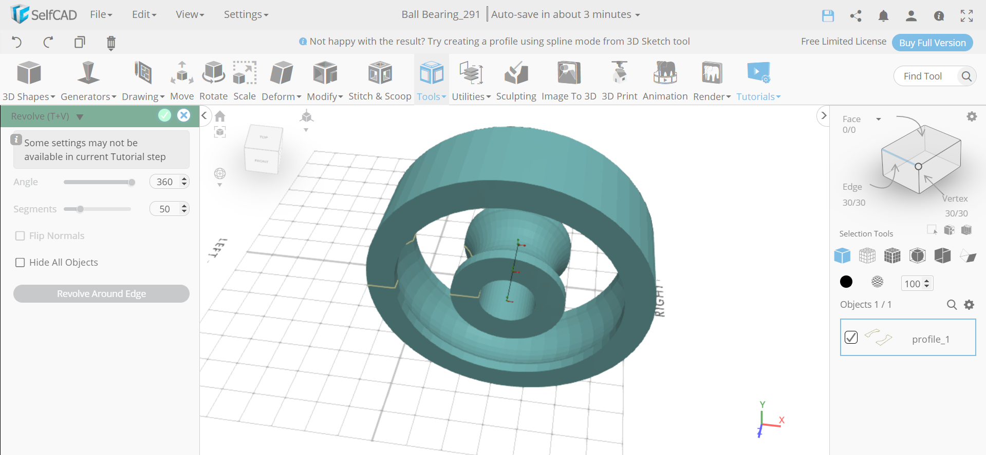
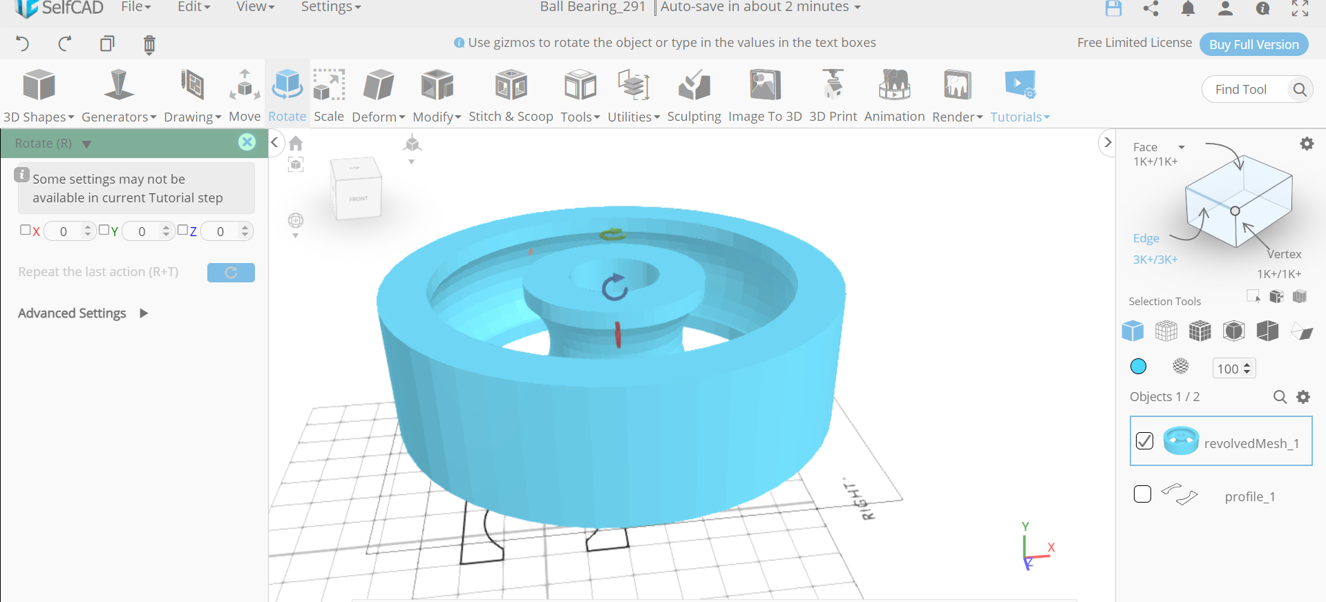
Next, from the tools category, select the revolve option. Set segments to 50. Then select the rotate tool and set x to 90.
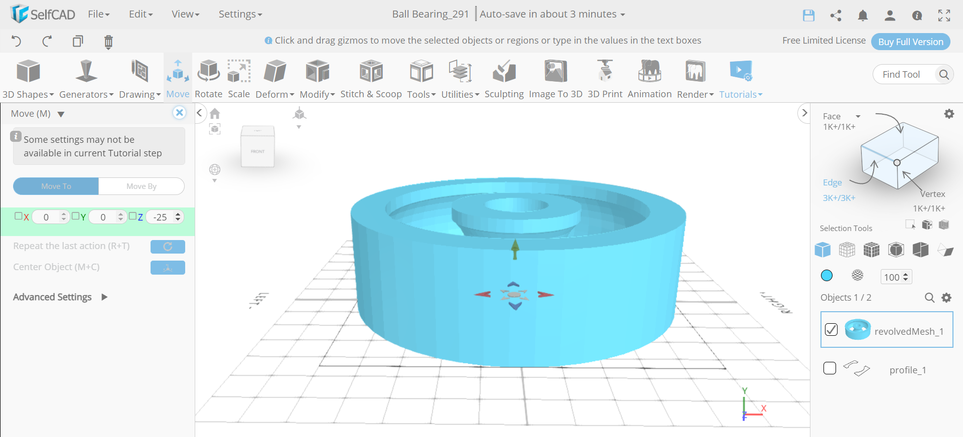
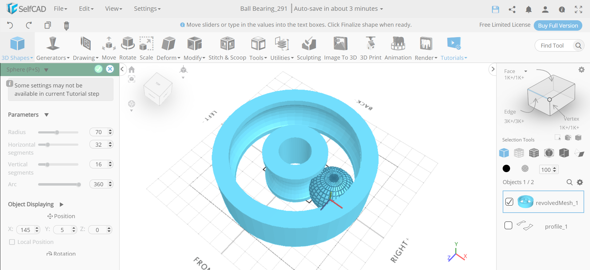
Bring the Object to Origin and Insert a P
.png)
.png)
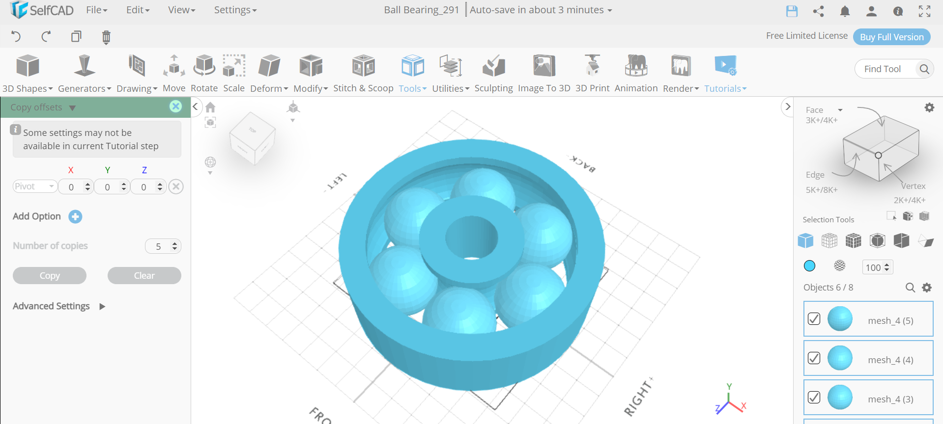
Create Copies of the Sphere and Make Them a Group
.png)
Next, from the tools category select the copy offset option. Set operation to pivot and number of copies to 5. Then create copies. After that, go to the edit menu and make all the spheres a group.
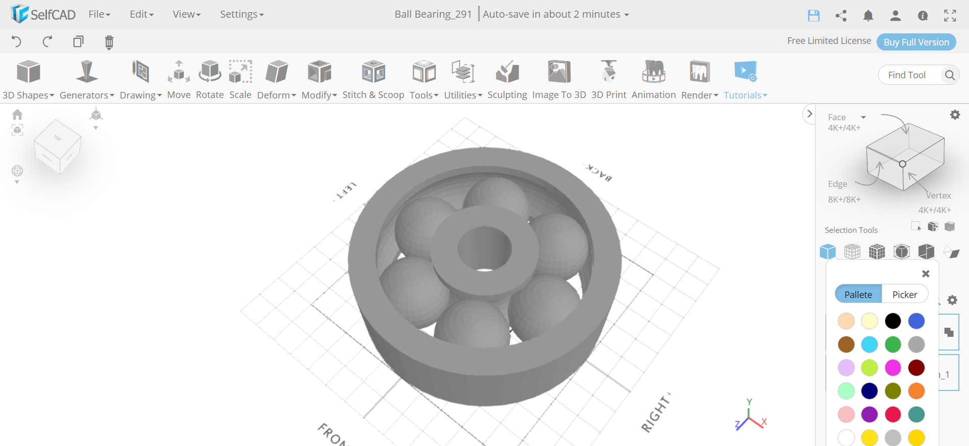
Colour the Objects and Add Materials to It
.png)
.png)
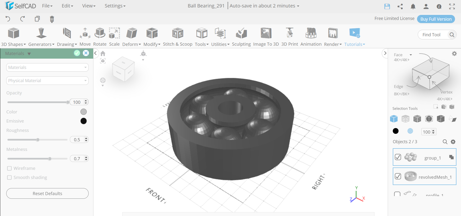
Now, we will select revolvemesh_1 and select the colour picker option. Change the colour of the selected object to silver. Then from the right panels choose materials. Set material type to physical material and metalness to 0.7.
Delete the Sketch Profile
Next, click on the inverse selection option and delete the selected profile.
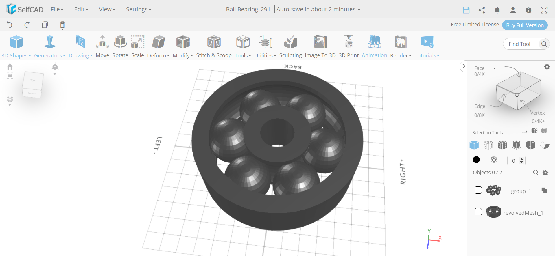
CONCLUSION: THEREFORE, WE HAVE CREATED a 3D BALL BEARING USING SelfCAD
.png)
We have 3D designed the Ball bearing in SelfCAD and we have additionally demonstrated the way that you can utilise the different tools of SelfCAD like edge selection and 3D shapes as well as other fundamental tools like scale, move, and revolve. Every one of the 3D models made in SelfCAD are 3D printable as they leave no numerical misuses that could make approaches hard to print. Once wrapped up with the design cycle, you can use the in-fabricated slicer of SelfCAD to deliver the G-Code record that you can ship off your 3D printer.