HOMEMADE RACING SIM (ACCELERATOR | BRAKE | STEERING)
by HertzandMadden in Design > Game Design
3240 Views, 10 Favorites, 0 Comments
HOMEMADE RACING SIM (ACCELERATOR | BRAKE | STEERING)


Hello everyone!
So we are all locked up inside our houses and looking for things to do during the quarantine.
I personally love to drive and the lockdown has restricted my driving to within the parking lot of my apartment.
My brother bought me the official F1 2019 game during the initial stages of the lockdown in 2020 and I played it for a while only to get bored of driving using a keyboard.
I started playing Need For Speed Most Wanted 2012 recently and enjoyed it for a while before getting bored of it for the same reason. I wanted something more exciting and realistic.
So I went on Amazon and searched for a racing simulator with foot pedals, a steering wheel and a gear shifter.
I was quite surprised to see that the Logitech G29 cost around 30,000 INR! I immediately closed the browser tab and went on Robu.in to order some components to make a cheap racing simulator by myself.
After looking at the unreasonable prices of acrylic sheets online, I decided to build the entire project off corrugated cardboard sheets that I acquired from the boxes of household electronics.
The video tutorials for the foot pedals and steering wheel can be found on our youtube channel!
Steering wheel: Watch here!
Foot pedals: Watch here!
Let's quickly go over the supplies required and get started!
GATHER THE SUPPLIES


Electronics and parts:
> Male berg strips: Buy here.
> Multi-strand wires: Buy here.
> Dupont jumper wires: Buy here.
> 10K Rotary potentiometer: Buy here.
> Big tactile pushbutton with cap: Buy here.
> Small tactile pushbuttons: Buy here.
> PS2 joystick modules: Buy here.
> Servo horns: Buy here.
> Servo control rods: Buy here.
> 6mm potentiometer knob: Buy here.
Tools and consumables:
> 3mm heat shrink tube: Buy here.
> 4mm heat shrink tube: Buy here.
> 5mm heat shrink tube: Buy here.
> Soldering station: Buy here.
> Digital multimeter: Buy here.
> Hot glue gun: Buy here.
> Scissors: Buy here.
> Nose pliers: Buy here.
> X-Acto knife: Buy here.
> Fine file set: Buy here.
> Precision screwdriver set: Buy here.
> 3mm rubber bands: Buy here.
Adhesives:
> Packing tape: Buy here.
> Heavy-duty double-sided tape: Buy here.
> General purpose double-sided tape: Buy here.
> Electrical insulation tapes: Buy here.
> General purpose adhesive: Buy here.
> Superglue: Buy here.
> White glue sticks: Buy here.
INTRODUCTION TO THE CONTROLLER
.JPG)
.JPG)
.JPG)
.jpg)


A typical game controller consists of two joysticks, namely, the left and right stick.
These joysticks are basically two rotary 10K potentiometers at right angles to each other that control the values along the horizontal(X) and vertical(Y) axis.
So, we have 2 potentiometers(Right stick) that we are interested in using for the racing simulator.
We will be using only the right stick in this project, the left stick can be used to add a manual handbrake and a clutch in the future.
These potentiometers share a common ground and +5V.
We can determine the GND pins of the potentiometers by either tracing the path of the GND battery terminal or with the help of the continuity test function on a multimeter.
Moving to the functions on the steering wheel, we will be using four pushbuttons.
Two will be used to shift gears and the other two can be used as you will. I will be using them as the handbrake and nitrous buttons.
The buttons on the joystick do share common ground but the two shoulder buttons don't share a common ground with the other pins on the PCB.
So, in conclusion, we will be using 9 pins as following:
A pin for common ground
A pin for common VCC
A pin for the common terminal of the shoulder buttons.
Two pins for the shoulder buttons
Two pins for the thumb buttons
A pin for the right stick's horizontal(X) axis
A pin for the right stick's vertical(Y) axis
PREPARE THE CONTROLLER | Part 1: Initial Operations


Let's perform the initial operations on the controller.
1) Use an appropriate screwdriver to unscrew the screws holding the back cover in place. There's a good chance there's a screw hidden under the quality control sticker. Make sure you get that too!
2) Carefully unplug the battery connector.
3) Remove the battery to reveal useful pins on the PCB.
4) Breakaway 12 pins from a male berg strip.
5) Use some heavy-duty double-sided tape to hold the berg strip down for soldering.
PREPARE THE CONTROLLER | Part 2: Bridging the Pins on the PCB With the Berg Strip


Make the connections as following:
1) Common ground on the PCB -> Pin 1 on the berg strip
2) Common pin of the shoulder pushbuttons on the PCB -> Pin 2 on the berg strip
3) Right shoulder button (Gear shifter) -> Pin 3
4) Left shoulder button (Gear shifter) -> Pin 4
5) Right stick button (Nitrous/Camera) -> Pin 5
6) Left stick button (Nitrous/Camera) -> Pin 6
7) Right stick vertical axis potentiometer (Acceleration and deceleration) -> Pin 7
8) Right stick horizontal axis potentiometer (Steer left and right) -> Pin 8
9) Left stick horizontal axis potentiometer (Not used, cab be used for a clutch) -> Pin 9
10) Left stick vertical axis potentiometer (Not used, can be used for a manual handbrake) -> Pin 10
11) Common +5V on the PCB -> Pin 11
12) Common +5V on the PCB -> Pin 12
Add a 3 pin header to any common ground on the PCB to serve as ground pins for adding additional buttons in the future.
PREPARE THE FOOT PEDALS | Part 1: Building a Sturdy Platform


I was in possession of some 2 by 3, 18mm thick plywood strips.
I made a right angle butt joint along the length of the strips.
I used plywood grade adhesive and let it dry for 24 hours.
PREPARE THE FOOT PEDALS | Part 2: Designing the Foot Pedals
.jpg)
.jpg)
.jpg)
.jpg)
.jpg)
.jpg)
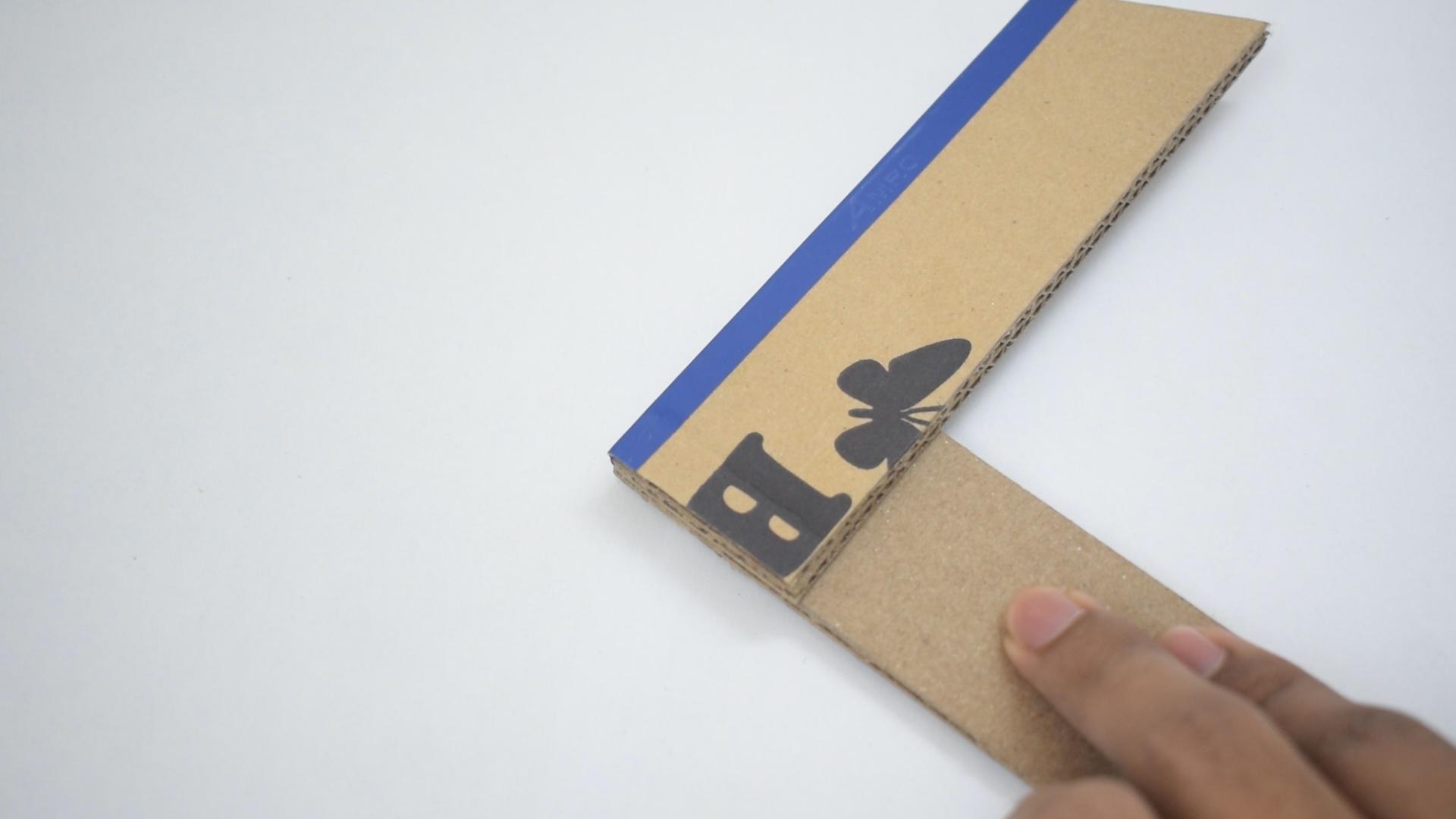
I used 3mm corrugated cardboard that I acquired from various packing boxes of some electrical products.
Take a blank of 28 X 20 cm cardboard.
Mark a line 12cm and 24cm above the datum along the breadth of the cardboard.
Mark a line 4cm and 16cm above the datum along the length of the cardboard.
PREPARE THE FOOT PEDALS | Part 3: Cuts and Creases
.jpg)
.jpg)
.jpg)
.jpg)
.jpg)
Cut off the unwanted pieces.
Crease the line 12 cm above the datum to form a hinge for the foot pedal.
Crease the lines along the length to form the guide rails for the foot pedal.
Crease the line 24 cm above the datum to form the back face of the foot pedal's base.
PREPARE THE FOOT PEDALS | Part 4: Forming
.jpg)
.jpg)
.jpg)
.jpg)

Bend the guide rails towards the base.
Bend the backplate towards the base.
Use some general-purpose adhesive to form right angles between the base of the foot pedal and guide rails.
PREPARE THE FOOT PEDALS | Part 5: Adding the Stopper and Making the Hinge


Use a bottle cap of about a centimetre in height to serve as the stopper for our foot pedal.
Paste a strip of packing tape along the crease with the foot pedal's underside facing the sky.
Move the foot pedal towards the base to have its upperside face the sky.
Paste a strip of packing tape along the crease.
PREPARE THE FOOT PEDALS | Part 6: Reinforcing and Adding the Rubber Band

.jpg)


Cover the foot pedal with packing tape.
Stick some popsicle sticks on the backside of the foot pedal using some superglue.
Glue one end of the rubber band to the end of the centre popsicle stick and add some hot glue to strengthen the joint.
PREPARE THE FOOT PEDALS | Part 7: Mounting


Use double-sided tape on the backside of the foot pedal's base.
Place the foot pedal and the plywood platform on a level surface.
Slide the foot pedal to the platform's front face and gently apply some force to stick it to the platform.
Stick a servo control horn to the top right corner of the foot pedal using some hot glue.
Prepare a link with some servo control rods and insert one end into the control horn.
Insert the other end to the joystick and place it on top of the platform such that the foot pedal is in its initial state along with the joystick being centred.
Use some hot glue to secure the joystick in place.
Stick the rubber band to the plywood using some superglue.
PREPARE THE FOOT PEDALS | Part 8: Making the Extension Cable


The controller will be placed on top of the table. So, we will need to make an extension cable to connect the foot pedals to the controller.
The cable will consist of three wires:
GND
SIGNAL
VCC
Connect the GND of the accelerator's potentiometer to the VCC of the brake's potentiometer.
Connect the VCC of the accelerator's potentiometer to the GND of the brake's potentiometer.
Connect both the signals of the potentiometer together.
Use some female jumper wires and solder them to the common power wires and signal wires of the potentiometers.
Doing so will combine both the potentiometers to work in one axis of the joystick. Pressing down on the accelerator will act as pulling down/pushing up on the right stick and pressing down on the brake will act as the opposite of pushing down on the accelerator.
Use three wires of required lengths and solder a 3 pin male header to one end and solder female jumper wires to the other.
TESTING THE FOOT PEDALS


1) Use the extension cable to connect the foot pedals to the controller.
Power wire 1: COMMON GROUND PIN on the berg strip
Power wire 2: COMMON VCC PIN on the berg strip
Signal wire: PIN 7 (Right stick's vertical axis potentiometer)
2) Open up the control panel on your PC and navigate to devices and printers.
3) Locate your controller and right-click on it, click on "game controller settings" and click on "properties".
4) Press down on the foot pedals to see if the Y ROTATION bar moves left and right.
NOTE:
Pressing down fully on the accelerator must move the Y rotation bar fully to the left if you want it to mimic " RS UP" (Right stick up)
Pressing down fully on the decelerator/brake must move the Y rotation bar fully to the right if you want it to mimic "RS DOWN" (Right stick down)
If the bars move in the opposite directions, simply swap the power connections of the foot pedals.
This step is not absolutely necessary unless the game you wish to play doesn't allow remapping of the controller settings.
PREPARE THE WHEELBASE: Part 1: Design and Fabrication


Design the wheelbase using your creativity.
Just make sure to keep the frontal width well shorter than the steering wheel's width to avoid contact between the wheelbase and your hands while using the wheel.
This can be overcome by using a longer potentiometer knob.
Mark the centre of the wheelbase's face and make a small hole with a pointy object like a screwdriver.
Enlarge the hole to approximately 6mm using a round file.
Make another hole large enough above the centre hole to accommodate the switches' cable.
PREPARE THE WHEEL BASE: Part 2: Installing the Potentiometer


Solder wires of suitable lengths to the potentiometer.
Solder female jumper wires to the ends of the wires.
Screw the potentiometer into its hole and use the washer and nut provided with the potentiometer to secure it in place.
PREPARE THE STEERING WHEEL: Part 1: Making the Handles


.jpg)
.jpg)
.jpg)
.jpg)
.jpg)
Take a blank of 15cm X 8cm corrugated cardboard.
Mark the centre line along the length and crease it.
Fold and glue the faces onto each other.
Provide some personality to the handles as you wish!
PREPARE THE STEERING WHEEL: Part 2: Making the Spokes
.jpg)
.jpg)
.jpg)
.jpg)
.jpg)
Take a blank of 16cm X 30cm corrugated cardboard.
Divide it into 2 halves along the length.
Mark the centre lines along the lengths on the two halves obtained and crease them.
Fold and glue the faces onto each other.
PREPARE THE STEERING WHEEL: Part 3: Adding the Potentiometer Knob and Reinforcements
.jpg)
.jpg)
.jpg)
.jpg)
.jpg)
.jpg)
Mark the centre point on one of the spokes.
Stick the potentiometer knob to the spoke using some superglue. Follow up with a nice bead of hot glue around the knob's circumference if needed.
Use some popsicle sticks to provide rigidity to the spoke.
PREPARE THE STEERING WHEEL: Part 4: Joining the Parts
.jpg)
.jpg)
.jpg)
.jpg)
.jpg)
.jpg)
.jpg)
.jpg)
Mate the handles to the lower spoke.
Attach the upper spoke to the handles.
Attach the centre spoke to the upper and lower spokes.
I used general-purpose glue to carry out the operations.
PREPARE THE STEERING WHEEL: Part 5: Adding the Pushbuttons and Paddle Shifters


Make a small hole to accommodate three multi-strand wires.
Use some super glue and stick a big square tactile pushbutton to the right-side handle.
Make a square hole on the left-side handle to accommodate a big square tactile pushbutton.
Stick small pushbuttons towards the outside ends of the popsicle sticks.
Cut two cardboard strips approximately 5cm long by 2cm wide.
Make a crease 1cm away from the end.
Stick the smaller portion of the strip to the spoke such that pushing on the paddle click the pushbutton.
I will be using the big pushbuttons to activate nitrous and apply the handbrake.
I will use the small pushbuttons to shift gears.
PREPARE THE STEERING WHEEL: Part 6: Connecting the Pushbuttons


Use multistrand wires to connect any two internally connected pins of the big tactile pushbuttons.
This will be the common wire for the pushbuttons.
Do the same for the small pushbuttons.
Now use multi-strand wires and solder them to the outputs of the big pushbuttons.
Do the same for the small pushbuttons.
Use wires of different colours for the two sets of pushbuttons to easily differentiate between the two.
PREPARE THE STEERING WHEEL: Part 7: Finishing Up


We will be left with a wire for the common terminal of the big pushbuttons, a wire for the common terminals of the small pushbuttons and four wires for the output terminals of the pushbuttons.
The big pushbuttons' common wire can be directly soldered to the ground pin of the wheelbase's potentiometer.
Solder female jumper wires to the ends of the five wires.
Add caps of your desired colours to the pushbuttons!
TESTING THE STEERING WHEEL AND BUTTONS!


Connect the wheelbase's potentiometer to the controller as such:
GND -> GND pin on the bergstrip
Singal -> Right stick X axis pin on the bergstrip
VCC -> +5v pin on the bergstrip
Open up the game controller properties and check to see if the potentiometer is centred.
Now pass the cable through the hole and couple the steering wheel with the wheelbase.
NOTE:
Moving the steering wheel fully to the left must move the X-axis bar fully to the left if you want it to mimic "RS LEFT" (Right stick left)
Moving the steering wheel fully to the right must move the X-axis bar fully to the right if you want it to mimic "RS RIGHT" (Right stick right)
If the bars move in the opposite directions, simply swap the power connections of the foot pedals.
This step is not absolutely necessary unless the game you wish to play doesn't allow remapping of the controller settings.
GO CRAZY!!!

.jpg)
.jpg)
Launch your favourite racing game and go to the controller settings to remap the buttons.
I tested the racing simulator on F1 2019, Forza Horizon 4 and Need for Speed Most Wanted 2012 and I had a blast!!!
The foot pedals were very responsive and using the onboard button on the steering wheel to activate DRS and nitrous made me happier than anything else in the world!
Even the paddle shifters felt very satisfying to use due to their tactile feedback!
For just 1/100th of the cost of a commercial racing simulator like the Logitech G29, this homemade simulator gave me immense pleasure playing with it.
In conclusion, this dead simple project was very fun to work on and I will definitely be working on upgraded versions of the same, maybe a fully 3D printed version, a solid metal built version, and what not!
I assure you will have a very good time recreating this project and an even better one while racing with it.
I hope by doing so, you would suppress your urge to go outside in this chaotic time.
Stay home and stay safe and keep racing!!!