HICTOP X-axis Belt Clamp Replacement
by Gammawave in Workshop > Repair
425 Views, 0 Favorites, 0 Comments
HICTOP X-axis Belt Clamp Replacement
This is an instruct-able born out of necessity.
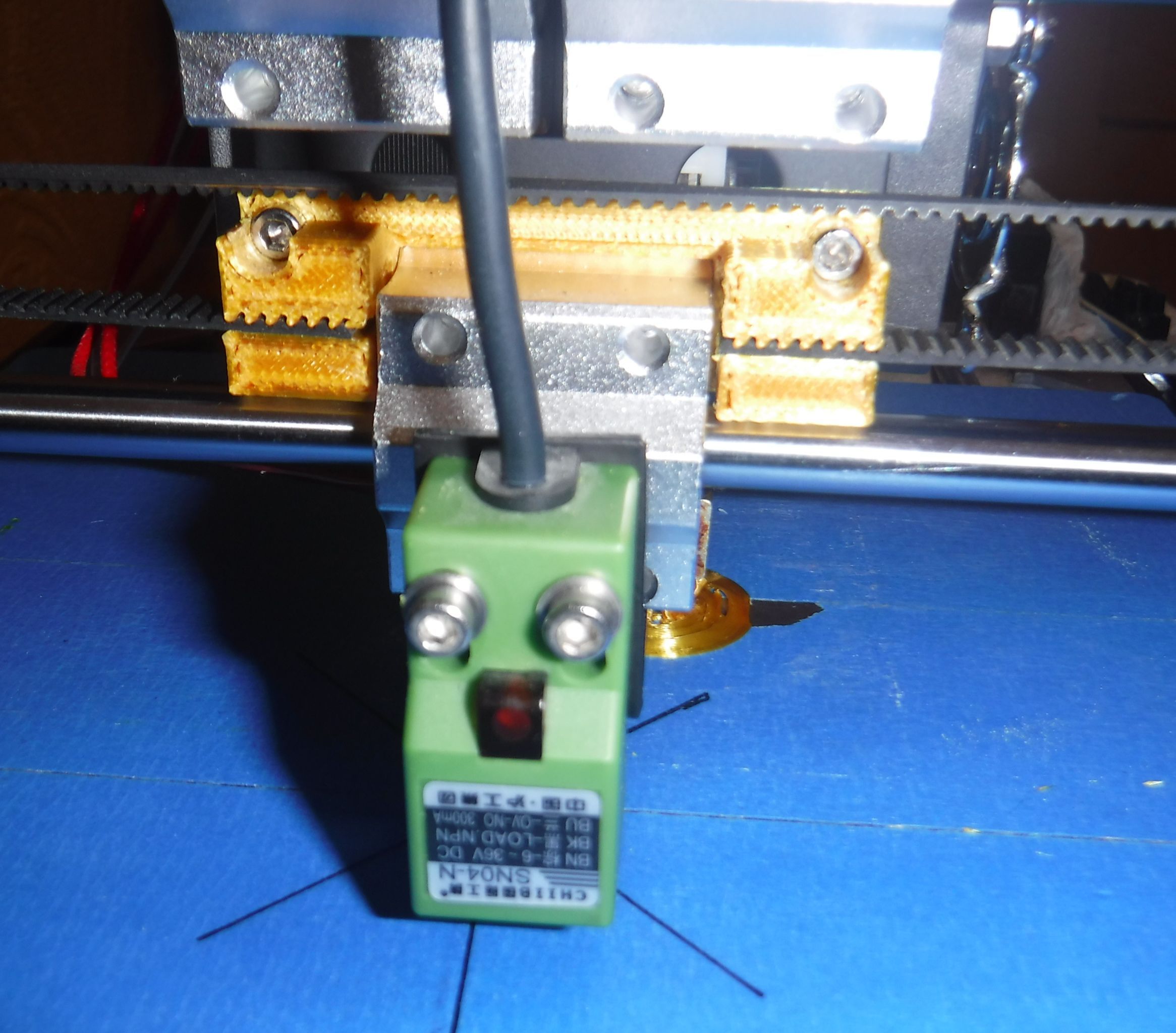
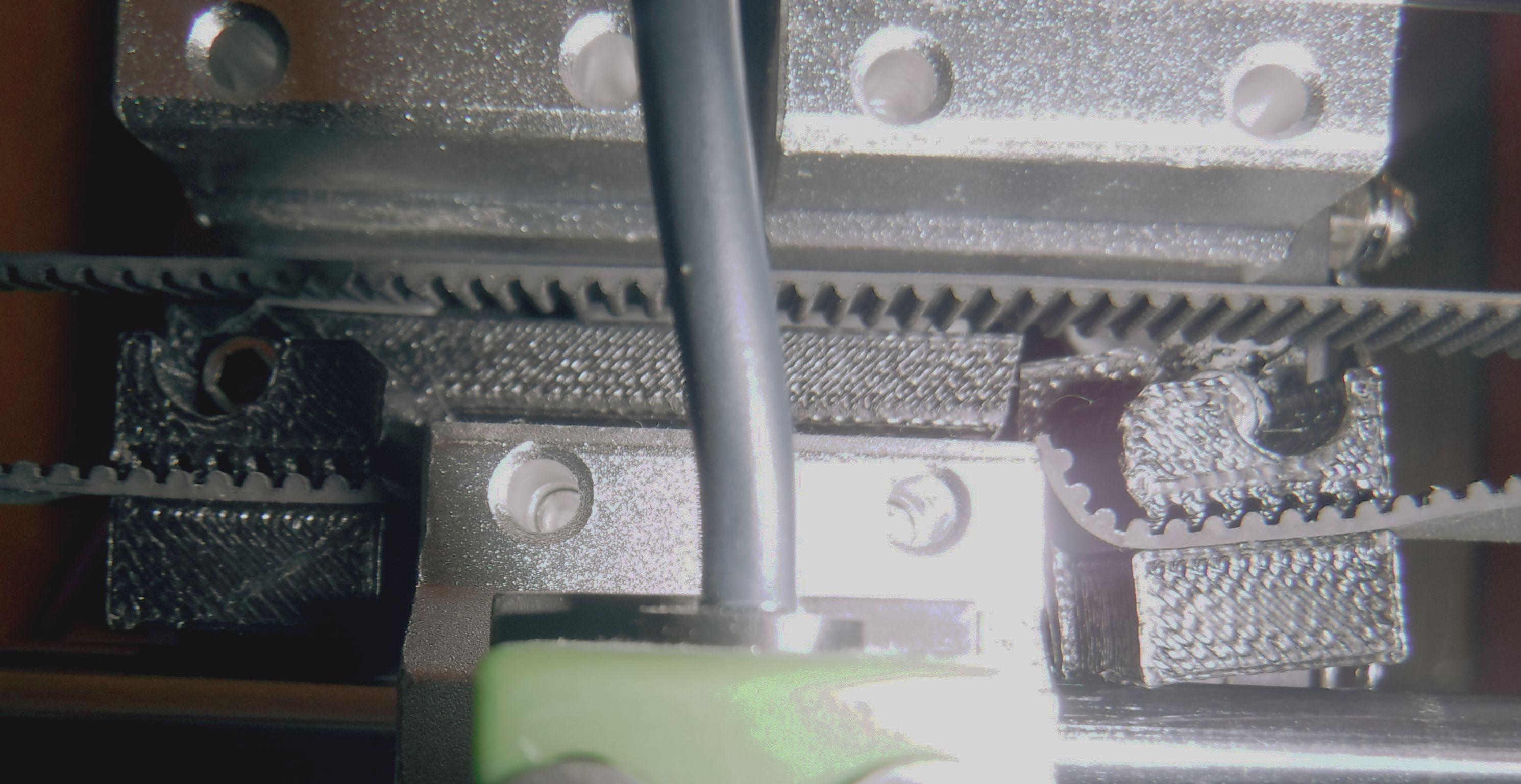
During the process of a 3d print run, I noticed that the object being printed had started to develop a vertical lean.
Upon further investigation I found that the X Axis belt was slack.
As to the cause this turned out to be a broken clamp, that although still attached had cracked at both bolt holes and separated into two separate pieces.
At this point it seemed obvious to go to the manufacturers web site and purchase another one.
However, this proved fruitless due to the age of the printer, not very old but as technology moves on at a pace, quickly making equipment obsolete.
Further searches did reveal alternative sources but by this point it occurred to me that I could print a replacement. But in order to print a replacement I would need a 3d file.
Searches revealed that these were available, but looking at the part in detail it did not seem too complex a task to create this myself.
As the original part was a 3D print it seemed appropriate to replace it like for like.
The original part was black the replacement is in orange 3d printed and fitted as the replacement.
I already knew which application would be used to create the object file, BlocksCAD.
But first I had to take the measurements of the original part.
Measurements taken I then had to input these into BlocksCAD to create the 3d object.
However, BlocksCAD is somewhat different to other CAD packages in that objects are created programmatically rather than the user drawing objects.
These are the steps required to create the X Axis Clamp object.
Downloads
Open the Editor
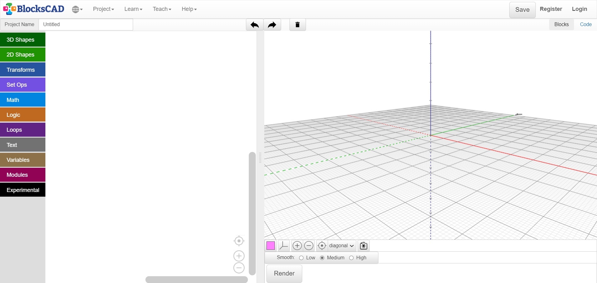
Open the BlocksCAD Editor.
In the Project Name field enter the filename, X_Axis_Clamp
As you progress with the development, I would save the file at regular intervals as a precaution against loss, but this should be standard practice when working in any application.
The easiest way to create the object is by breaking it down in to the basic shapes available.
This means making use of cube and cylinder.
The majority of the elements can be realised with cube (main body and castellation), and cylinder (bolt holes).
Creating the Left Clamp Block.
Because of the shape of the clamp I subdivided it in 3 section, two clamp blocks and an interconnecting arm.
Each clamp was than subdivided into smaller sub blocks.
There are two clamp blocks and the left block will be created first.
The main features of the clamp block are that it is made up of a number of rectangular and cylindrical elements.
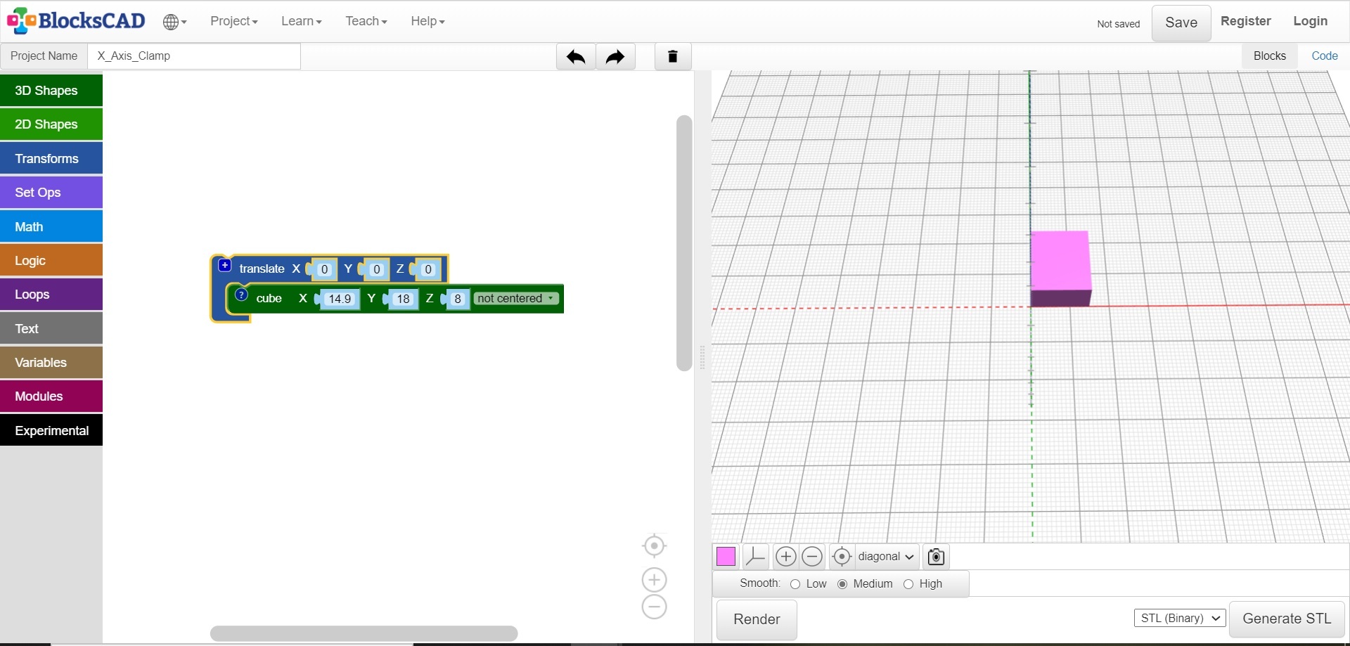
The first of these rectangular element’s measures (x, y, z) 14.9 x 18 x 8 mm* and is created using cube from the 3d shape menu.
*All dimensions are in mm.
Its position in space is controlled using translate from the Transform menu. (x, y, z), 0, 0, 0, this is the centre of the drawing area.
Screw Holes
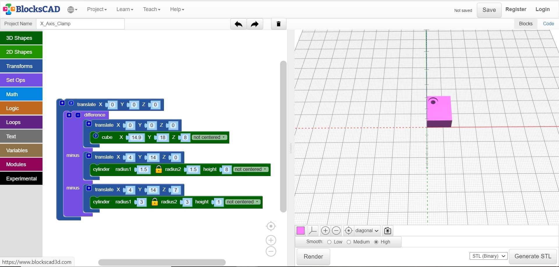
Within this rectangle will be placed a screw hole and recess for the screw head,
The screw hole centre is placed using the translate element 4, 14, 0 and created using cylinder from the 3d shape menu with radius 1.5 and Z = 8.
The screw head hole is placed at 4,14,7 with cylinder dimensions radius 3, Z = 1.
However, just applying these commands would only create the rectangle, in order to create the holes for the screw another command has to be employed, this being difference. Found on the Set Ops menu.
This has the effect of subtracting one shape from another.
In summary this draws a rectangle and two cylinders at the specified co-ordinates and because the difference object is used subtracts the cylinders from the rectangle leaving a hole for the screw and head. Because, the cylinder extends up from the X co-ordinate the screw hole starts at the base of the rectangle and the screw head starts 7mm up from the base therefore Z = 0 and Z = 7 respectively.
In addition to applying co-ordinates to individual elements which allows each object to be specifically placed. It may then be required to position all the elements retaining the relative positions to each other at a different starting point.
This is achieved by enclosing all the objects with a translate command.
You may notice the inclusion of a variable 'b' which allows dynamic positioning within code or from passing parameters into a module. The value at this stage is zero. The purpose of this variable will become clear later.
At any time, the outcome of the commands can be checked with the Render button (lower left of the drawing area). Three options for Smoothing are available Low, Medium and High, with object quality improving from with each option but higher quality comes with a time penalty.
Therefore, whilst working on a new design it’s worthwhile setting Smoothing to Low and using High for the finished object.
Adding the Teeth
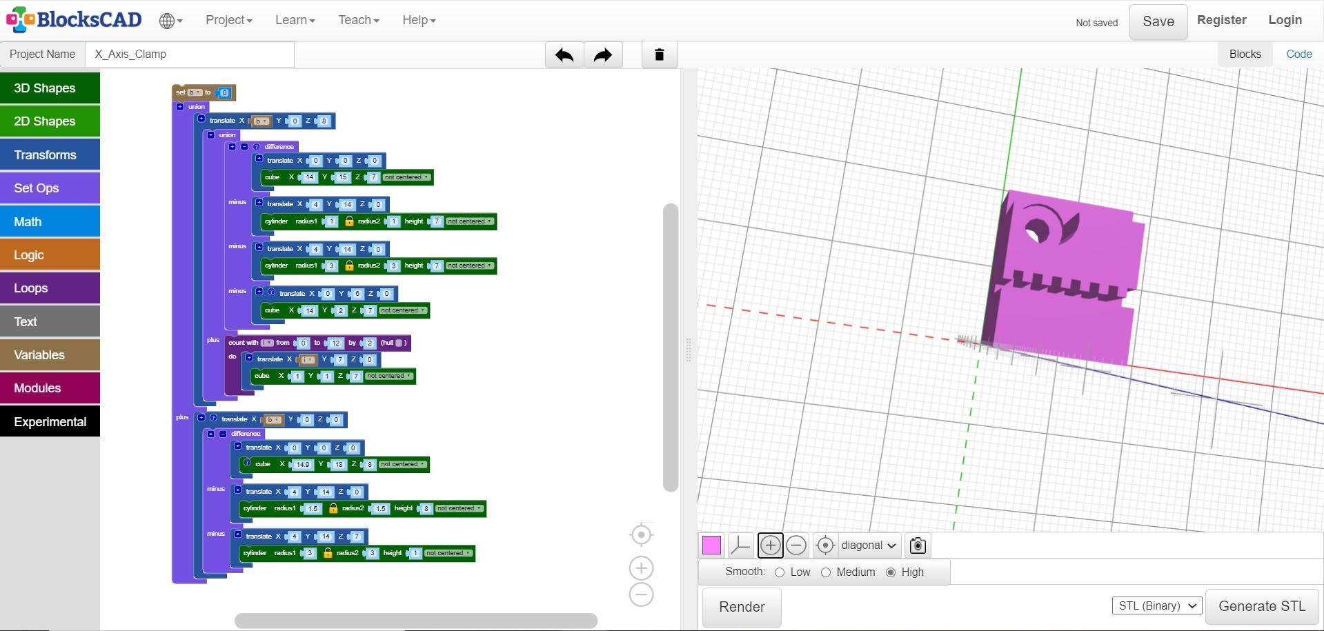
A slightly smaller rectangle with aligned screw holes sits on top of this one again using the format previously described. But with the added teeth to engage and hold the drive belt in place whilst retaining tension.
Taking the previous objects and changing the values as required we have created a smaller rectangle (14 x 15 x 7), and placed a screw hole at (4, 14, 0), radius = 1 and height = 7, then a hole for the screw head at (14, 14, 0), to align with the screw hole with radius = 3 and height = 7.
Into this rectangle we place a slot at (0, 6, 0) with dimensions 14 x 2 x 7 to accommodate the teeth.
This is all bound with the difference commend which subtracts the 3 minus elements from the rectangle.
At this stage we then need to add the teeth.
For simplicity this will be created using the loop object.
We specify a start and end for the count and how many steps and assign this to a variable.
So, in this case the variable ‘I’ will start at 0 and increment by 2 to 12 creating 7 steps.
The variable is applied to the x axis of the translate object connected to the cube object and draws a 1 x 1 x 7 rectangle on the top edge of the slot at incremental positions from (0,7,0) to (12,7,0)
These elements are grouped together using the Union object and the translate object allows the whole group to be positioned at any co-ordinate.
All these elements are brought together to create the left clamp and the variable ‘b’ allows its x co-ordinate to be changed to any position required.
Creating the Right Clamp Block
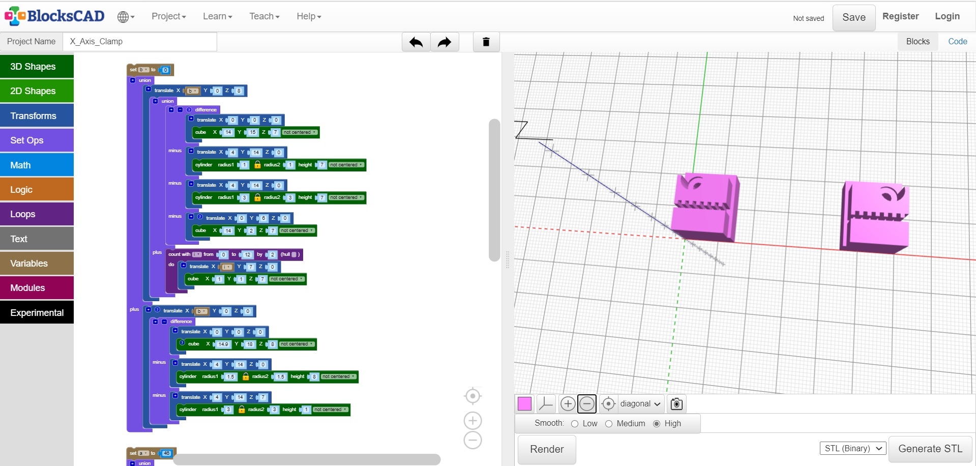
All the work has been done creating the left clamp, which means that the task of creating the right clamp is much simpler.
Copy all the objects and change the value of the variable 'a' which places a copy of the clamp at X = 46.
Then change the translate x values for the screw and screw holes to move these to the right.
Adding the Connecting Arm
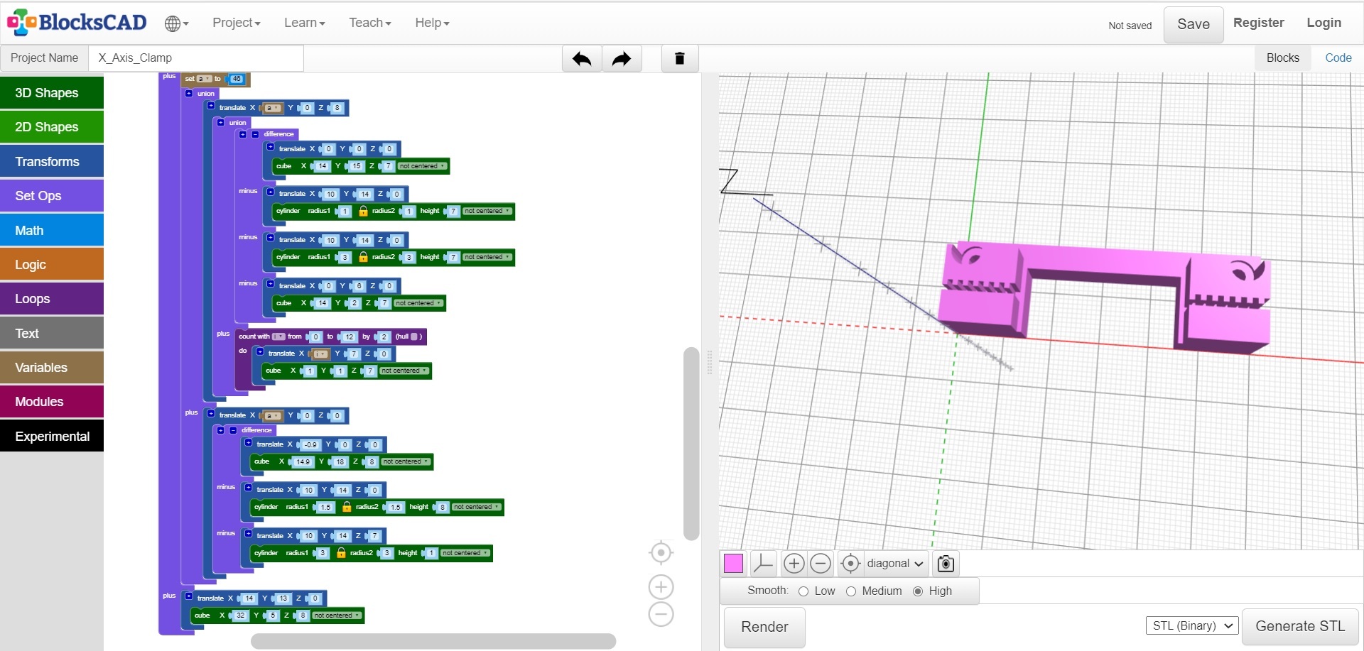
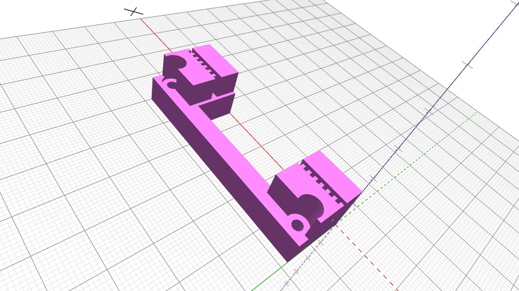
The bar that connects them all together is the last element.
Placed at (14,13,0) with dimensions of 32 x 5 x 8
This completes the object code for the X-Axis clamp block.
Finally
Save the Blocks code this will be an XML file.
The option to save it in OpenSCAD is available as an SCAD file.
An image of the rendered drawing can be saved as a JPG file.
The object file for the rendered object can be output in a number of formats.
Be sure to Render the object using Smoothing High prior to generating the file for maximum quality.
I used OBJ for use with the slicer in this case Cura to create the 3d printer file.
The OBJ files and 3D printer details can be found at Pinshape