HEXlight Made From Scratch


Hey Guys what's up!
HEX LIGHT is a small, hexagon-shaped RGB light that is created using custom PCBs and a 3D-printed body. An Attiny85 MCU controls 48 WS2812 2020 Package Mini Addressable LEDs in this system.
The idea behind this project was to create a modern RGB light that I could add to my display for aesthetic purposes. It adds to the overall appearance of the desk.
Inside the PLA-based 3D-printed body, six PCBs are housed and joined in the form of a hexagon.
Additionally, a diffuser made of transparent PLA spreads the leds light so that the entire hex light section glows.
I made a simple mount that is attached to the TV with a screw so that I could put this hexlight on top of a 32-inch LED TV.
This Instructables is about the whole built process, so let's get started.
Supplies
Following are the materials used in this built-
- Custom PCBs Provided by PCBWAY
- Attiny85 SOIC8 Package
- WS2812 RGB LEDs 2020 Package
- Diode M7 SMA Package
- Custom 3D Body with transparent lid
3D Design


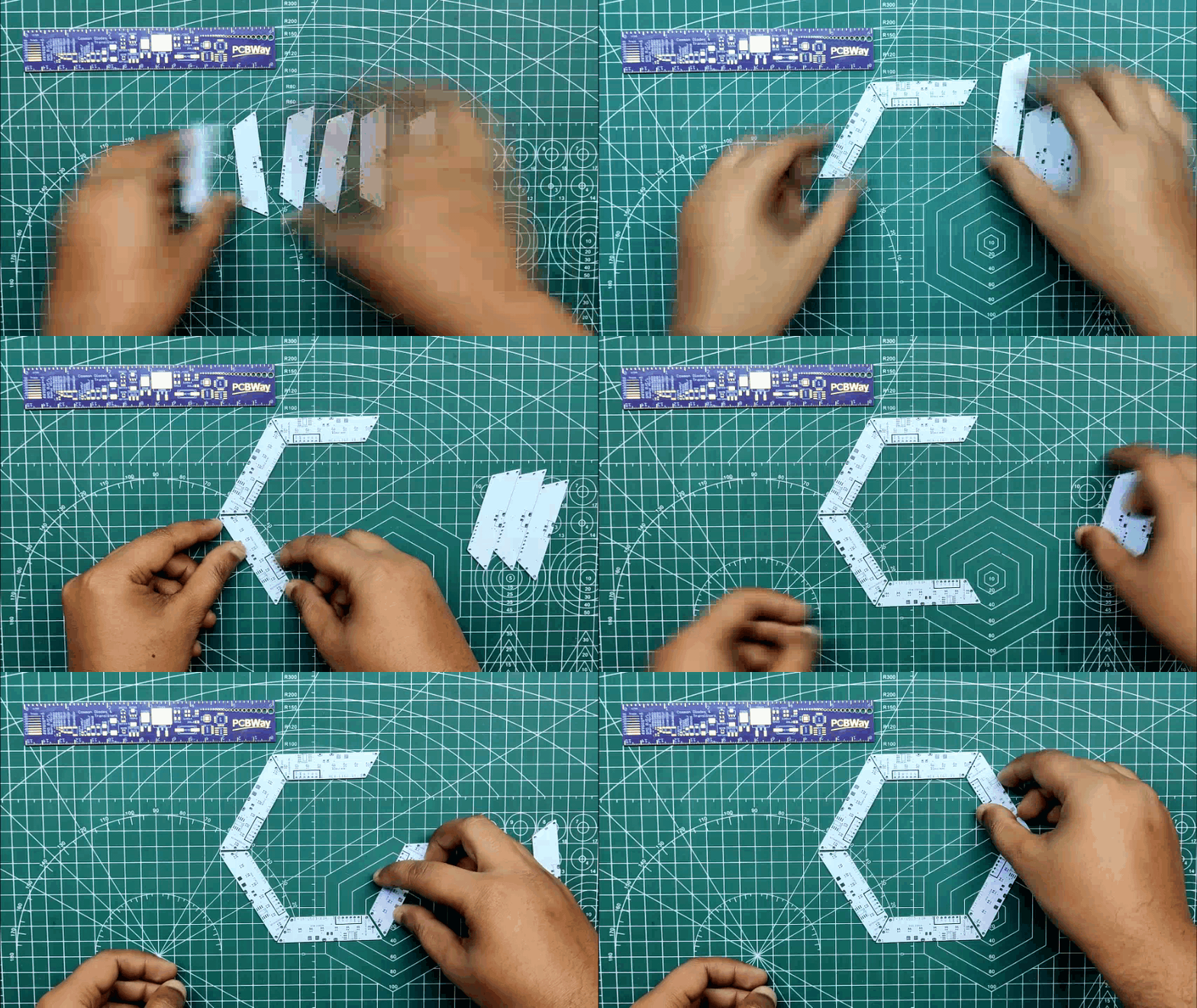
Making the 3D design is the first step in the process. It consists of a single rectangular PCB that has been modeled so that it can be used to create a hexagon; its top and bottom sides have a 120-degree angle. A total of 6 PCBs were used to create the hexagon, and each PCB is connected to the next by its top and bottom sides.
A slightly larger body with a top that serves as a diffuser houses the hexagonal PCB setup.
I added two circular sections to the interior of the hex shape that will be used to mount this body to anything.
I also modeled a TV mount, which will be mounted on the back side of the hex body through the circular section with an M3 screw.
After finishing the design, I exported all of the 3D parts and printed the base in orange PLA with a 0.2mm layer height and 0.4mm nozzle. The lid and TV mount were both built using the same settings.
PCB Design


First, we create a design that consists of an Attiny85 connected to eight WS2812 LEDs, with power coming from a USB mini connector. In the 3D design, the PCB shape has already been defined.
The best choice here was to utilize the Attiny85, a little AVR MCU fairly capable of substituting a conventional Arduino for basic projects. As for using the Attiny85 in this project, this PCB is small, and it's just 16 mm wide, which isn't too much space for placing full development boards or even ESP boards.
I've used it in many of my projects, and using the Attiny85—which is essentially an Arduino shrunk into a small SOIC8 or DIP8 package—is incredibly simple and user-friendly.
On the top and bottom sides of this board, three CON1 ports that are wired to the 5V, GND, and Din-Dout ports are present. Din is attached to the top side, while Dout is connected to the bottom pin.
After the schematic is complete, the PCB design follows. I created an outline based on the dimensions and shape of the HEXLAMP PCB and placed 8 leds in a row, from top to bottom.
PCBWAY

.gif)
.gif)
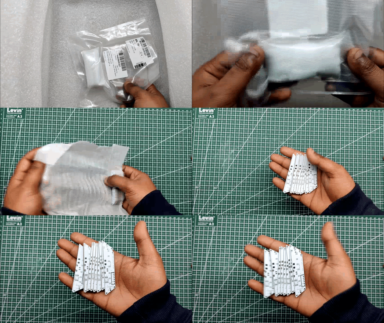
After I completed the PCB, I generated the Gerber data, which was then sent to PCBWAY for samples. An order was placed for the PCBs with white soldermask and black silkscreen as its look pretty cool in general.
I received PCBs within a week, and they were excellent, as expected.
I love the quality of PCBs made by PCBWAY. There are other manufacturers available, but their service is always on another level.
check out PCBWay service for getting great PCB service at less cost.
PCB Assembly
.gif)


- The first step is to apply solder paste to each component pad.
- We then used an ESD tweezer to carefully pick and place all the SMD components in their assigned places one by one.
- Next, we carefully lifted the whole circuit board and place it on my DIY Mini Hotplate which is also homemade just like this project.
After a little time, when the hotplate reaches the temperature where the solder paste is melting, all of the components will be soldered using this hot reflow process.
Programming the Attiny85 With Arduino ISP


An ISP Programmer like USBASP can be used to flash the Attiny85A, an AVR MCU, or we can build a basic ISP Programmer using an Arduino Uno or Nano board.
- We go to Example sketches> Arduino as ISP and upload it into the Arduino Nano board.
- Next, we add a 1uf Capacitor between RST and GND Pin, this will stop Arduino to reset during the flashing process (Add capacitor after uploading the Arduino as ISP Sketch)
- Now go to this link and download the Attiny85 Core files-
https://github.com/SpenceKonde/ATTinyCore
- Next, we wire Attiny85A's SPI Pins with Arduino Pins according to the attached wiring diagram.
- we then go to tools and change the MCU and choose Attiny85.
- We select the right port and change the programmer to "Arduino as ISP"
- Next, we click on Burn Bootloader, if the wiring is correct, you will see a "Done burning Bootloader" message.
- At Last, we go to the sketch menu and select "upload using programmer" and the board will get flashed with the sketch which was opened at that moment.
For flashing the MCU, I used my existing AVR Flasher which Is an Arduino Nano that runs Arduino as ISP Sketch.
I created a rudimentary Header pin connection that joins the SPI Pins of the Attiny with the Arduino Nano in order to link the programmer with the Attiny's SPI Pins.
Adding THT USB


After flashing the code, we put the USB Micro Port in its place and soldered it using a soldering Iron, this USB Port will be the main power source for powering the single board with all the other LED boards that are connected in parallel.
CODE


Regarding the code, I'm using the FastLED Library to drive the WS2812 LEDs. In the FastLEDs, there's a sketch called the Pacifica that I particularly enjoy since it starts out by setting the LEDs to one tone of blue before gradually shifting to a lighter tone that resembles an ocean wave.
You can download the library from here- https://fastled.io/
Downloads
Making More RGB Strips
.gif)
.gif)
.gif)
.gif)
.gif)
We have create five other boards that only contain RGB LEDs after setting up the main control board and uploading the code onto it. The main board will be used to operate all of these LEDs.
- On all five boards, we begin by applying solder paste one by one to each LED pad. Then we pick and place all the RGB LEDs in their place
- Finally, we heat the solderpaste until it melts and all of the LEDs are soldered into their respective positions on each board using a Mini Hotplate.
Testing Each Strip
.gif)

Next, because the WS2812 2020 Package is so tiny, we test each board to verify if the LEDs have been soldered properly or not. This is necessary to determine whether the strip is functional or not.
- Three Male to Male jumper pins are attached to D3, 5V, and GND ports of an Arduino Nano board that is mounted on a breadboard.
- We simply change the pin number and the number of LEDs, which is 8, while keeping the same code.
- We connect the Arduino D3 to the Din of the RGB Board, the 5V jumper pin to the RGB Board's 5V, and GND to GND.
As a consequence of testing every LED board to determine whether the LEDs on each board are functional or not, we may proceed to the next stage, which is connecting every OPCB to create a HEXAGON board.
Main Assembly


We begin by first arranging all of the PCBs into a hexagonal shape. We then connect the main control PCB to the other boards in such a way that the Dout of the main control board gets connected to the Din of the second RGB Board, Dout of the second RGB Board gets connected to the Din of the third RGB Board, Dout of the third is connected to Din of the fourth board, and this goes on and on up to the sixth board.
Silver copper wire is used to connect each board, and each board's 5V and GND are connected in parallel.
RESULT


We then add USB to a 5V source and the setup lit up and we can see that the pacific sketch is working pretty well, it changes from one tone of blue to another and this goes in a loop which looks pretty calming.
Body Assembly


- After that, we use hot glue to permanently attach the hexagon board to the 3D-printed base.
- The lid is then placed on the base body, fitting snugly into place to secure everything.
The assembly of the hexlight is finished.
LED TV Mount
.gif)
.gif)
.gif)
.gif)

- The final step is to attach a TV mount to this hexlight so that we can use this setup with my LED TV. The 3D mount was created from the same transparent PLA as the lid using a 0.4mm nozzle and 0.2mm layer height.
- The TV mount is attached to the Hexlight body with M3 screws.
- We remove one of the LED TV's screws in order to attach the hexlight, and we then screw the mount on top of the removed screw.
- We then tighten the screw, which will keep the mount in place permanently and hold everything together.
Conclusion


The finished version, which is really stunning, features a 3D-printed holder that is placed on top of an LED TV, giving the entire desk a stylish appearance.
Light is neatly diffused by transparent PLA, although there is room for improvement.
In terms of the programming, we can modify the sketch into any other fastLED sketch or create our own.
This project is finished, and you can create your own using the attached files.
Thanks for getting this far; please leave a comment if you need any help with this project.
Special thanks to PCBWAY for supporting this project; do check them out for great PCB service at a lower cost.
Thanks again, and I will be back with a new project soon.