Guide to Modeling a Medicine Themed Cup
by mocha2 in Design > Digital Graphics
95 Views, 0 Favorites, 0 Comments
Guide to Modeling a Medicine Themed Cup
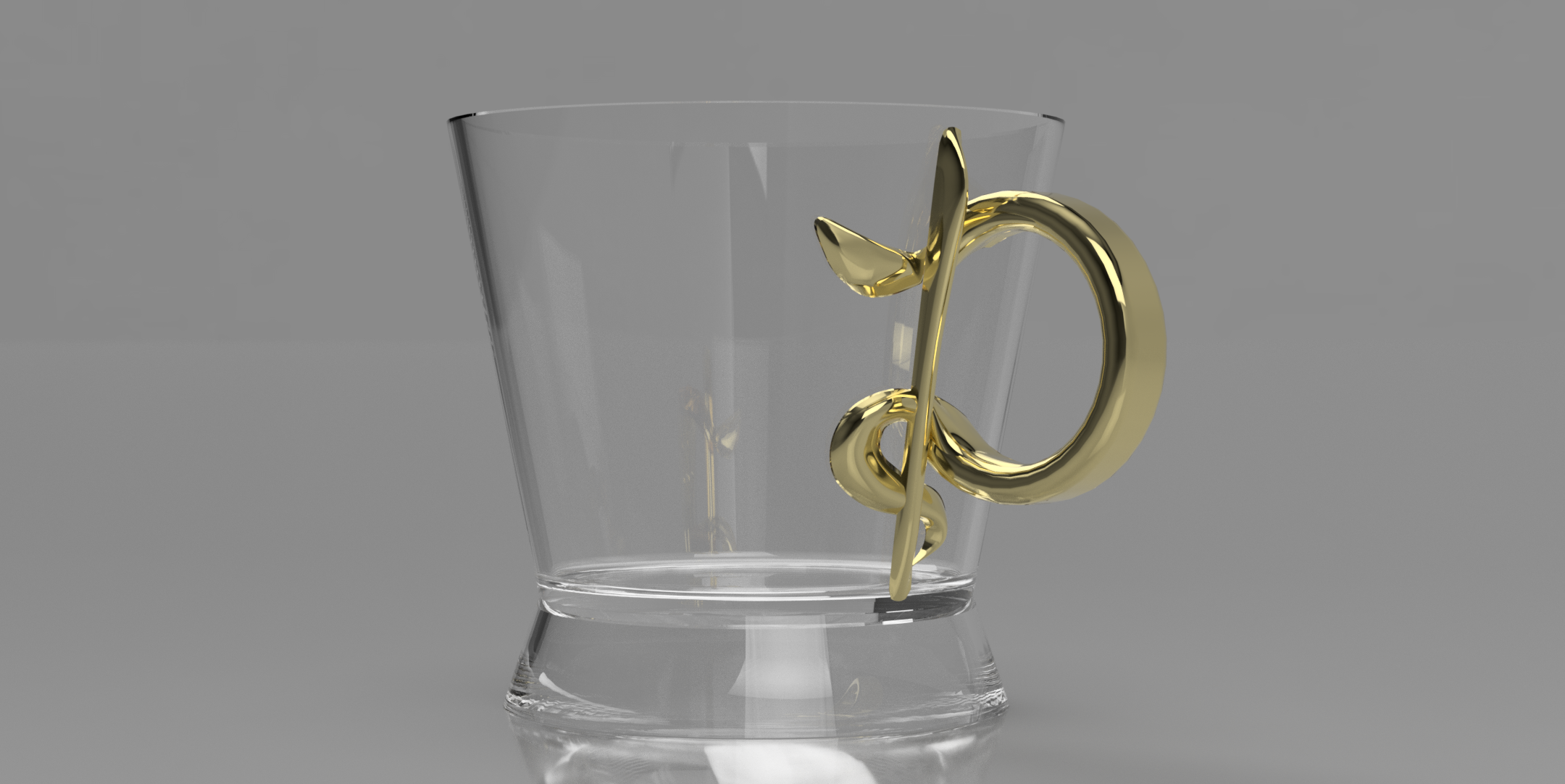
Here is a cup with a handle shaped like a medicine viper on a glass cup. Skills learned: Basic sketches, 3D objects, and how to manipulate forms. The PDF below is another version of all the steps below!
Downloads
Supplies
- Computer
- Mouse
- Fusion 360
BEFORE YOU START: REMEMBER TO OCCASIONALLY SAVE, ESPECIALLY WHEN YOU TAKE BREAKS!
Create a Sketch
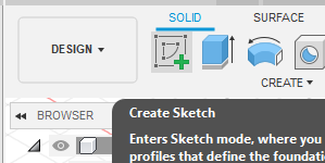
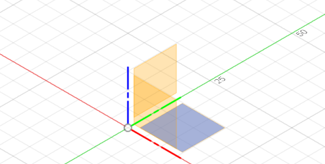
Click “Create Sketch” in the upper-left-hand corner, then select the XY-plane as shown in the right-side picture above.
Select the Circle Tool
.png)
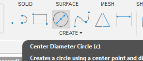
Click on the “Center Diameter Circle” tool in the upper left-hand corner, then click the intersection of the red and green lines when a tag shows up that says “Place center point”.
Make the Circle
.png)
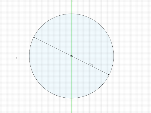
Then drag your mouse outward, and type in 7. This should give you a circle like the one shown above:
Finish Sketch
.png)
Then click “Finish Sketch” in the upper right-hand corner
Rename the Sketch
.png)
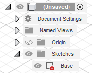
On the left hand side, you can then open the “Sketches” folder and right click on “Sketch1” and rename it to “Base”. After you hit enter, you should have the above:
Making an Offset Plane
.png)
.png)
.png)
.png)
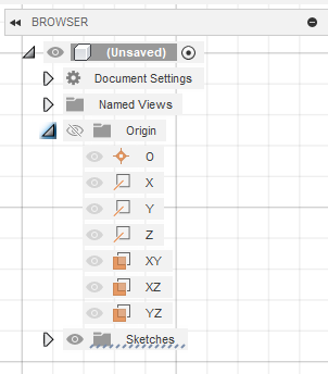
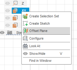
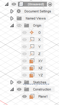
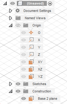
First, open your “Origin” folder on the left-hand side, then right-click the XY plane and select “Offset plane”. Type in 1.5. This should create a new folder named “Construction”. Once you open that, you can right-click on “Plane1” and select “Rename” and rename it to “Base 2 plane”
Make Another Circle
.png)
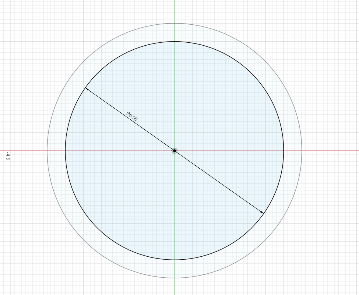
Then click “Create Sketch” again and click on “Base 2 plane”. Just like the previous circle, click on the “Center Diameter Circle” tool in the upper left-hand corner, then click the intersection of the red and green lines when a tag shows up that says “Place center point”. Then drag your mouse outward, and type in 6. This should give you circles like the ones shown above:
Finishing Up the Circle
.png)
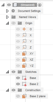
Finally, hit “Finish Sketch” and rename this sketch to “Base 2”
Making Another Offset Plane
.png)
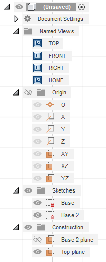
Similar to Step 3, first right-click the XY-plane in the “Origin” folder and click “Offset Plane”. Then immediately enter 8. Then in the “Construction” folder, rename “Plane2” to “Top plane”
Make Another Circle
.png)
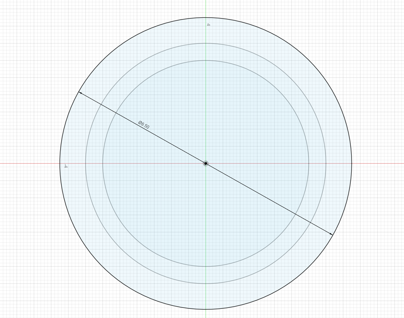
Then click “Create Sketch” again and click on “Top plane”. Just like the previous circles, click on the “Center Diameter Circle” tool in the upper left-hand corner, then click the intersection of the red and green lines when a tag shows up that says “Place center point”. Then drag your mouse outward, and type in 8.5. This should give you circles like the ones shown above:
Finishing Up Another Circle
.png)
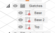
Then, click “Finish Sketch” and rename “Sketch3” to “Top”
Change Perspective
.png)
.png)
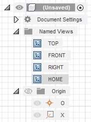
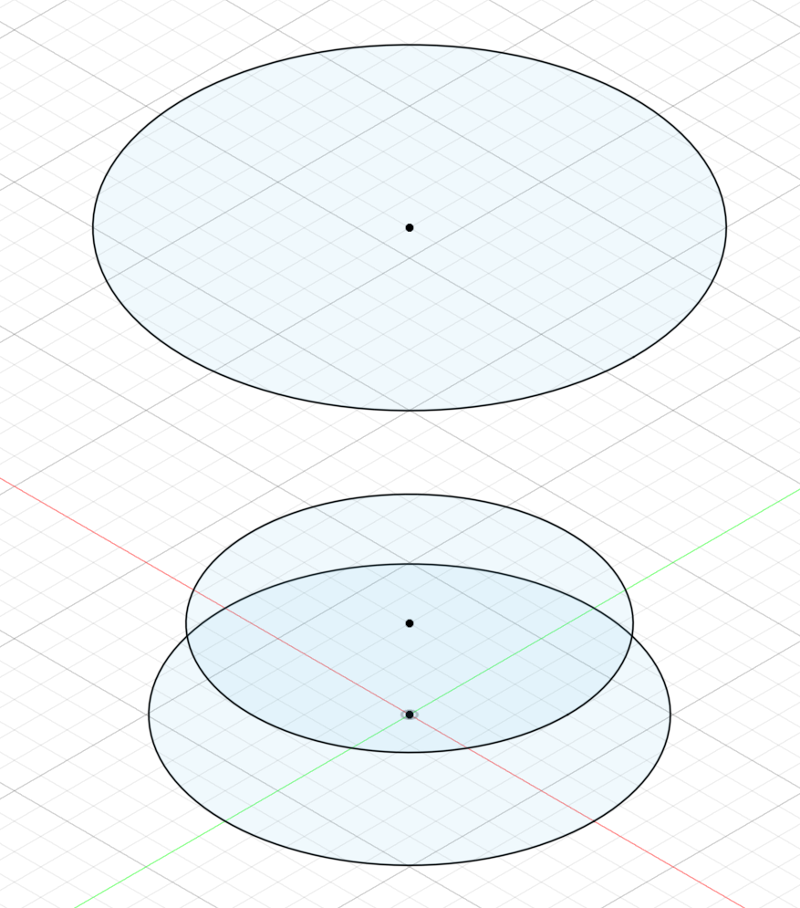
Next, open the “Named Views” folder, and click on home. After you click it, you should see the above.
Loft "Base" and "base 2"
.png)
.png)
.png)
.png)
.png)
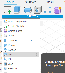
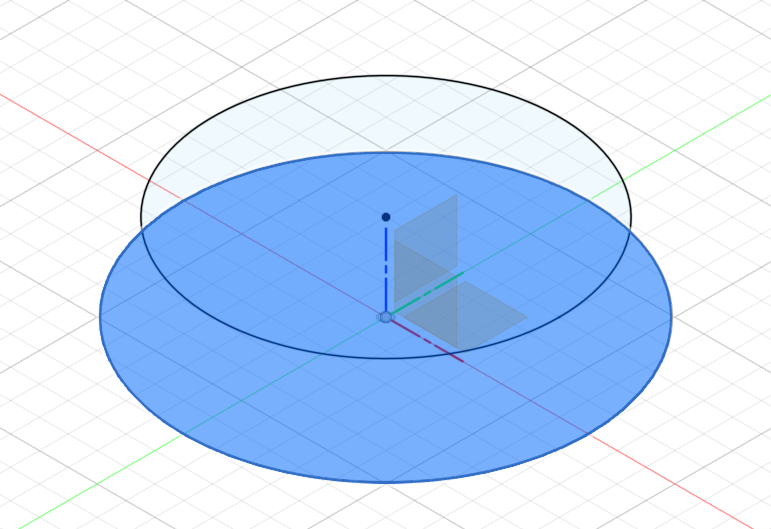
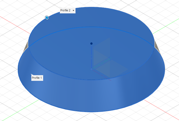
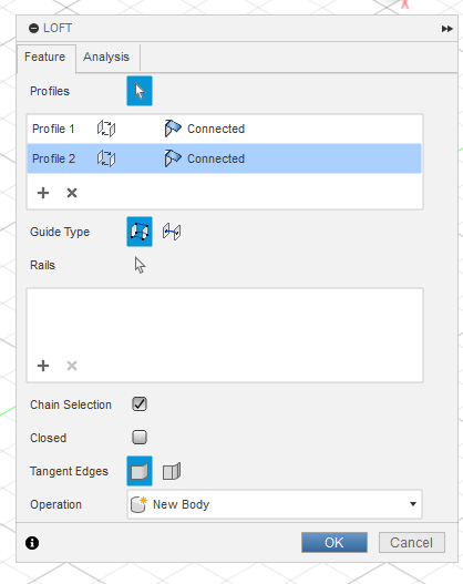
Select the “Loft” tool by first clicking the “Create” dropdown, and then picking “Loft”. First, click on the Base circle (at the very bottom), and then the circle above that (Base 2). Then select “Ok”. Lastly, in the new “Bodies” folder, rename “Body1” to “Base”
Loft "Base 2" and "Top"
.png)
.png)
.png)
.png)
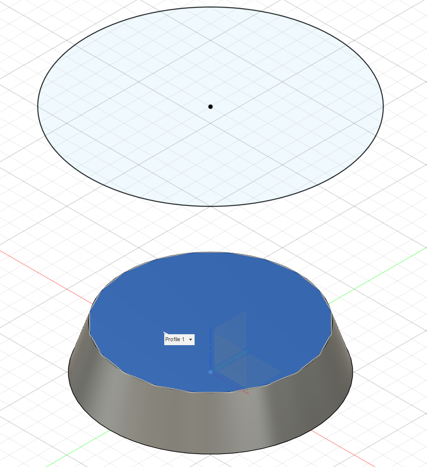
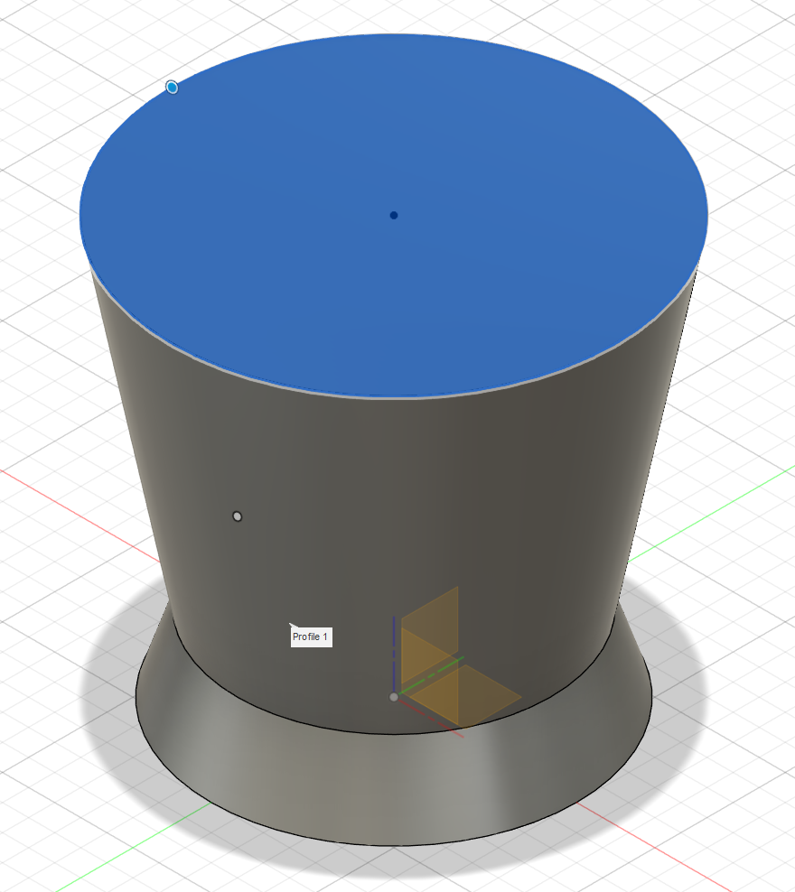
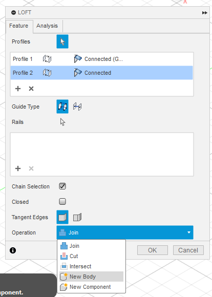
Again, select the “Loft” tool by first clicking the “Create” dropdown, and then picking “Loft”. Then select Base 2 and Top. Before clicking “Ok”, make sure to change the operation to “New Body”, then hit “Ok”. Lastly, rename “Body2” to “Cup”
Hollowing Out Cup
.png)
.png)
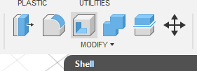
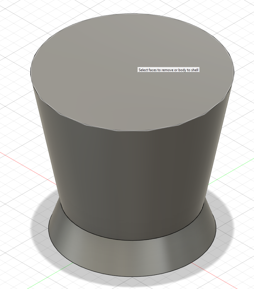
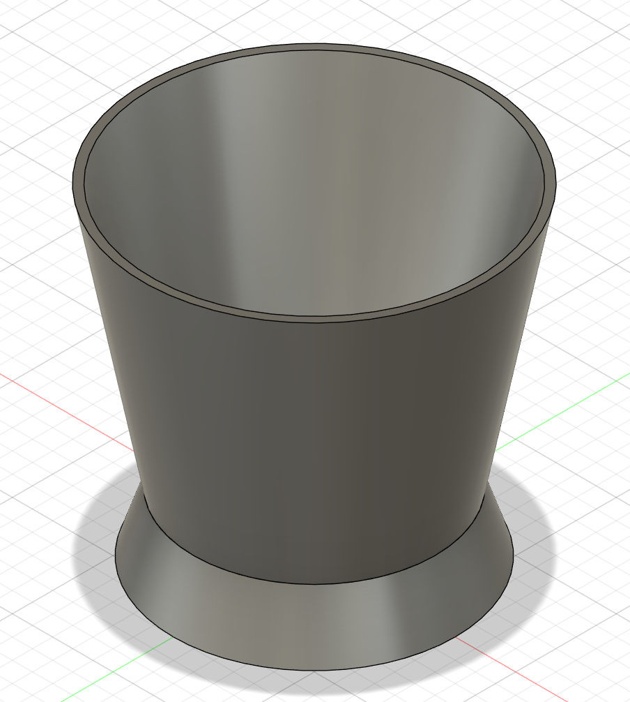
First, select the “Shell” tool. Then select the top circle face. Then immediately enter 0.2 and hit enter. It should now look like the above:
Changing Perspective
.png)
.png)
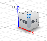
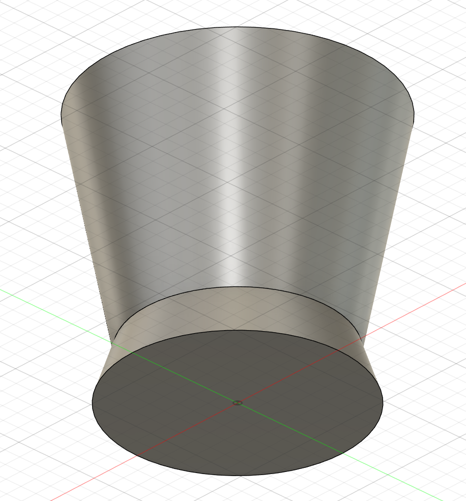
Next, press drag up the corner of the box on the upper right corner of your screen. Drag up until you see the above view:
Hollowing Out Base
.png)
.png)
.png)
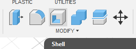
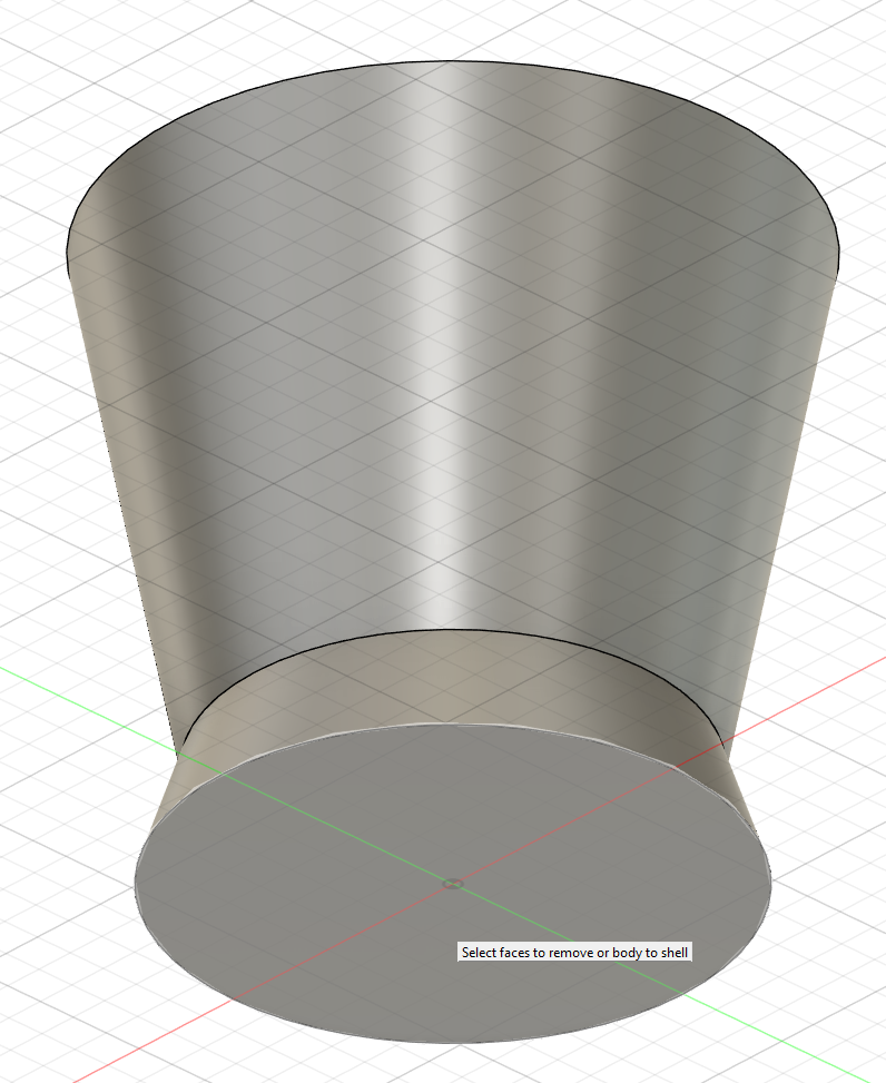
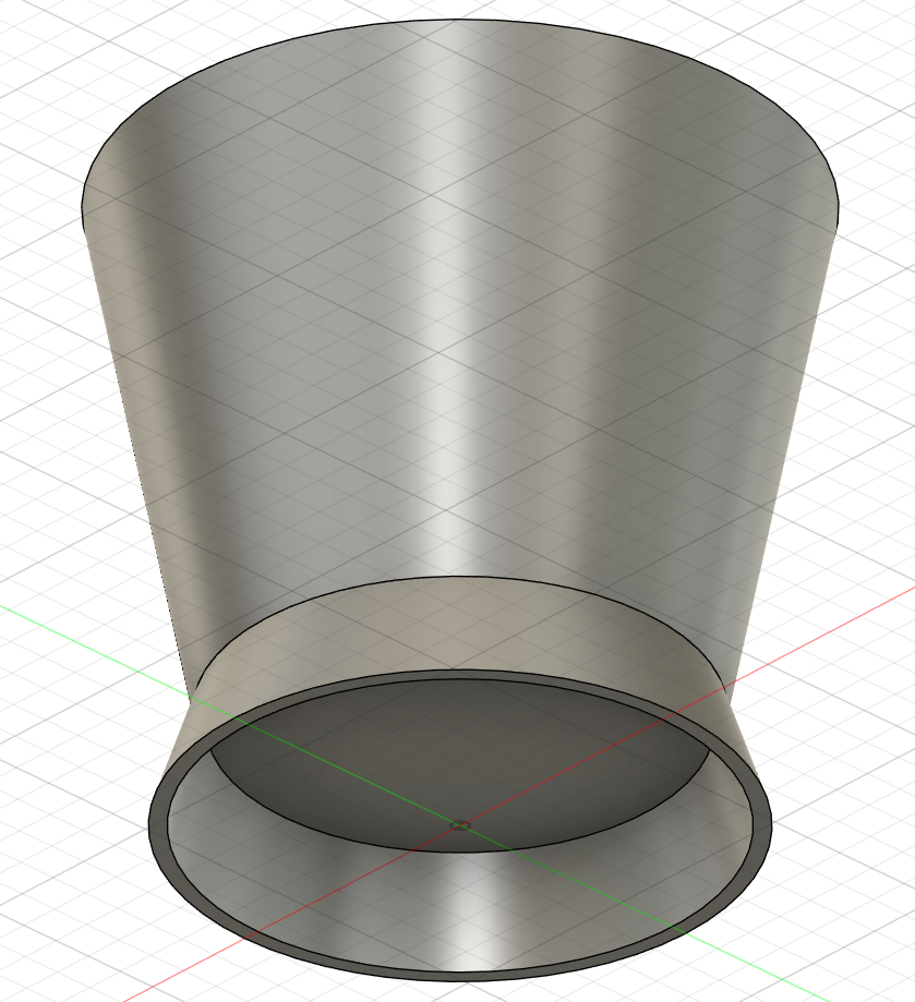
Select “Shell” tool again. Then select the circle face below. Then immediately enter 0.2 and hit enter. It should now look like the above.
Smoothing Out Base Edge
.png)
.png)
.png)
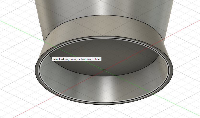
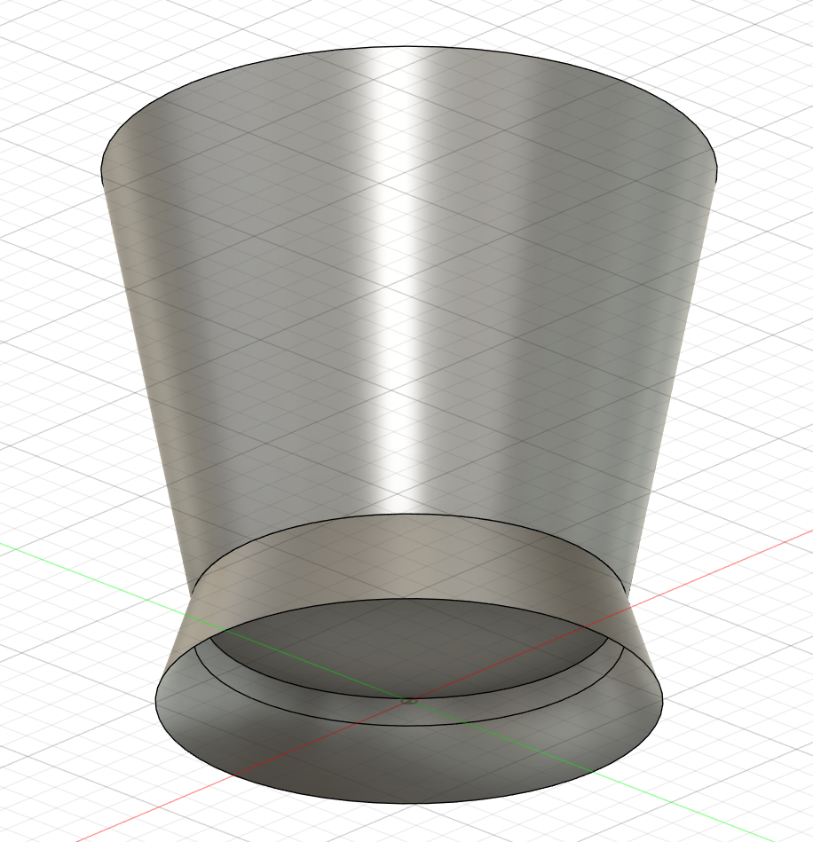
First, select the “Fillet” tool. Then, click on the edge above. Then, immediately enter 2.9. It should then look like this:
Changing Perspective
.png)
.png)
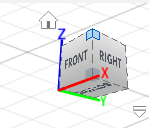
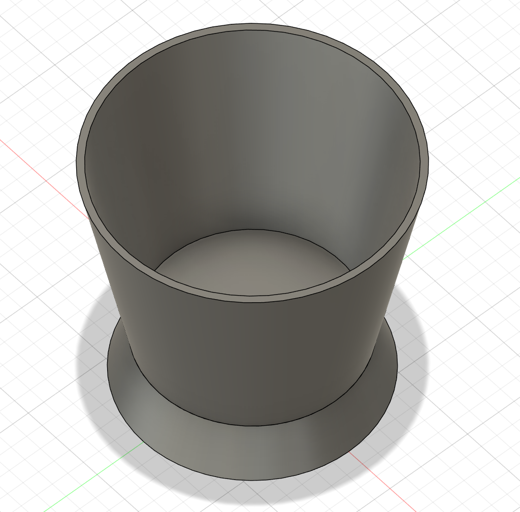
Next, press drag down the corner of the box on the upper right corner of your screen. Keep dragging down until you get the above view:
Smoothing Out Cup Edge
.png)
.png)
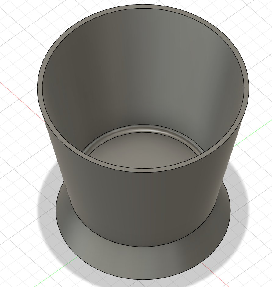
Then, select the “Fillet” tool again. Select the bottom edge. Then immediately enter 0.25 and hit enter. It should now look like the above:
Changing Cup and Base Materials
.png)
.png)
.png)
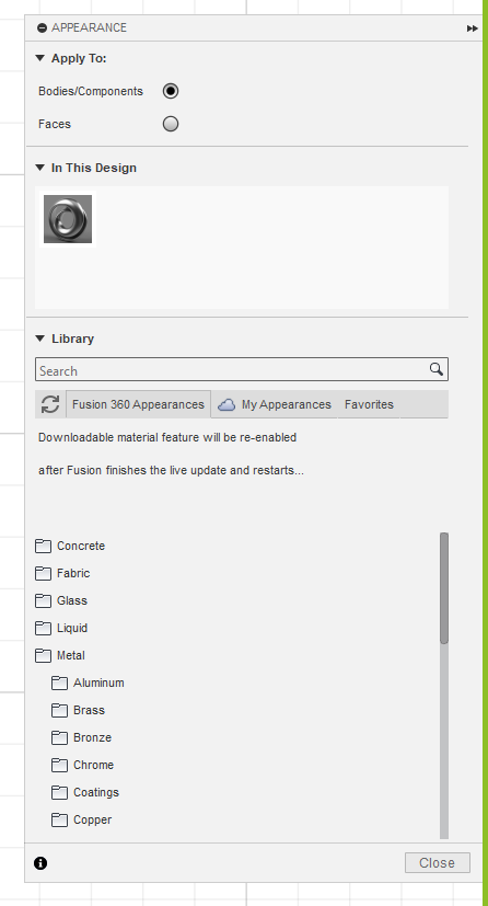
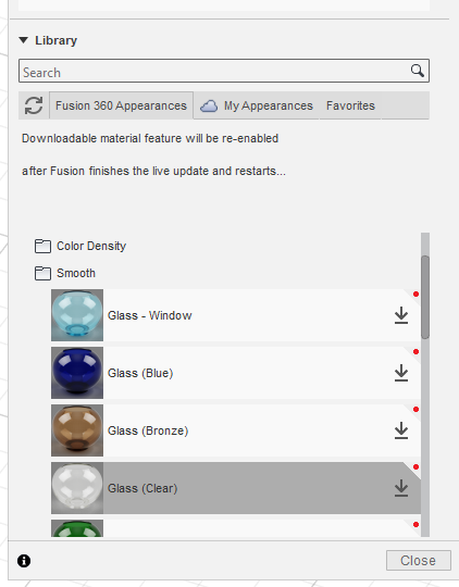
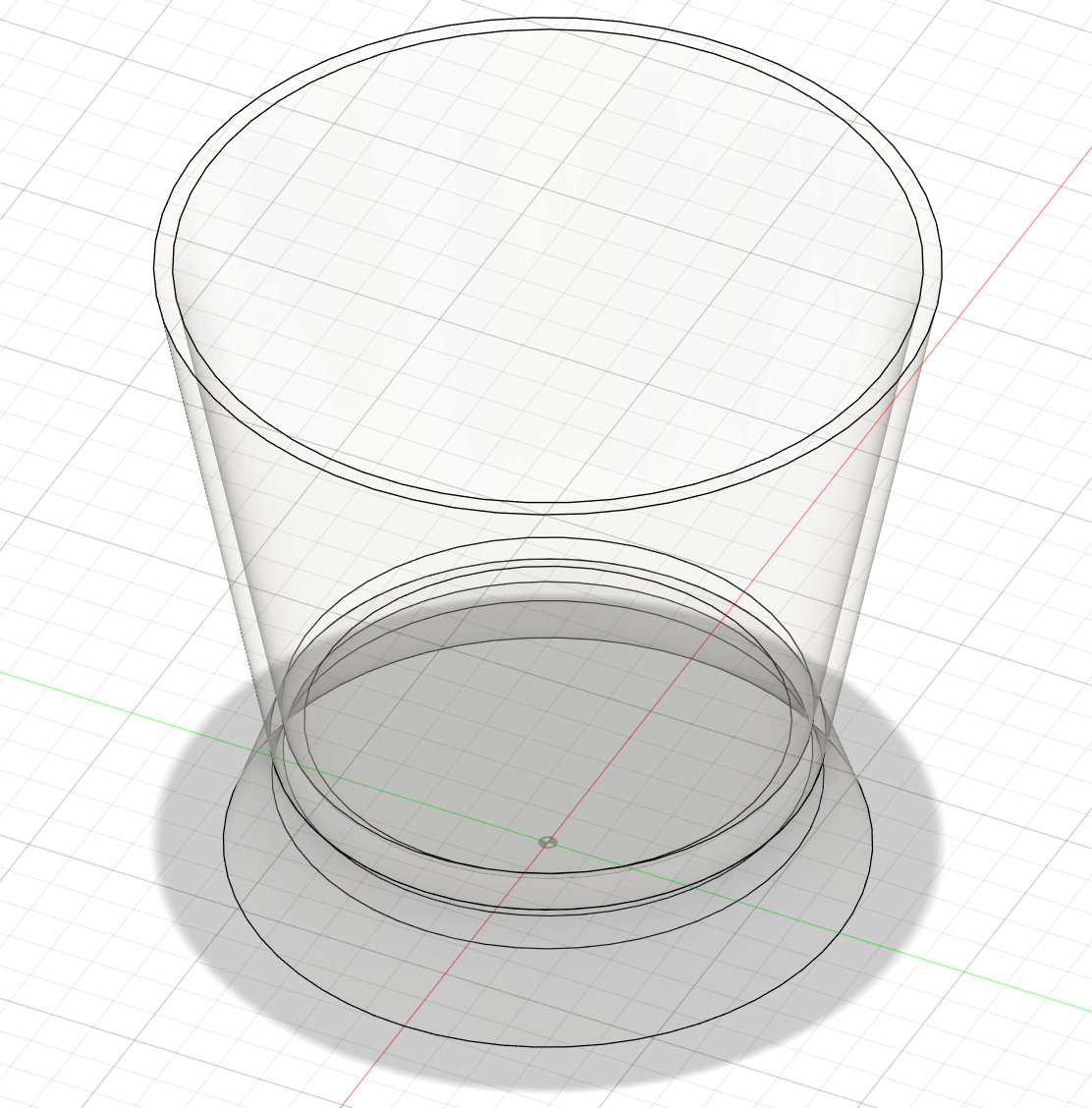
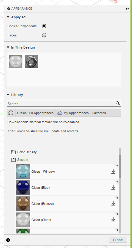
First, type A while on the Fusion360. This menu should show up. Open the “Glass” folder, then open the subfolder “Smooth”. Then, click and drag the “Glass (Clear)” material to the surface of either object, then do the same to the other object. After this, it should look like the picture on the right. Then, click “Close”.
Sketch a Outer Circle for Handle
.png)
.png)
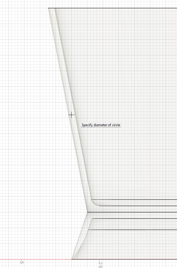
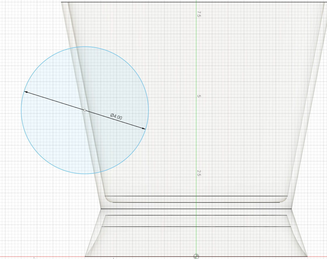
Then, click “Close”. Next, click “Create Sketch”, then select the XZ plane on the left side of the screen. Then select the “Center Diameter Circle” tool again. Next, click about halfway between the Top and Base 2, and in between the two outer lines, somewhere like the first image. Then immediately enter 4, and hit enter.
Sketch a Inner Circle for Handle
.png)
.png)
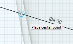
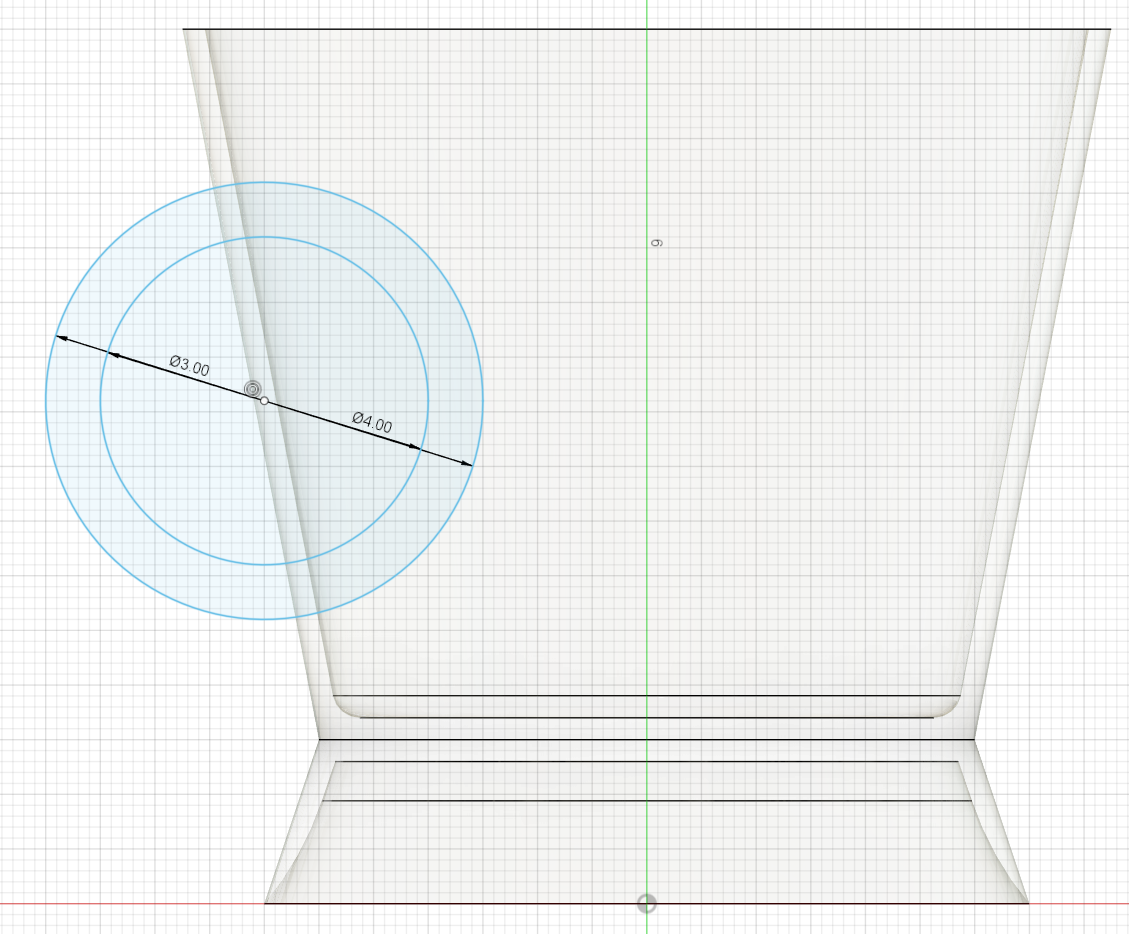
Then select the “Center Diameter Circle” tool again, and this time use the same point as above, this tag shows up. Next, immediately enter 3 and hit enter. It should look like the above:
Move Circles
.png)
.png)
.png)
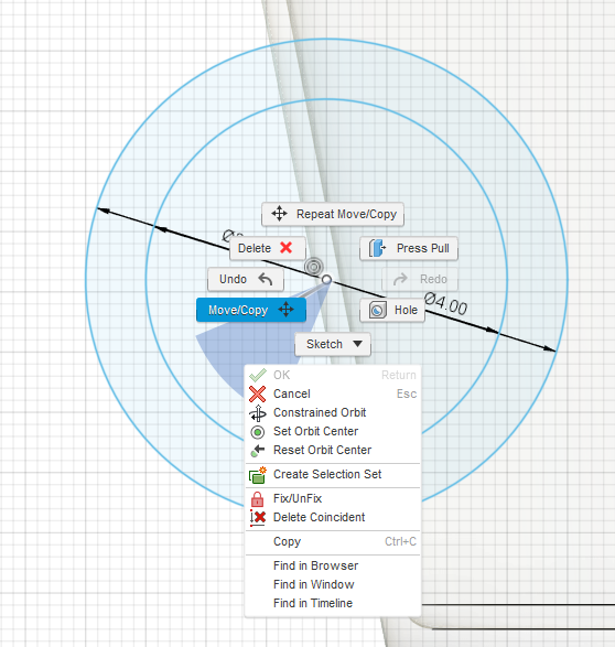
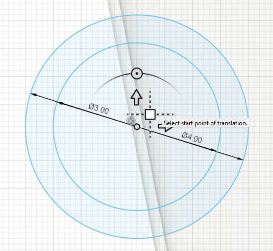
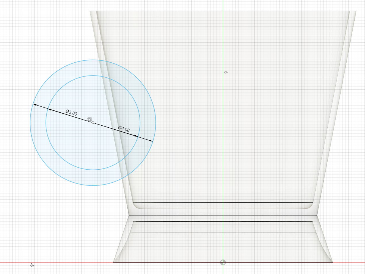
Next, right-click the point and select “Move/Copy”. Then, click and drag the square to move the point until the part of the circle outside of the outermost line looks like a handle. The balance should look like something the above:
Trimming the Circles
.png)
.png)
.png)
.png)
.png)
.png)
.png)

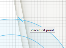
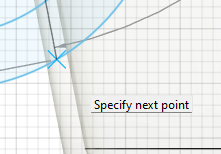
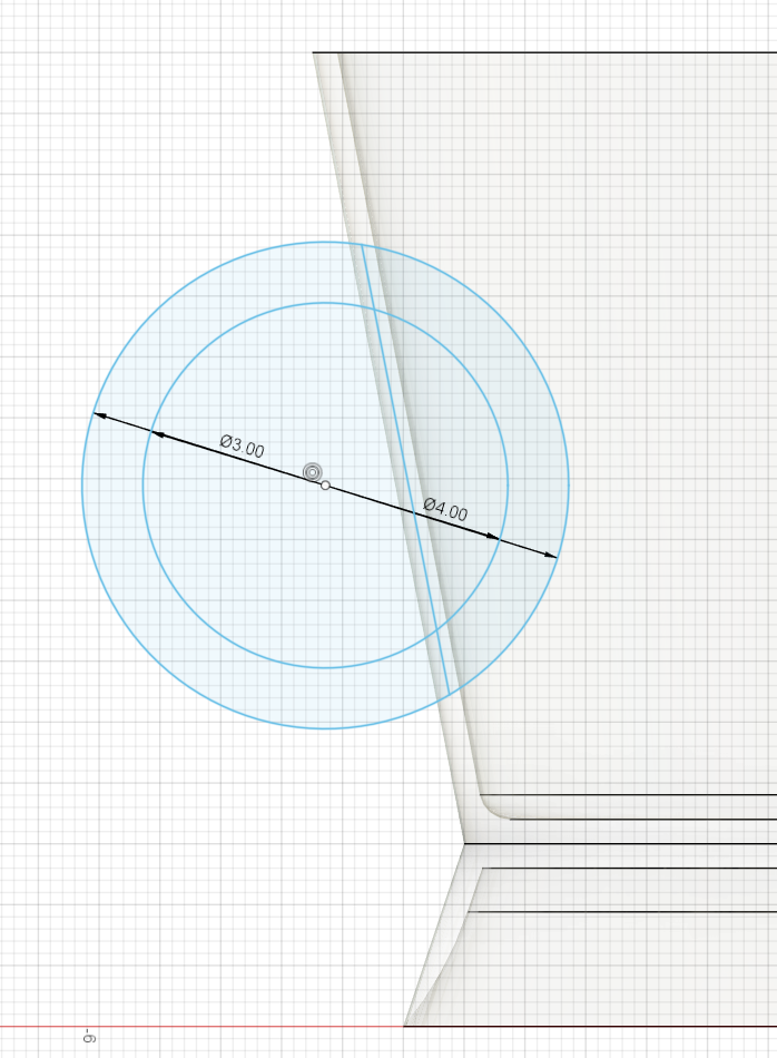
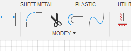
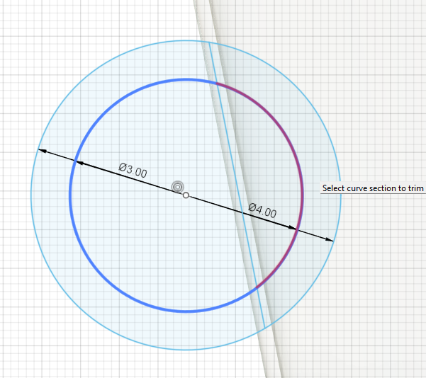
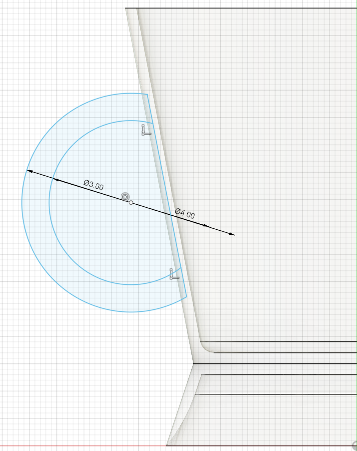
Next, select the “Line” tool. Then, place the first point on the circle in between the two outermost lines. Do the same for the other point. This should be what your sketch looks like. Next, select the “Trim” tool. Then, select the one of arcs inside the cup (it should become red). Do this with the other arc inside the cup. Your sketch should look like the above. Then click “Finish Sketch”. Rename to “Handle”
Make the Handle
.png)
.png)
.png)
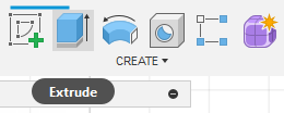
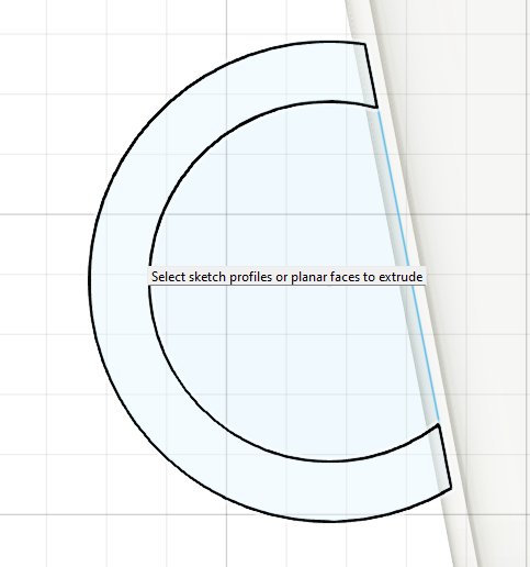
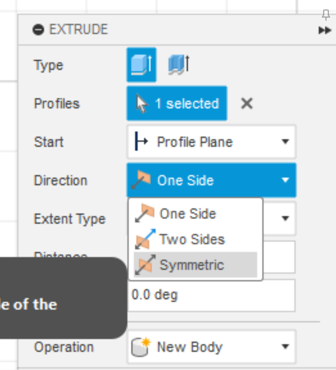
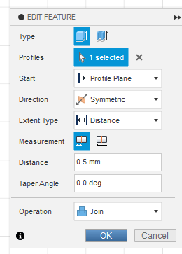
Next, select the extrude tool. Select the outer circle. On the right side of your screen, change the “Direction” to “Symmetric”. For the “Distance” enter “0.5” and change the “Operation” to “Join”, then hit “Ok”.
Smooth Out the Handle
.png)
.png)
.png)
.png)
.png)
.png)
.png)
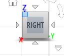
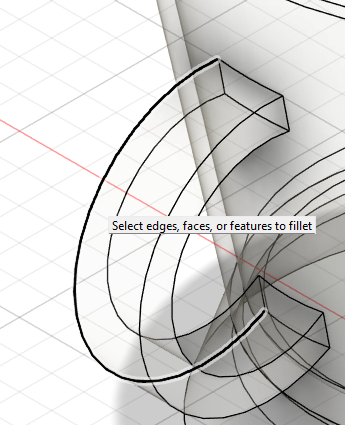
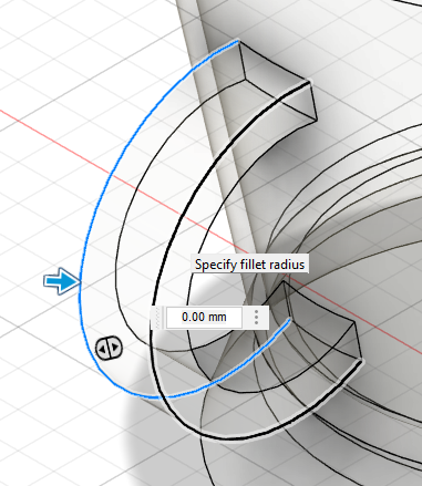
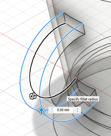
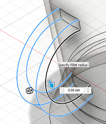
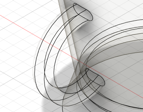
Change your perspective by hitting the upper-left corner. Then select the “Fillet” tool. Select these four edges. Then immediately enter 0.25 and hit enter. It should look like the above.
Change Handle Material
.png)
.png)
.png)
.png)
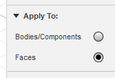
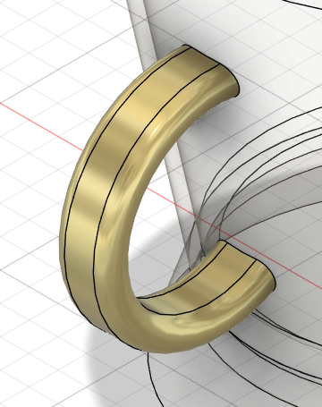
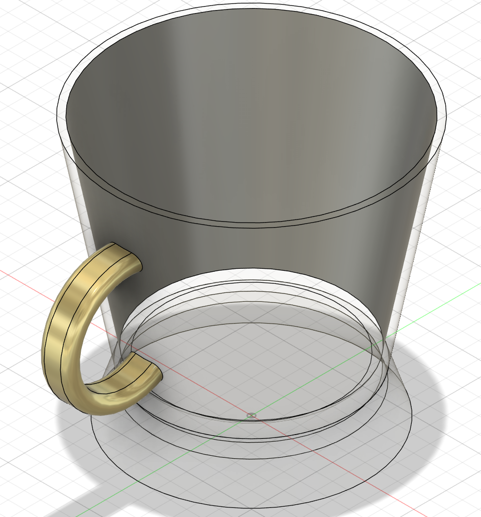
Hit A to bring this menu again. Next, scroll down and open the “Metal” folder, and then the “Gold” subfolder. At the top, change the “Apply to:” choice to “Faces”. Next, click and drag the “Gold - Polished” onto all four of the handle’s faces. End result is above. Lastly, click and drag the “Steel - Satin” onto the inside of the cup (This will be useful for the next step). Should look like the above.
Create First Form
.png)
.png)
.png)
.png)
.png)
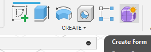
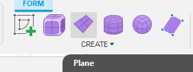
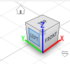
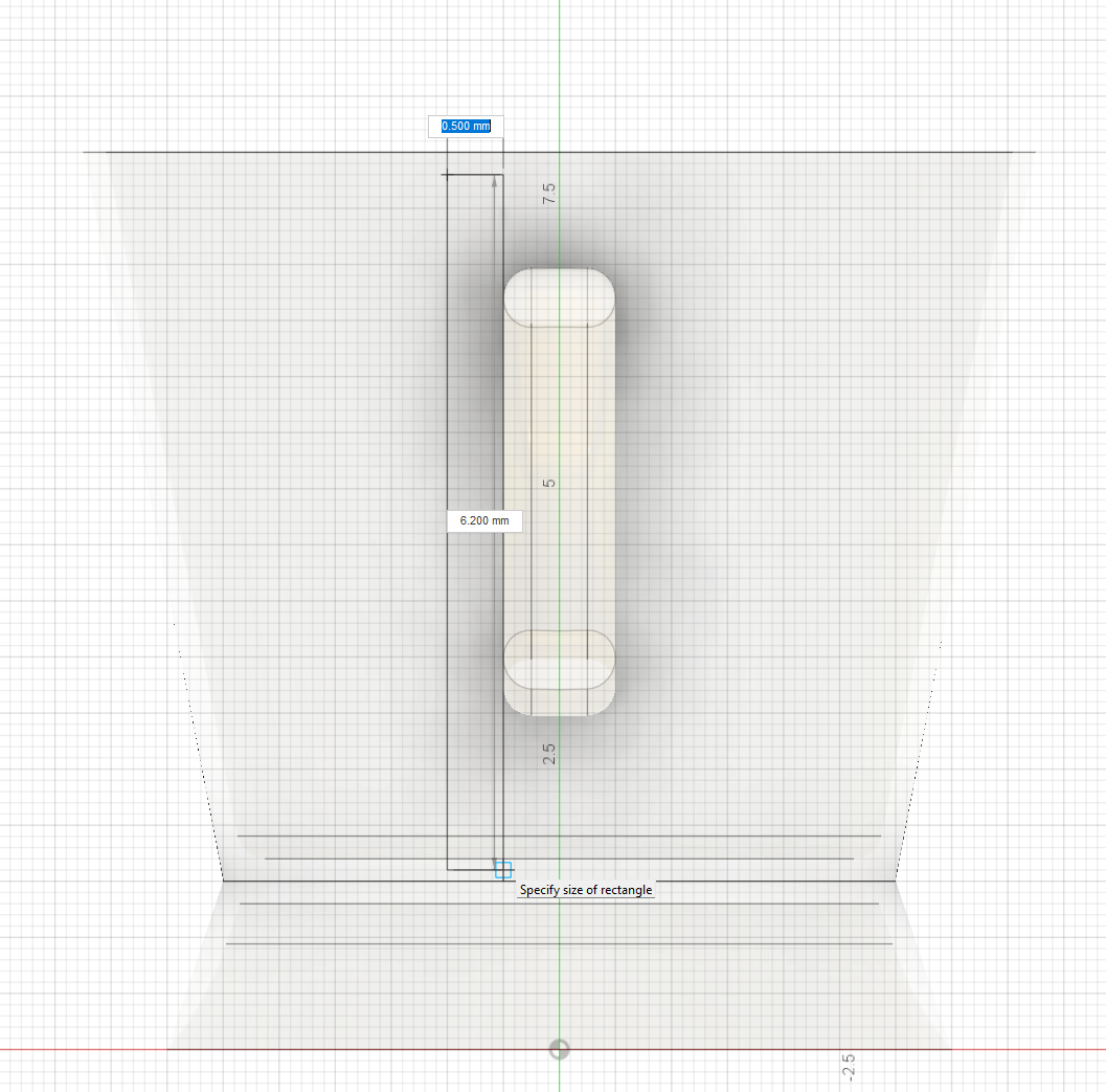
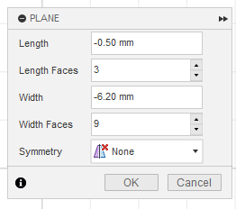
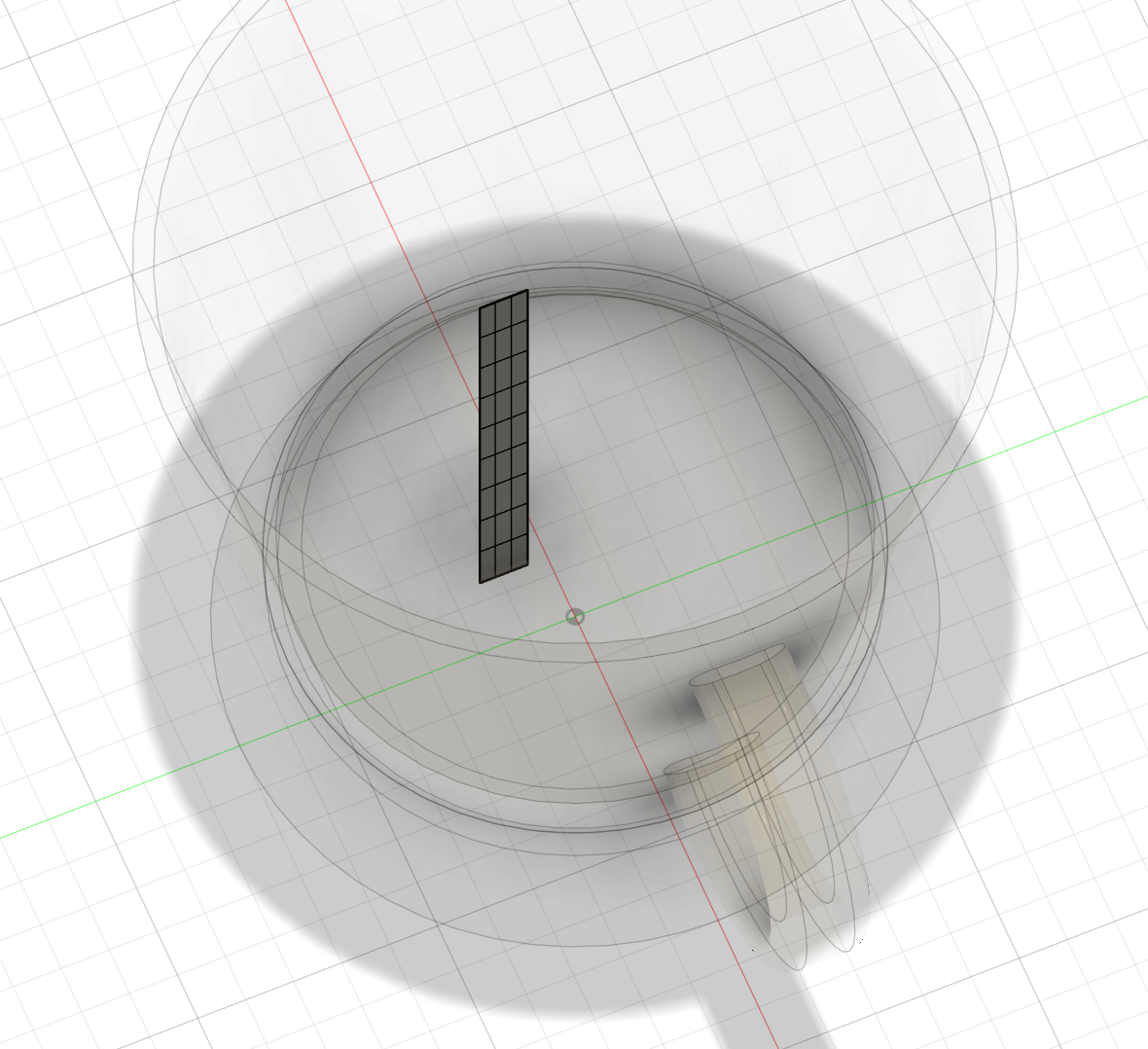
First, select the “Create form” tool. Next, select “Plane“. Select the YZ plane, and choose the “Left” face of the cube on the right side of the screen. Put the corners somewhere around the line shown in the fourth image. Change to the “Length Faces” to 3, and “Width Faces” to 9, and hit “Ok”.
Manipulating the Form
.png)
.png)
.png)
.png)
.png)
.png)
.png)
.png)
.png)
.png)
.png)
.png)
.png)
.png)
.png)
.png)
.png)
.png)
.png)
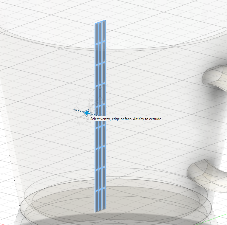
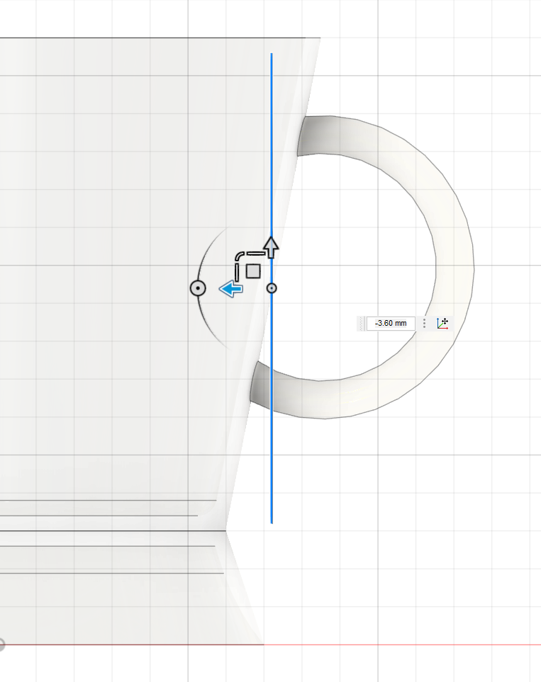
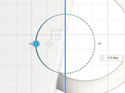
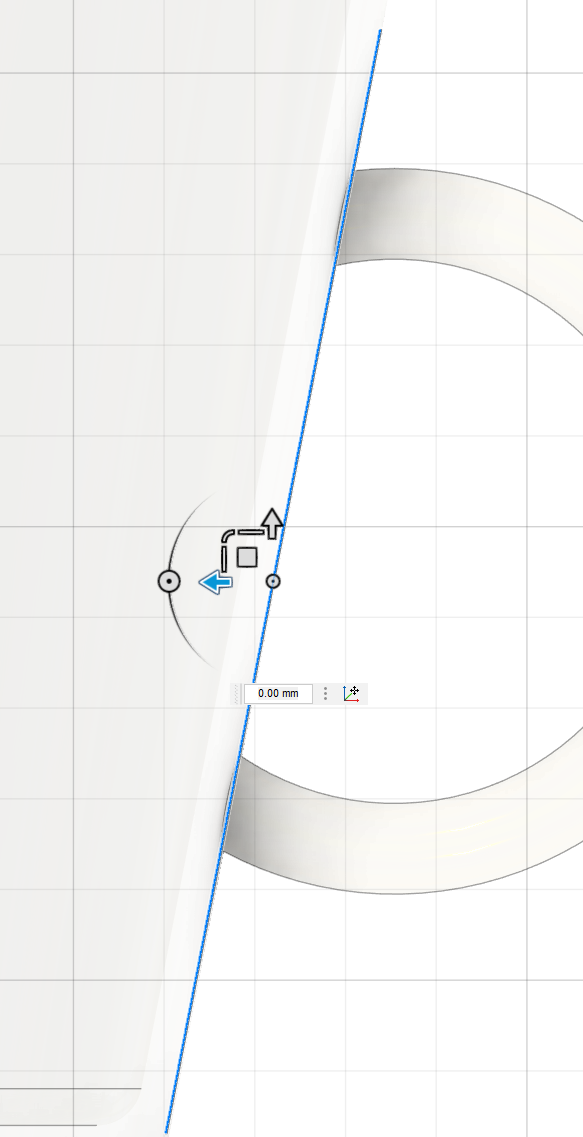
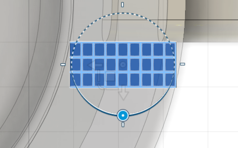
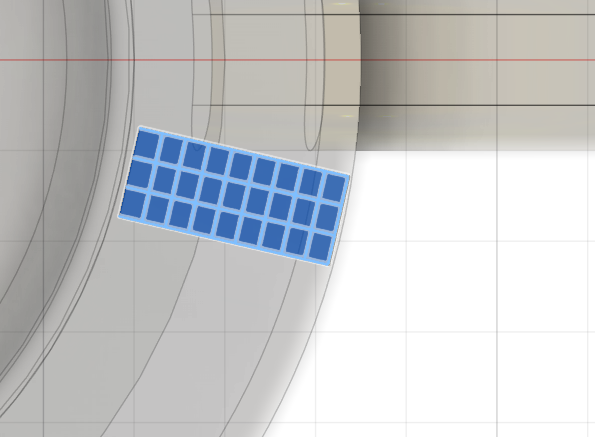
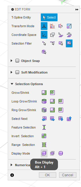
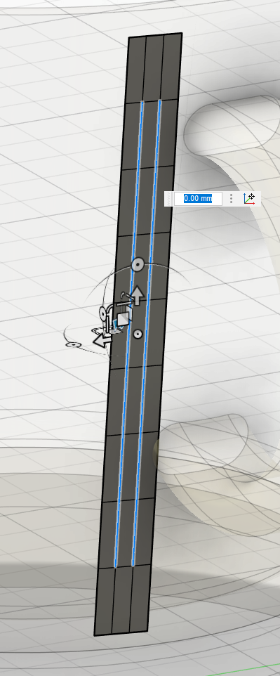
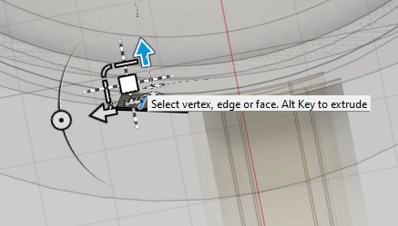
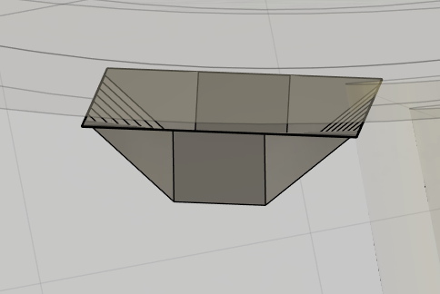
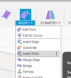
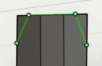
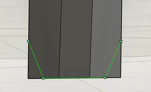
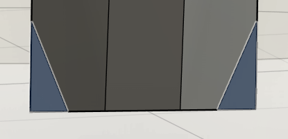
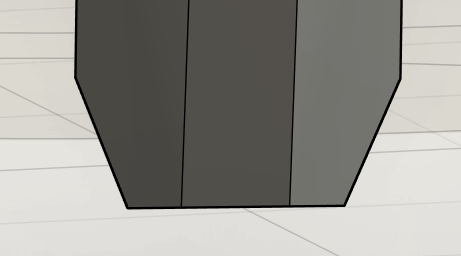
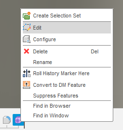
Using the box in the upper-right of your screen, move your view something like the first image. Select the whole grid, and move the view to make it easy to perceive how close the grid is to the cup. Then, select the “Modify” tool. Move the grid towards the handle using the arrow that restricts movement in one direction. It should look like the fourth picture. Use the outer circle shown below to rotate it, and make it parallel to the outermost line of the cup. Change to the top view, and rotate again to align the best as possible to the edge of the cup. Within the “Modify” tool, look at the “Selection Options” dropdown and change “Display Mode” to “Box Display”. Using shift, select the three lines shown in the tenth picture. Then, using the perspective box, get a perspective more on the top view side, and using the square moving in the XY plane, move the lines out. Select the “Insert Point” tool. Make corners like those shown in the fourteenth and fifteenth pictures, and try to make them as symmetric as possible, then hit “Ok”, and do the same for the bottom side. Then select the harsh faces like those in the sixteenth picture, right-click them, and delete them. You can do some additional tweaking, but warning: sometimes something looks right when you fix it from one perspective, but it doesn’t do what you wanted when you change your perspective. This will be increasingly important, as we manipulate more forms. Once you’re done, click “Finish Form”. If you ever want to edit this form later on, look at the timeline at the bottom of your screen, right-click the form, and click “Edit”, shown in the last image.
Make Snake Head
.png)
.png)
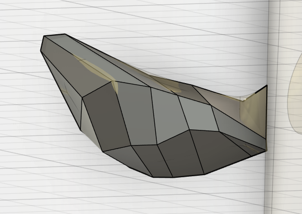
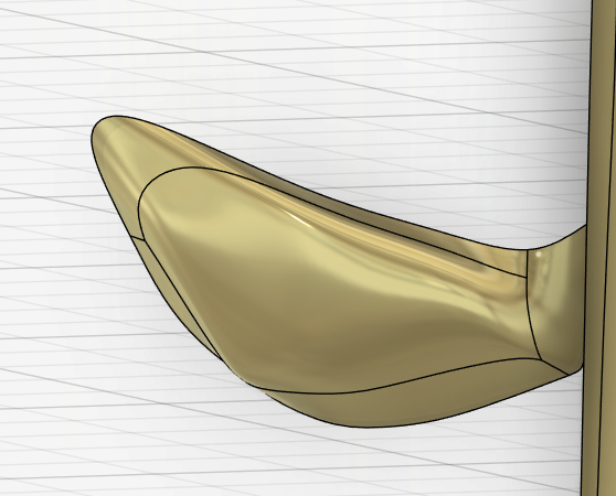
Use the same skills from the previous step, the base will remain plane, this time with “Length Faces” as 3, and the “Width Faces” as 6. First, you align the entire grid with the cup. Remember to change the “Display Mode” to “Box Display”. Then, modify each point using the “Edit Form” tool. You can also explore the other “Modify” tools if needed. The goal is a box display like the first image above. The smoothed-out should be something like this (Once the appearance is changed to “Gold - Polished”):
Make Transition Piece Forms
.png)
.png)
.png)
.png)
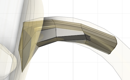
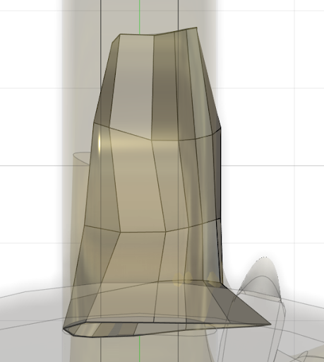
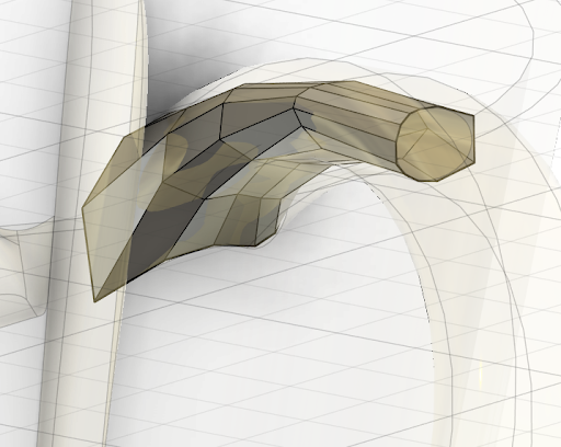
The transition pieces are in some ways harder. The starting piece is a cylinder. Start with 6 lines for the detail of the circle and four lines across the cylinder. Then, do your best to fit the same shape as the handle with the cylinder. After that, modify the points on the side nearer to the main stick to transition better. REMEMBER TO USE THE BOX DISPLAY. Without the box display, the structure can get really confusing. If you also want to see the smoothed-out version, you can also briefly use the “Control Frame Display” display. The goal box display is shown in the first three images. Personally, I found the bottom transition harder initially, but I flipped the entire view and tried to replicate what I did for the top, and this worked for me, however, it may be more confusing for others.
Make the Snake Body
.png)
.png)
.png)
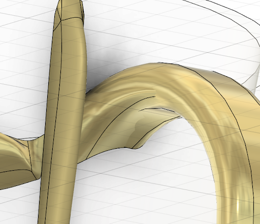
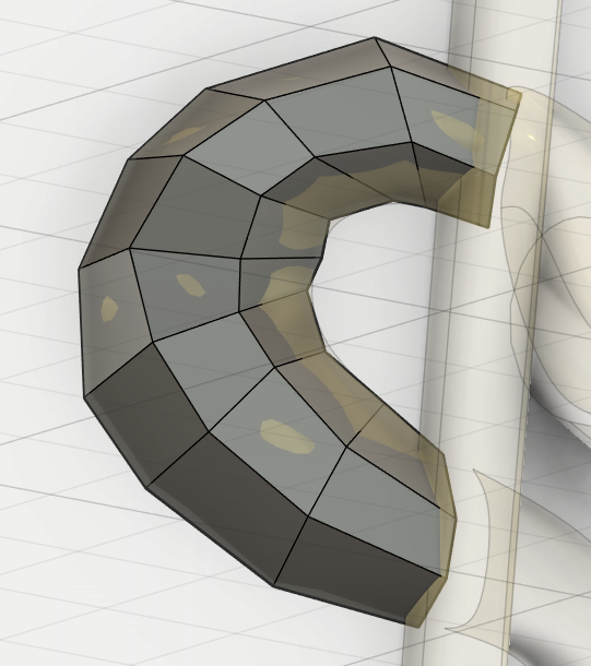
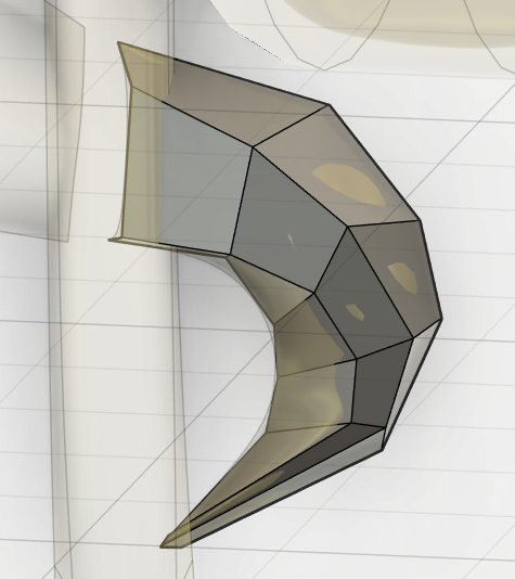
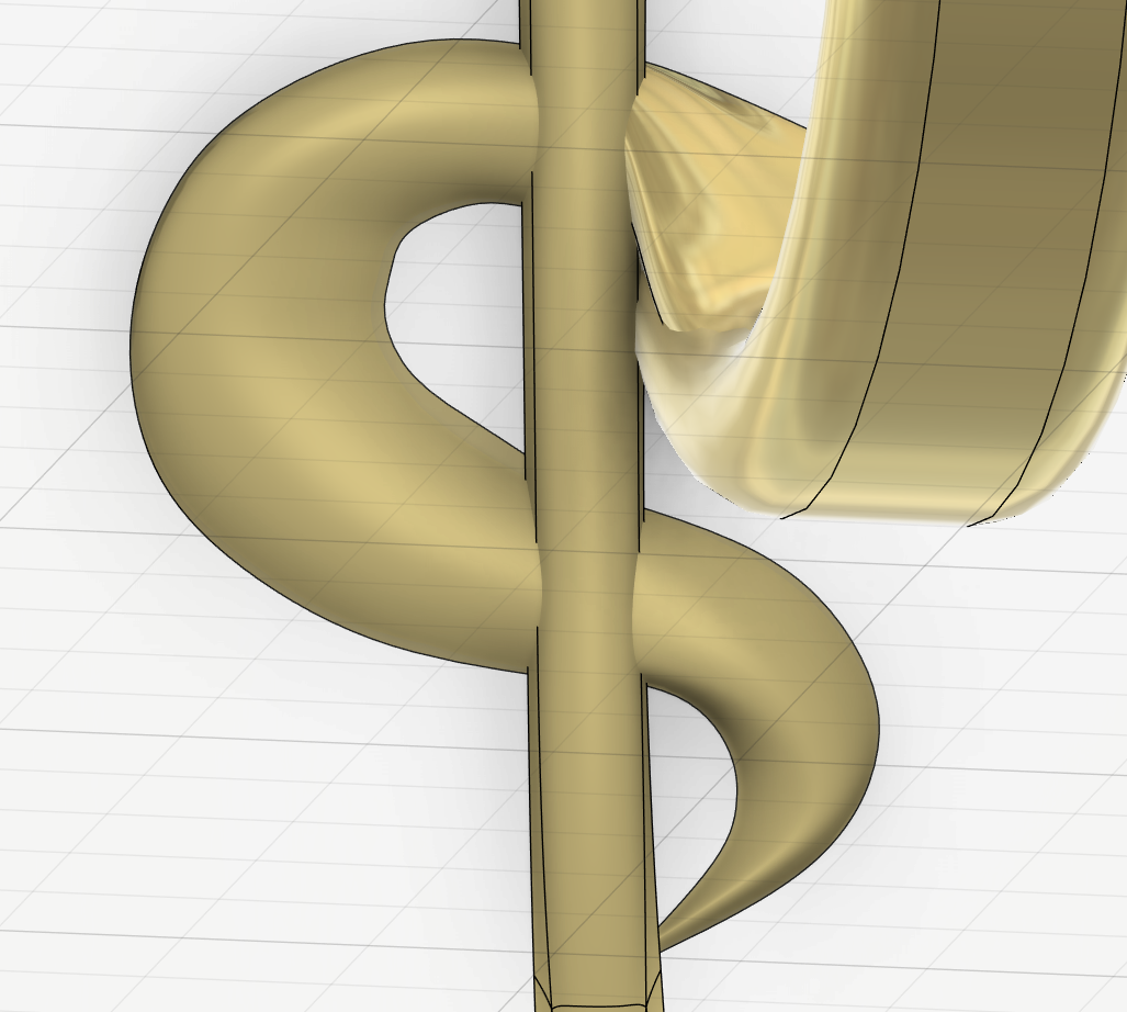
This will be more similar to the stick and snake’s head. The initial type will, again, be a plane with this time initially 2 for “Width Faces” and 8 for “Length Faces”. The number of width faces will increase, but you need to move every point individually this time, to make the curve. Once you make the initial curve, you can expand it by selecting edges and holding Alt to make the new planes. Both curves work like this, progressively getting smaller. (REMEMBER: BOX DISPLAYS) The goal box displays are shown in the first two images. Smoothed-out goal is shown in the last image.
Rendering the Cup
.png)
.png)
.png)
.png)
.png)
.png)
.png)
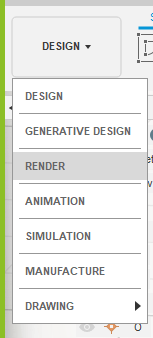
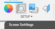
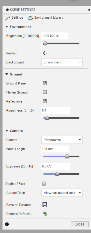
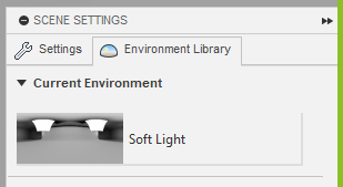
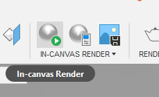
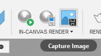
This is definitely the easiest part! Congrats on getting this far!! First, go to the upper-left corner of your screen and change to the “Render” workspace. Select the “Scene Settings” tool. A lot of this is personal preference, but my settings (for the introduction render) are shown in the third and fourth images. Select “In-canvas Render”. The initial setting is usually the grey arrow at “Excellent” - for my settings, I changed this to “Infinite” and watched carefully until I was satisfied with the result. (For me, I waited until the 600 range but this is dependent on your use for this and your computer strength) When you are satisfied, select the “Capture lmage” tool, and save it (in whatever format you want (I used png for the introduction photo)) to your computer wherever you want.
CONGRATULATIONS!
You're done! Congrats again for finishing! Remember to save!