GroupONE Smart Home
.jpeg)
.jpeg)
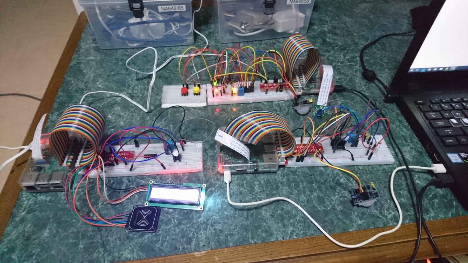
Welcome! This Raspberry Pi project is a "smart home" management system, which is able to measure various data such as temperature, humidity and light values at various parts of the house. This Instructable will cover the setup for the entrance and living room as well as 1 bedroom.
The data is sent out and processed through IBM Bluemix before being returned to Node-Red, upon which then performs the necessary actions such as turning on the lights when it is dark and motion is detected.
Users can view the data collected via a Dashboard in Node-Red that shows the current measurement values in addition to a graphical representation of a gauge and a historical graph. The Dashboard also includes additional features such as a clock that displays the current data and time and switches to remotely control various electrical appliances, which are represented as LEDs and a buzzer.
Lastly, there is a house alarm system comprising of an MFRC 522 RFID card reader, a buzzer, a motion sensor and a 16x2 LCD display. The status of the RFID house alarm system is also displayed on the dashboard. What makes this house alarm system special is that it can read messages given to it such as “Welcome Home” to show that access is granted or “Access Denied” to show that access is denied. When there is motion detected while the lights are turned off, the buzzer will ring and an email will be sent to the user. When the alarm is dismissed another email will be sent.
Preparing the Necessary Hardware


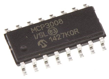
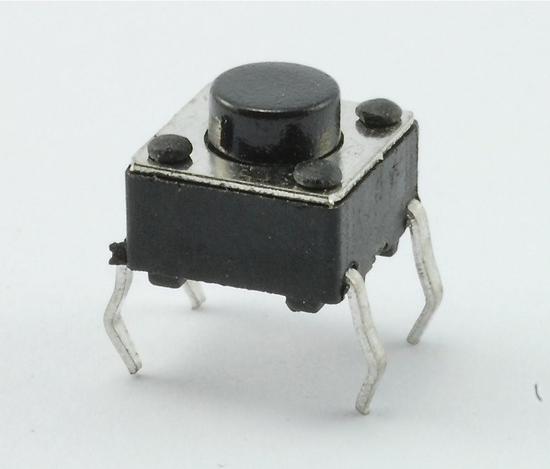
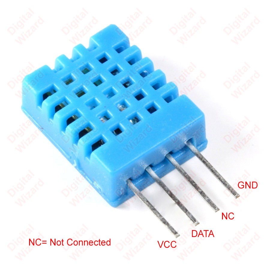
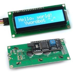
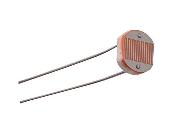

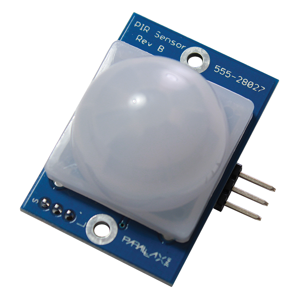
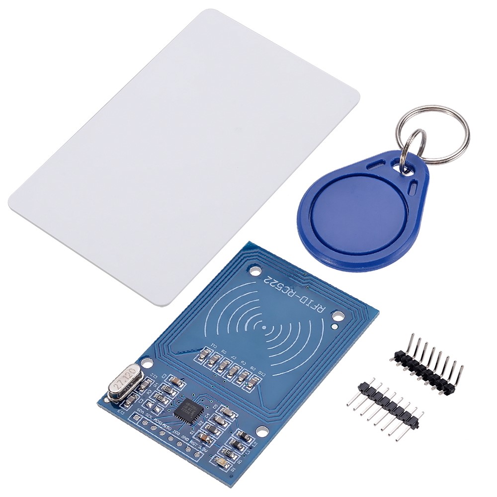
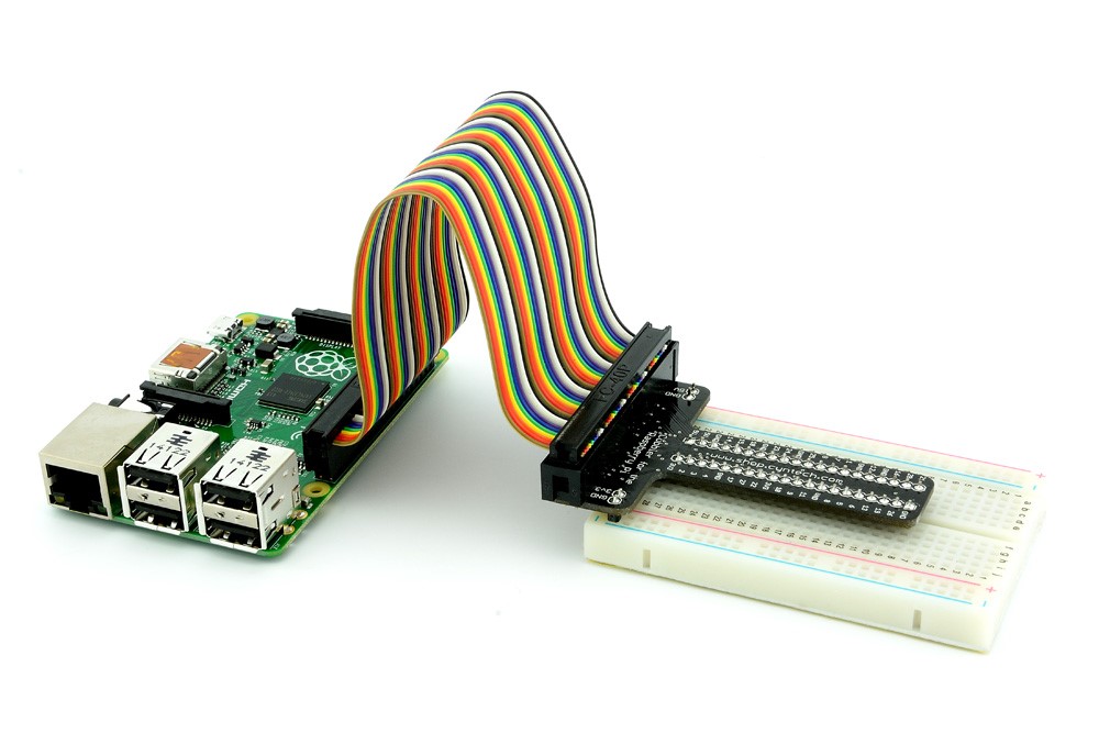
Ensure that you have all of the following before proceeding. The quantity of each item required is placed in brackets.
- Raspberry Pi 3 Model B (3 units)
- Breadboard (3 units)
- Half breadboard (1 unit)
- T-Cobbler kit (3 units)
- DHT11 Temperature and Humidity Sensor (3 units)
- LED (5 units)
- 220 ohms Resistor (5 units)
- 10K ohms Resistor (7 units)
- HC-SR501 PIR Motion Sensor (2 units)
- Buzzer (1 unit)
- I2C LCD Screen (1 unit)
- RFID / NFC MFRC522 Card Reader Module (1 unit)
- RFID Card (2 units)
- Light-Dependant Resistor (LDR) (2 units)
- Analog-to-Digital Converter (3 units)
- Male to male jumper cables (At least 80 units)
- Male to female jumper cables (At least 10 units)
- Power Adapter / USB to micro USB cable (3 units)
- RJ45 LAN cable (3 units)
Entrance Hardware #1
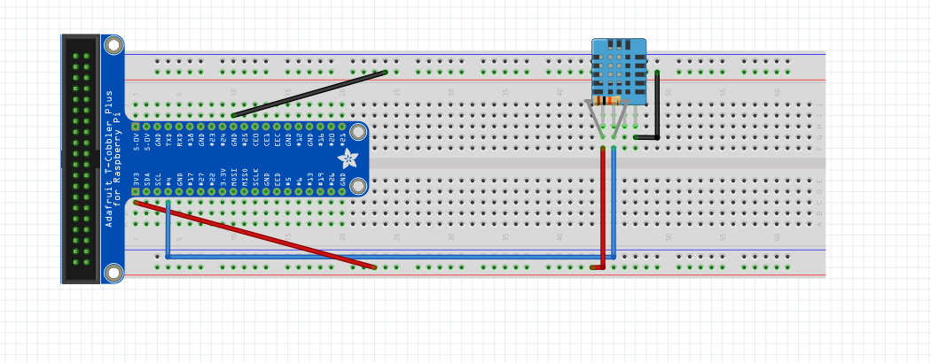
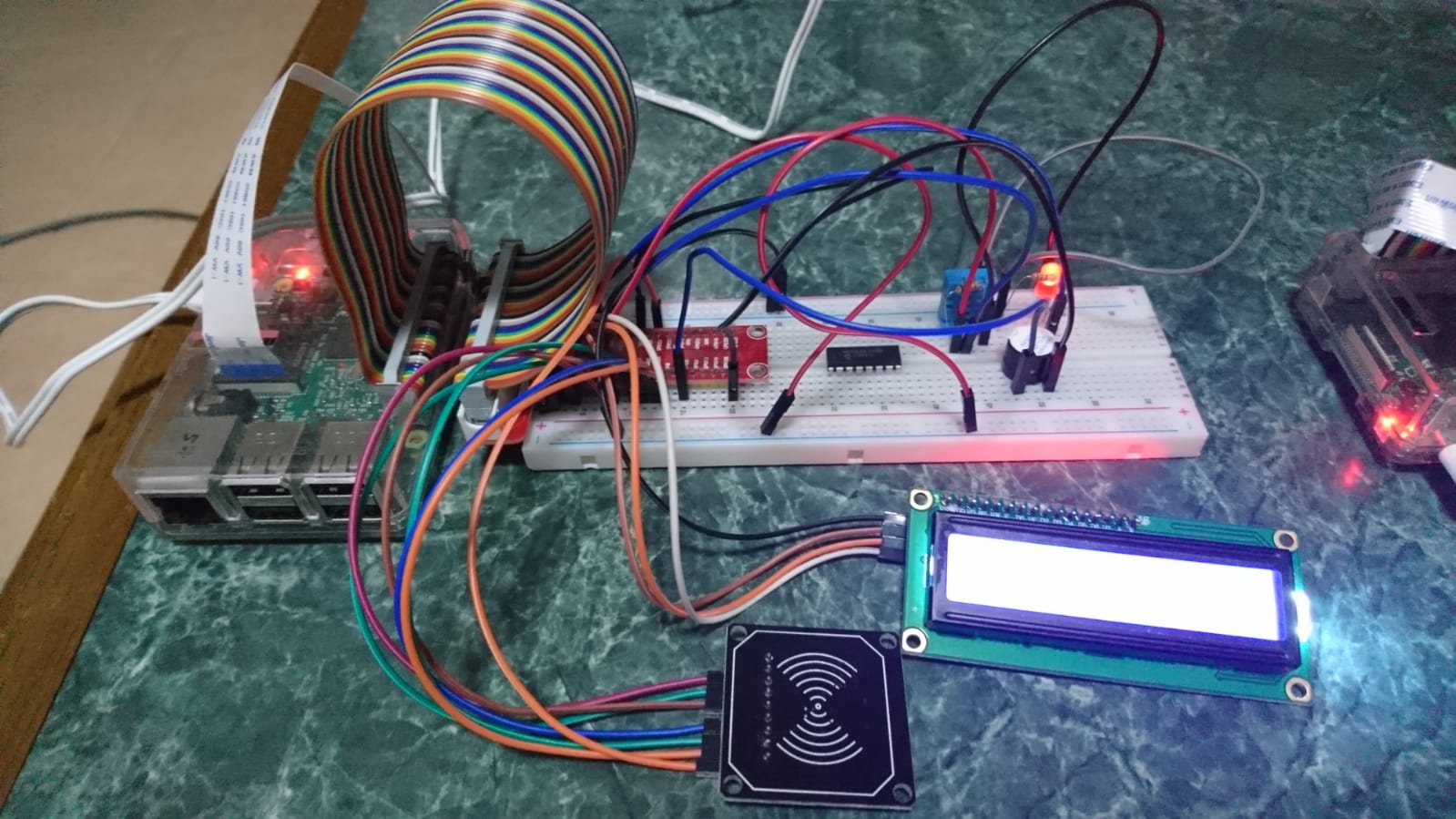
Now that we have gathered the essential items, it's time to begin setting up the hardware for the first part of our project - the entrance. Connect the DHT11 sensor, 10k ohm resistor and jumper cables as shown.
Entrance Hardware #2
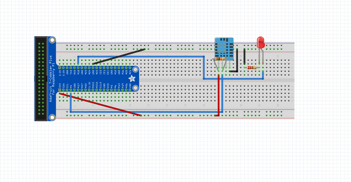
Next, install the LED bulb, 2 more jumper cables and a 220 ohms resistor.
Entrance Hardware #3
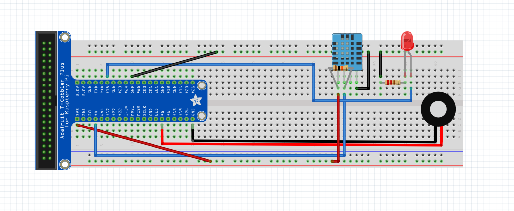
Connect the buzzer and its 2 jumper cables as shown.
Entrance Hardware #4
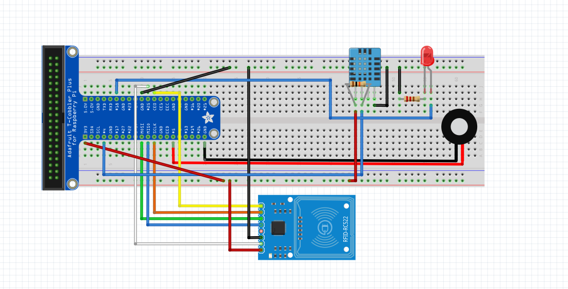
Using 7 male-to-female jumper cables, install the RFID / NFC MFRC522 card reader module.
Entrance Hardware #5
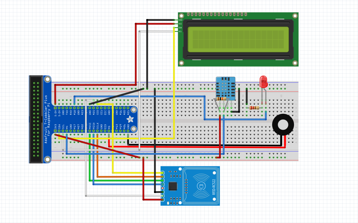
Add the I2C LCD screen and its 4 male-to-female jumper cables. This concludes the setting up of the hardware for the entrance.
Living Room Hardware #1

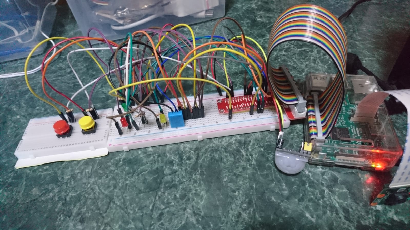
Start on another Raspberry Pi, breadboard and T-Cobbler kit for this step. The orange wire is for 3v3 supply while the grey wire is for GND supply. Use the 330Ω resistor for the LEDS, connect the green wires of yellow LED to GPIO23 and red LED to GPIO24. Connect the brown wires of both LEDs to the same row as the grey wire (GND).
Living Room Hardware #2
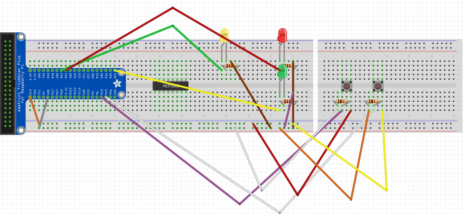
Connect the DHT11 sensor as shown in the picture above. Use a 10k Ω resistor this time for the DHT11 sensor, connect the blue wire to GPIO4. Connect the red wire to the same row as the orange wire (3v3) and the black wire to the same row as the grey wire (GND).
Living Room Hardware #3
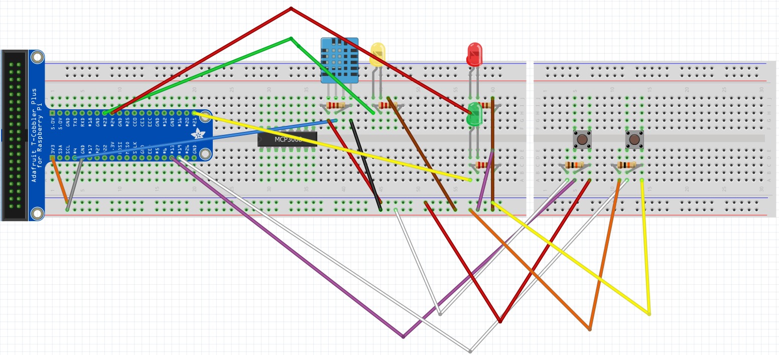
Connect the DHT11 sensor. Use a 10k Ω resistor this time for the DHT11 sensor, connect the blue wire to GPIO4. Connect the red wire to the same row as the orange wire (3v3) and the black wire to the same row as the grey wire (GND).
Living Room Hardware #4
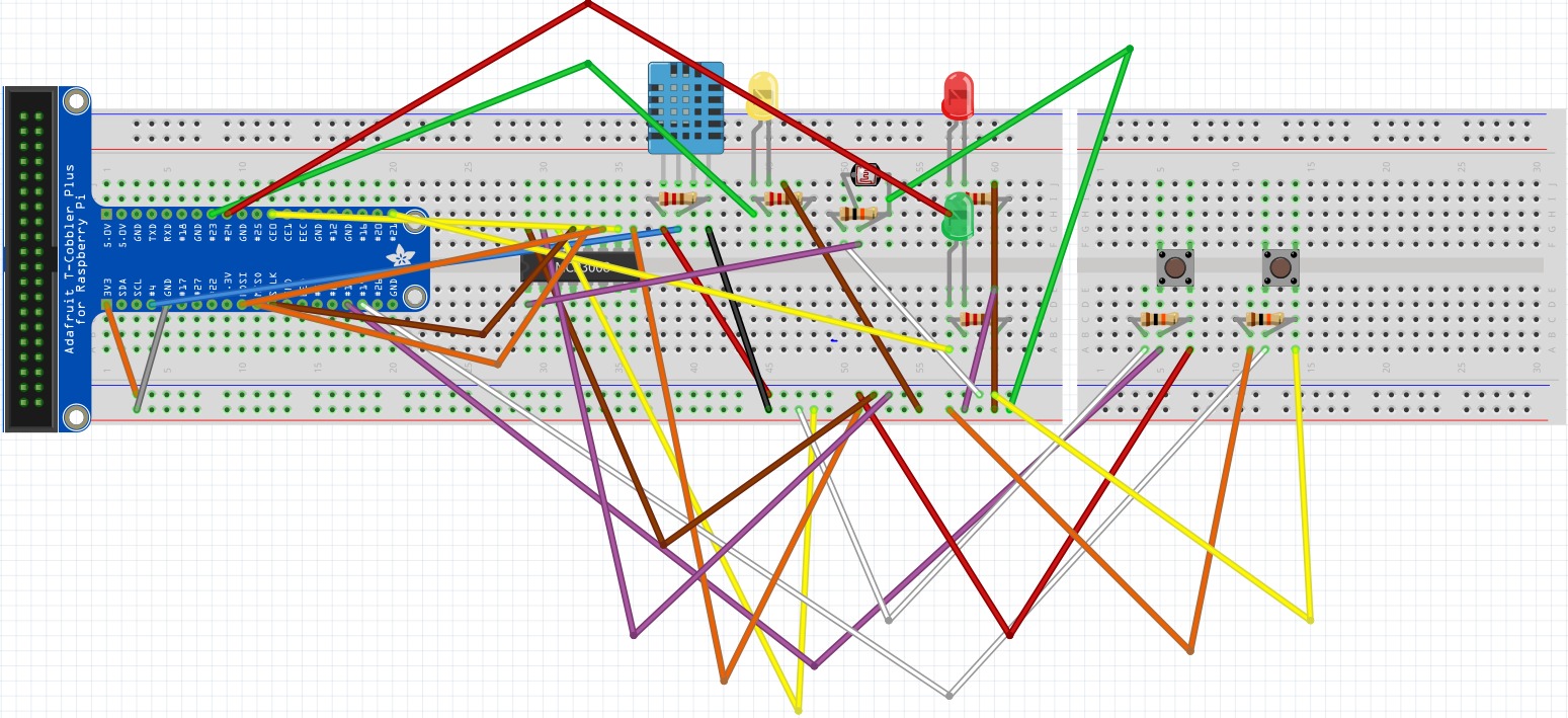
Now, install the Light Dependant Resistor, its 10k ohms resistor along with the necessary jumper cables.
Living Room Hardware #5
.jpeg)
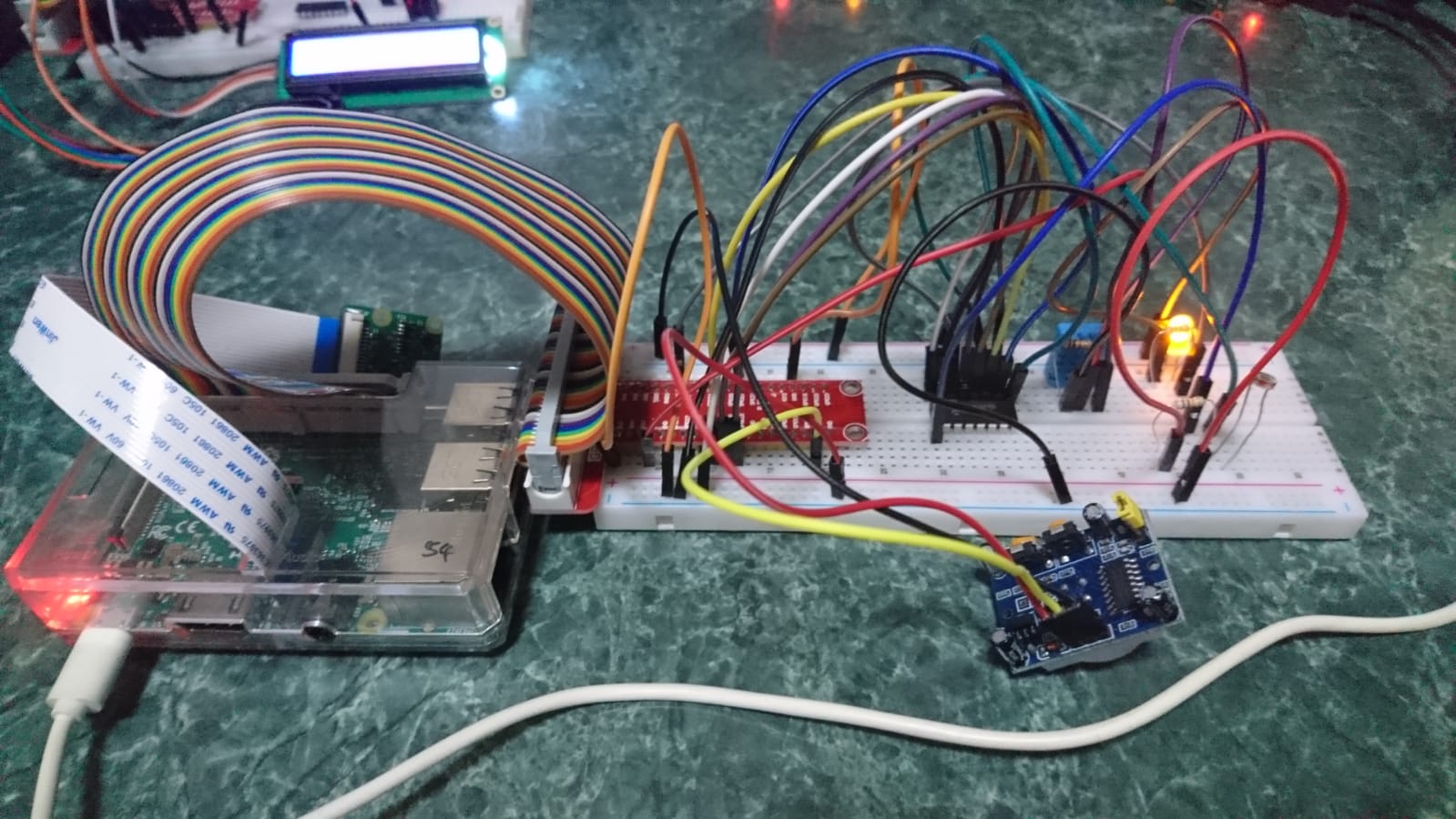
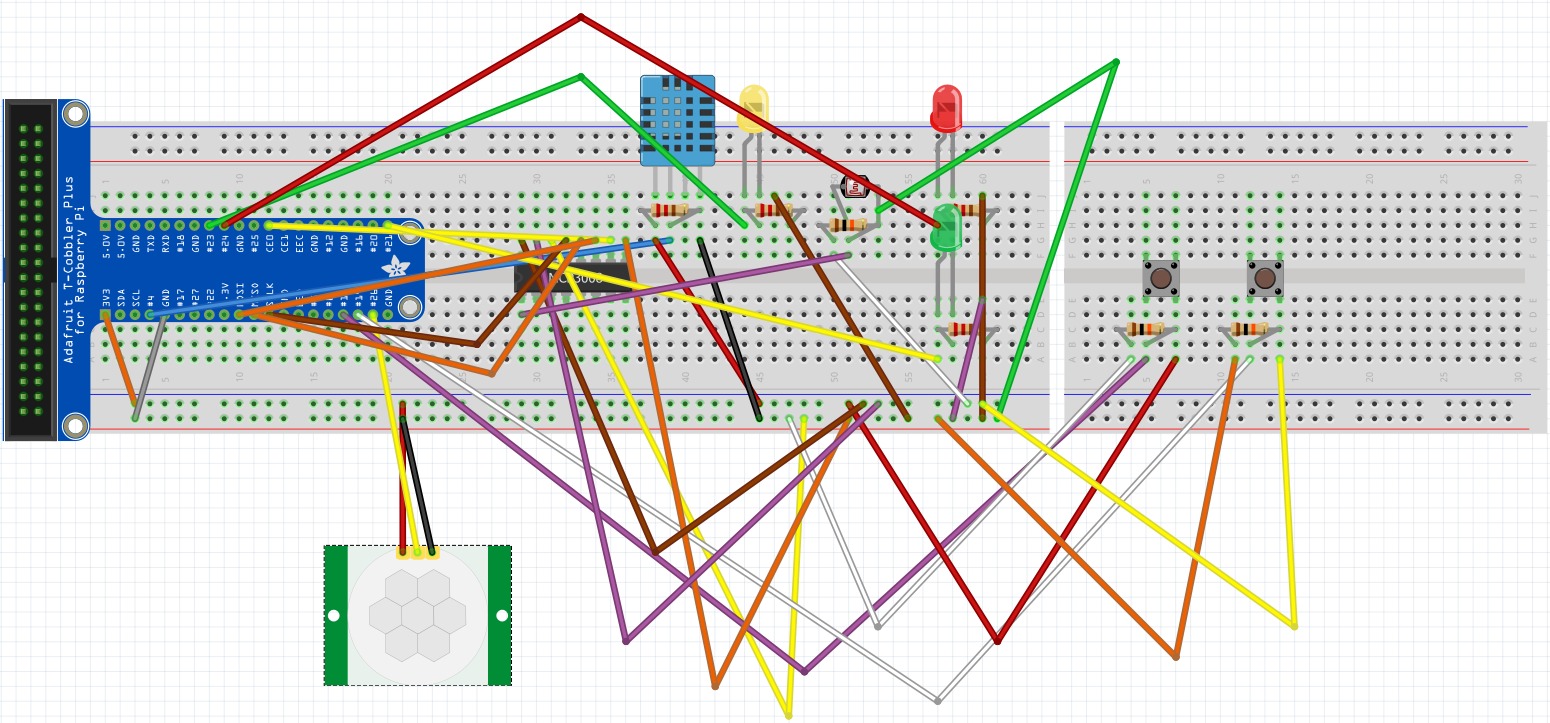
Connect the PIR Motion Sensor as shown in the picture above. Connect the yellow wire to GPIO26. Connect the red wire to the same row as the orange wire (3v3) and the black wire to the same row as the grey wire (GND). You're now done with setting up the living room hardware. One more to go!
Bedroom Hardware #1
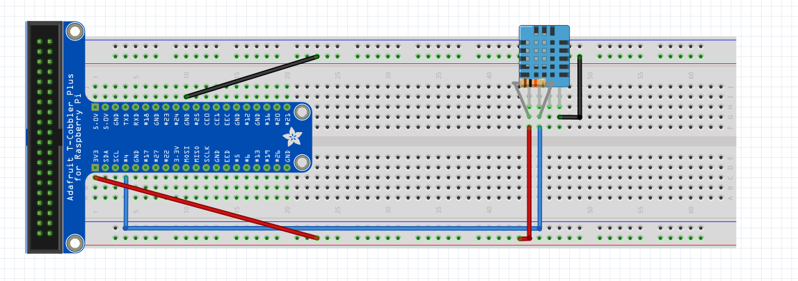
Again, start on another Pi, breadboard and T-Cobbler kit. Moving on to the bedroom: start with adding the male-to-male jumper cables, 10k ohms resistor and DHT11 sensor according to the diagram above.
Bedroom Hardware #2
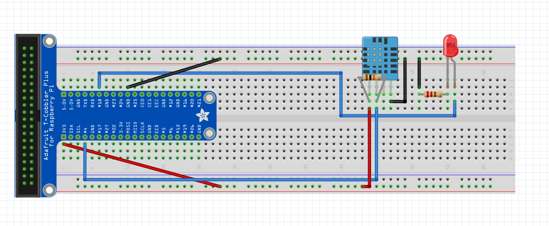
Now add the LED bulb, 2 more jumper cables and a 220 ohms resistor.
Bedroom Hardware #3
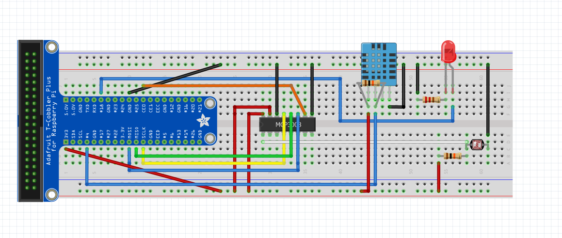
Connect the MCP3008 Analog-to-Digital converter and its respective jumper cables. Add the Light Dependant Resistor and its 10k ohms resistor as well.
Bedroom Hardware #4
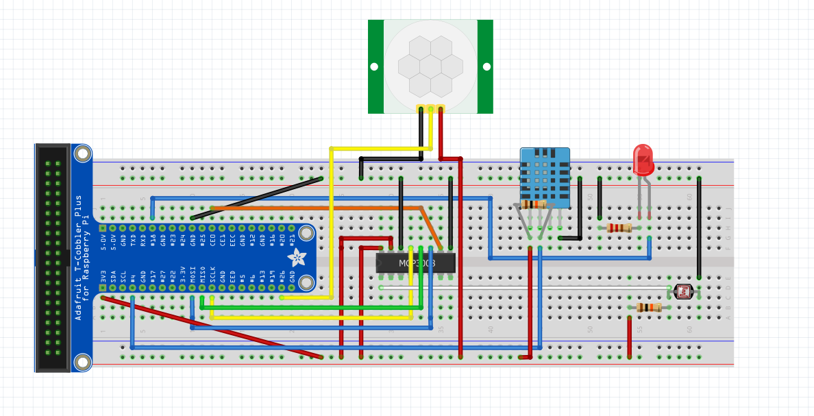.PNG)
Connect the motion sensor using 3 male to female jumper cables and you're done with the hardware setup for the bedroom!
Install IBM Watson Node-RED Nodes on RPi
Open a Terminal window and
install the following Node-RED nodes on your RPi:
sudo npm i -g node-red-contrib-ibm-watson-iot
Once installation is successful, reboot your RPi
sudo reboot now
Update Node-RED on RPi
Open a Terminal window and update Node-RED on your RPi
sudo npm install -g --unsafe-perm node-red
Install Additional Node-RED Modules on RPi
In order for the flows imported in the next step to work, the following modules must be installed as well.
node-red-contrib-moment (to format time)
node-red-dashboard (for dashboard)
node-red-contrib-telegrambot (for telegram bot)
node-red-node-daemon (for RFID, follow the link below for instructions)
https://developer.ibm.com/recipes/tutorials/reading-rfid-mifare-cards-into-watson-iot-platform-using-your-raspberry-pi-3/
node-red-contrib-i2clcd (for LCD, follow the link below for instructions)
https://github.com/johnty/node-red-contrib-i2clcd
Starting Node-Red and Mosquitto
Open a Terminal window and start Node-RED on your RPi
mosquitto
Open another Terminal window and start Node-RED on your RPi
node-red start
Import Flows for Entrance RPi
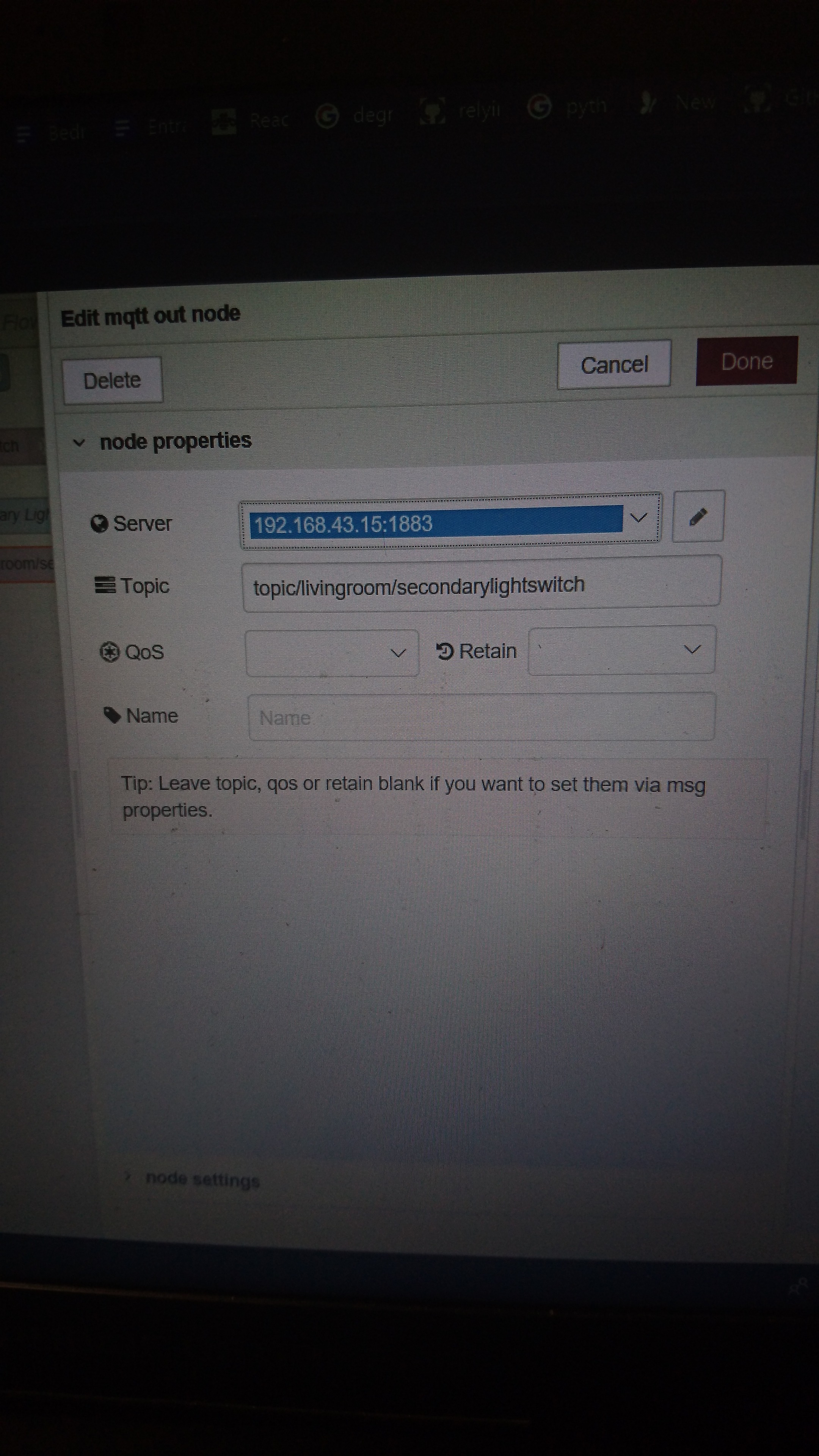
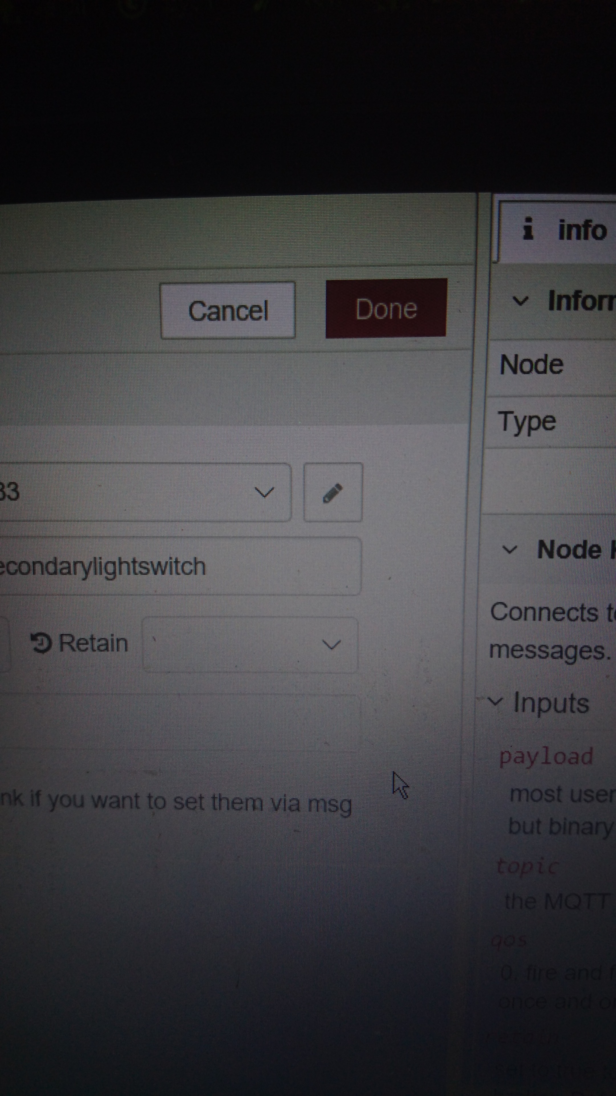
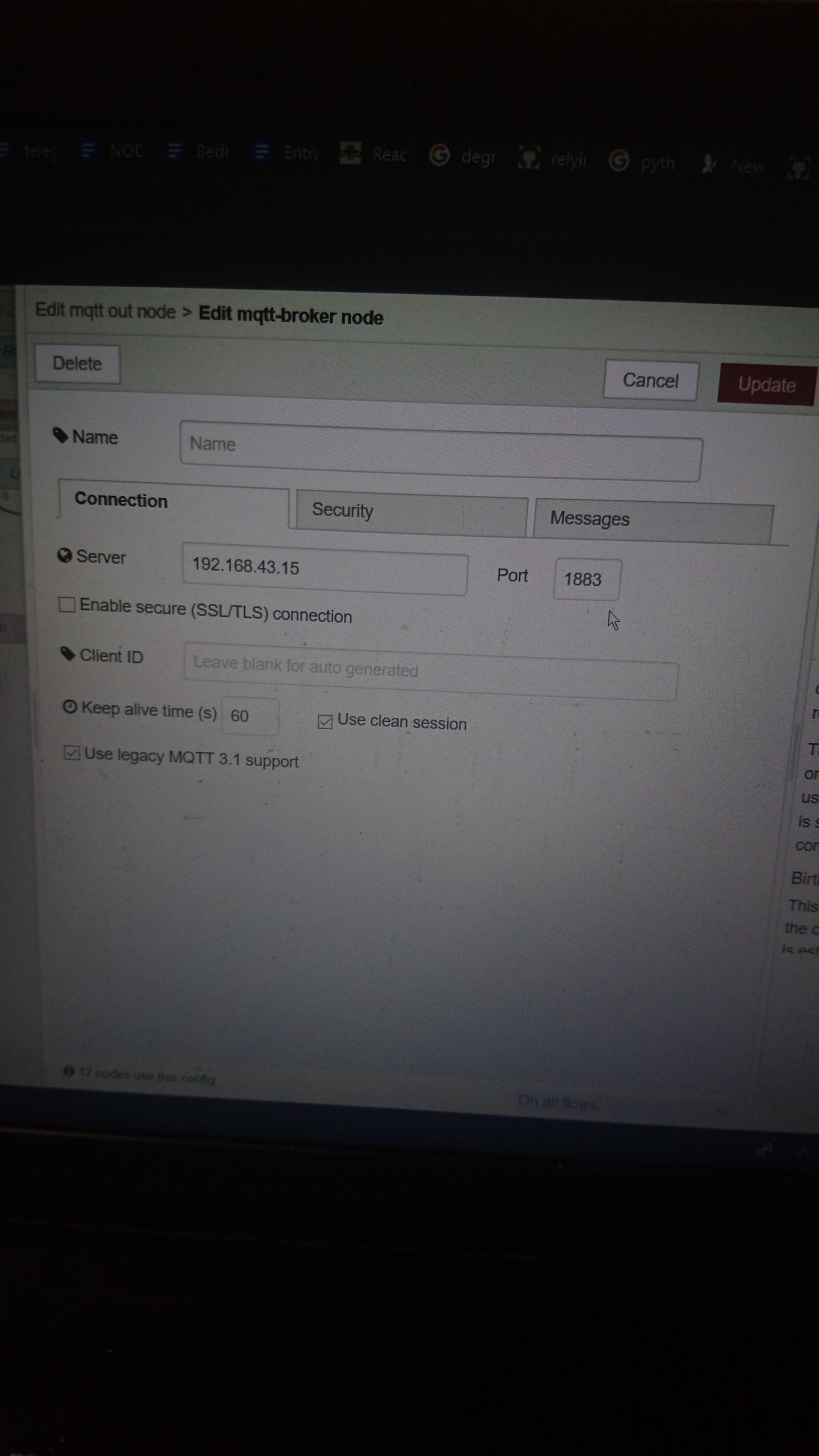
Click on the hamburger menu and go to Import > Clipboard
Paste in the code in the link below and click Import
https://pastebin.com/raw/a7UWaLBt
Click on an MQTT out node
Click on the pen icon
Enter the IP address of the Entrance RPi in the Server field
Click on Update. All other MQTT nodes on the same flow will be updated.
Import Flows for Living Room RPi
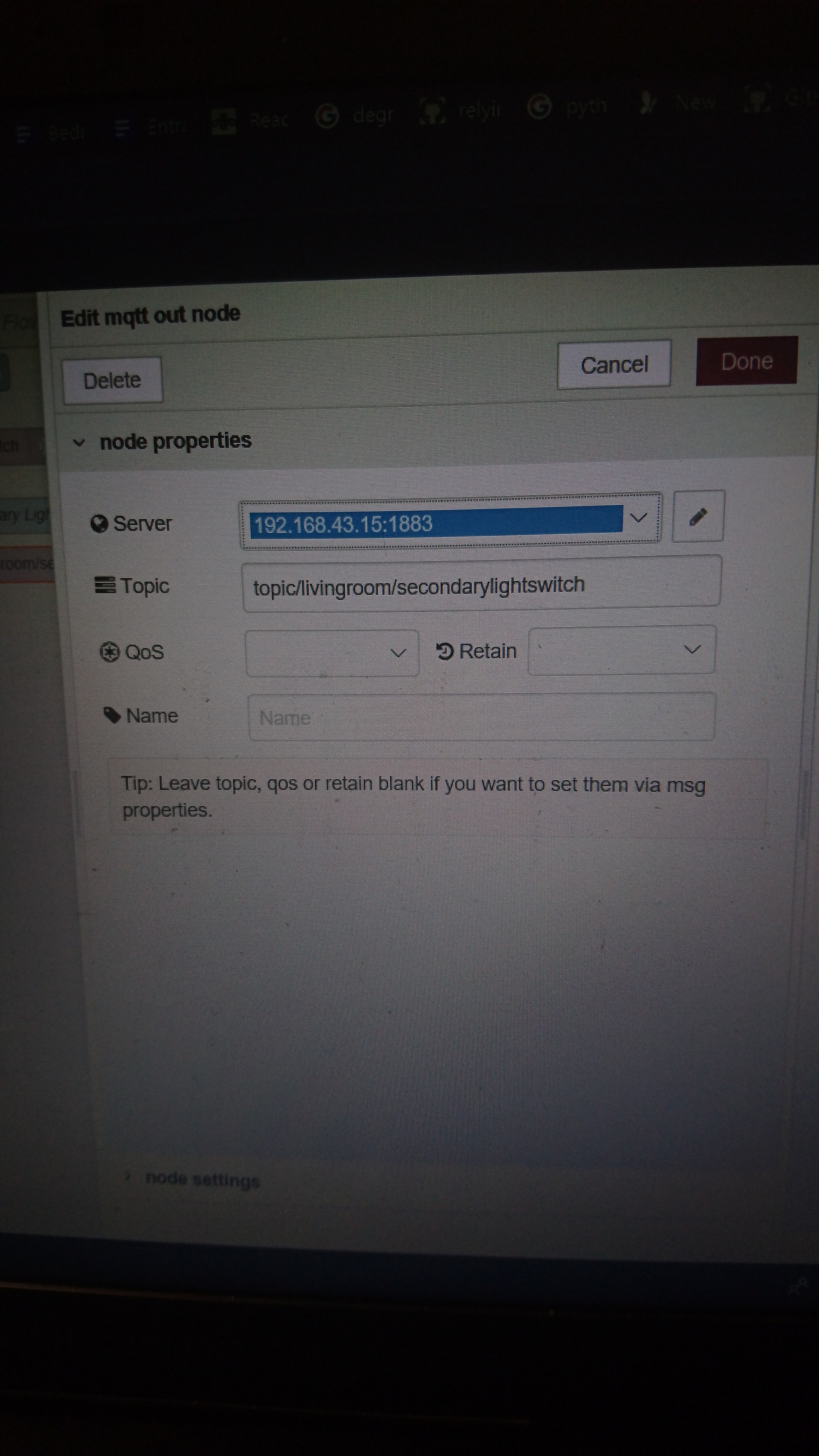
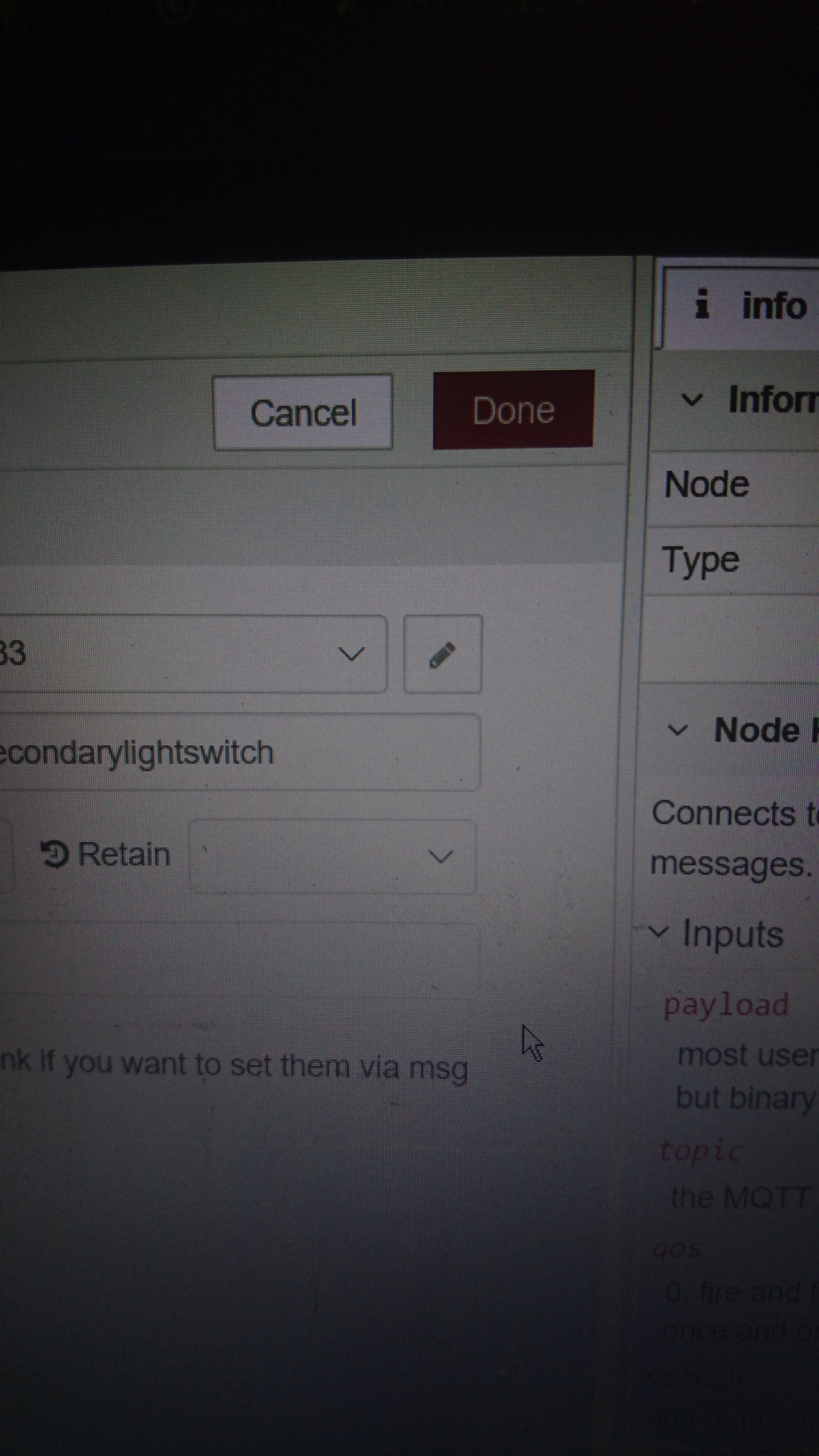
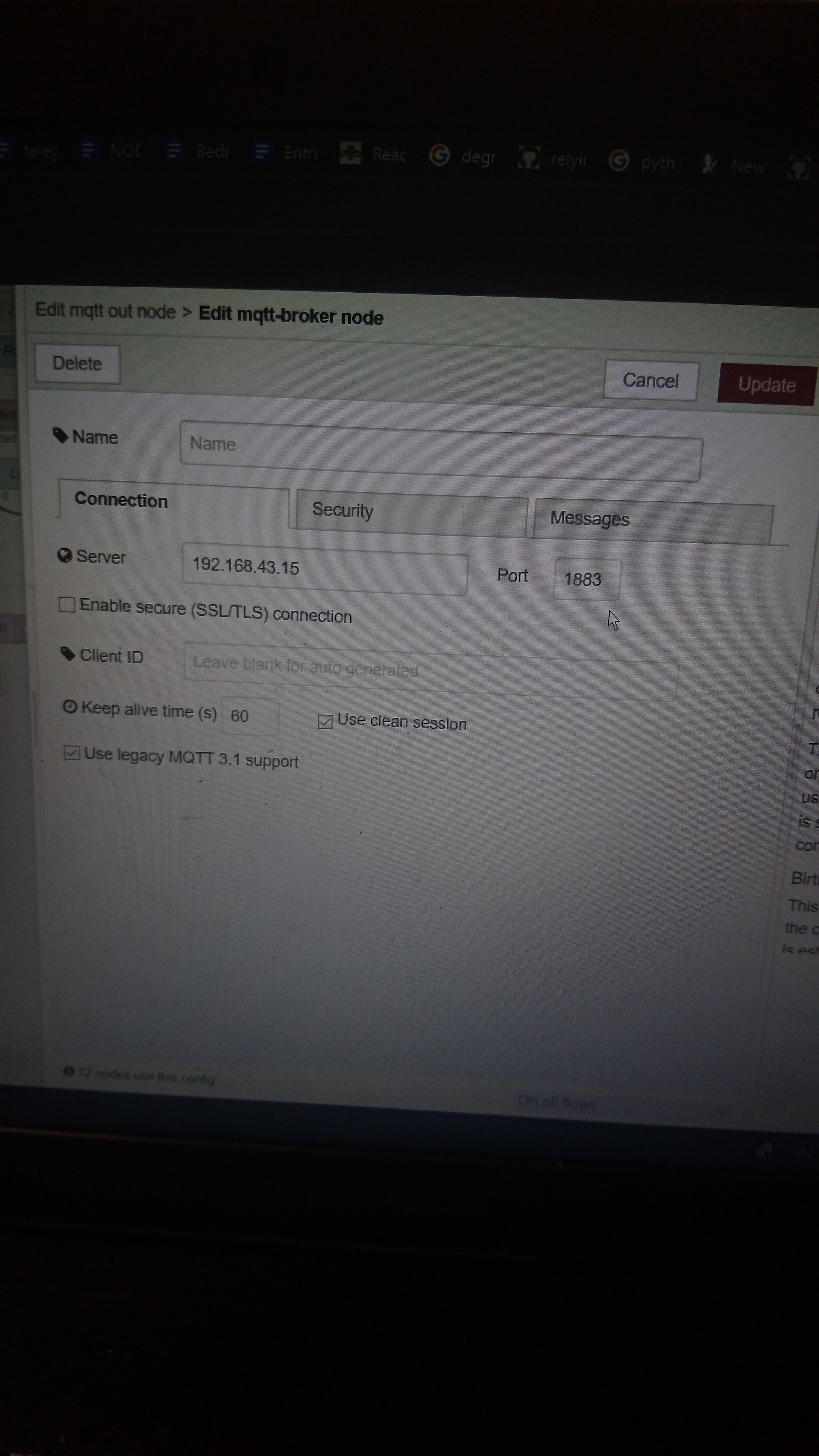
Click on the hamburger menu and go to Import > Clipboard
Paste in the code in the link below and click Import
https://pastebin.com/raw/vdRQP6aa
Click on an MQTT out node
Click on the pen icon
Enter the IP address of the Living Room RPi in the Server field
Click on Update. All other MQTT nodes on the same flow will be updated.
Import Flows for Bedroom RPi
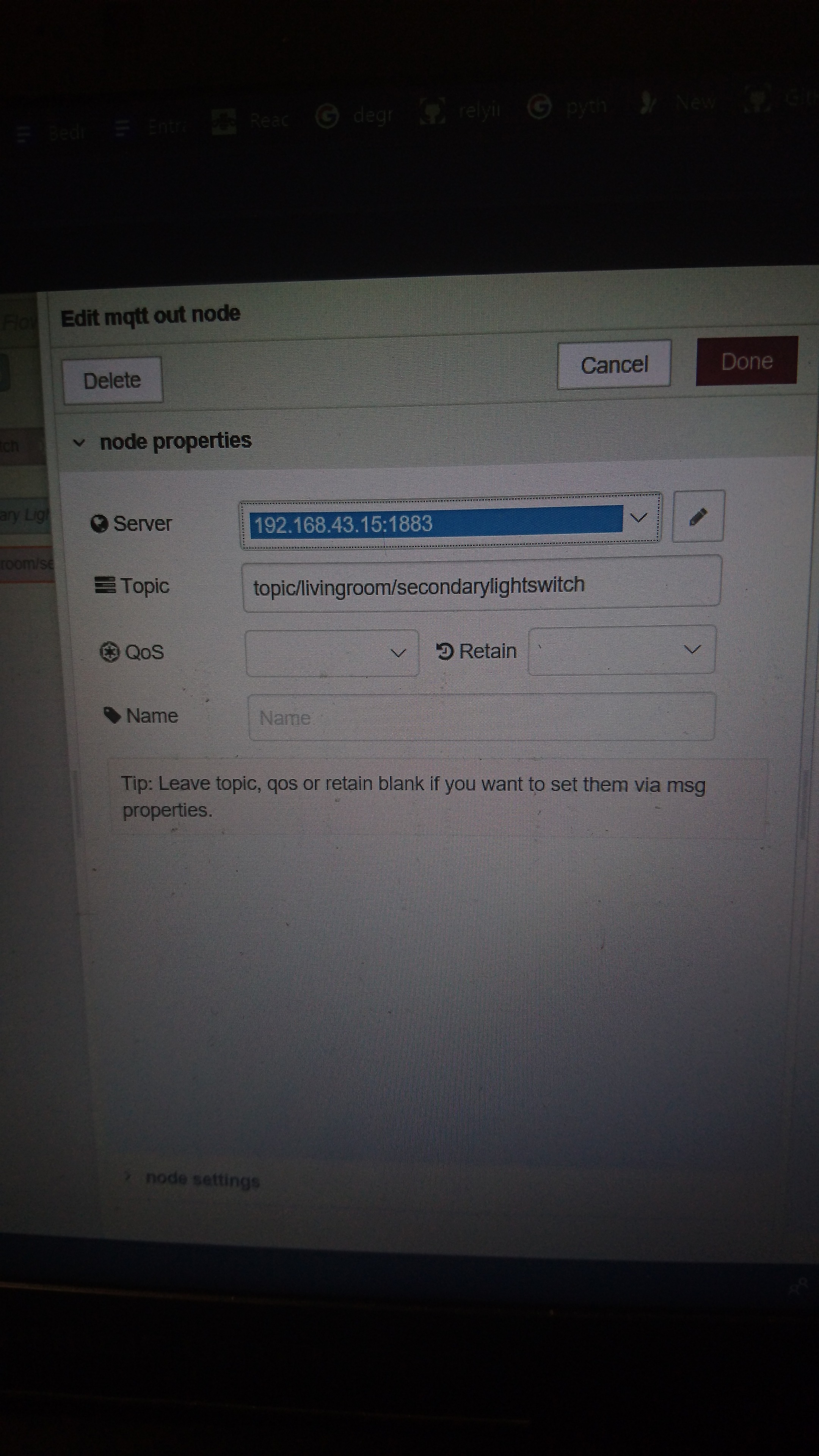
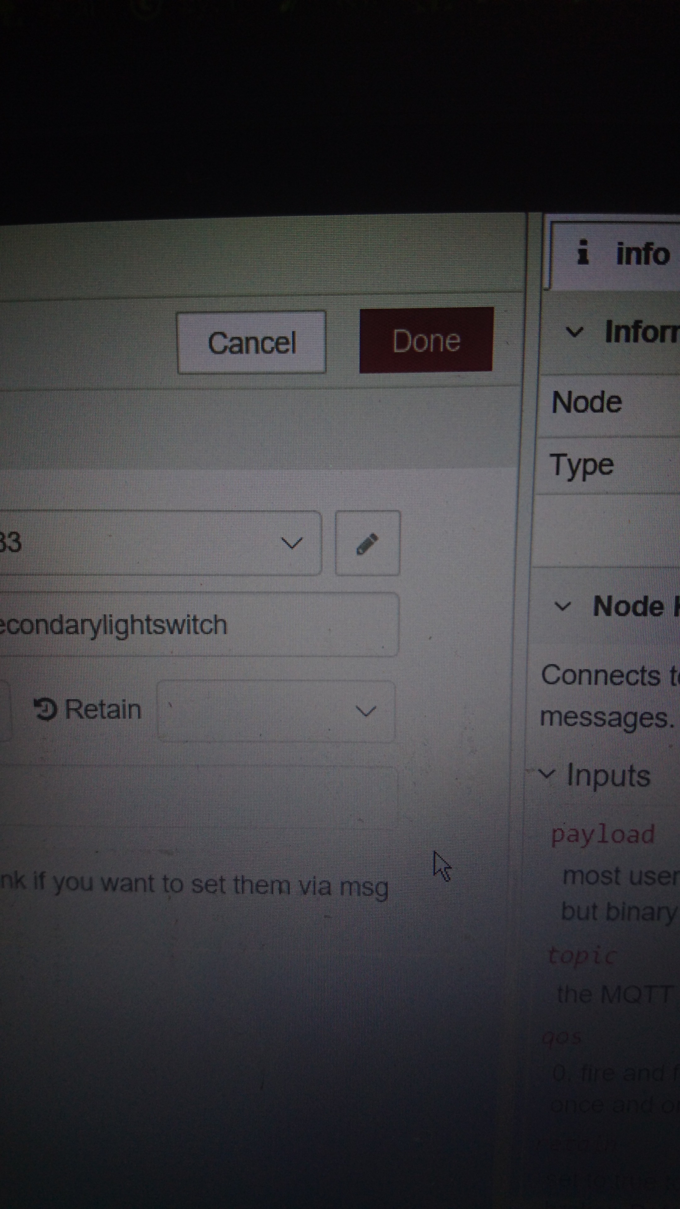
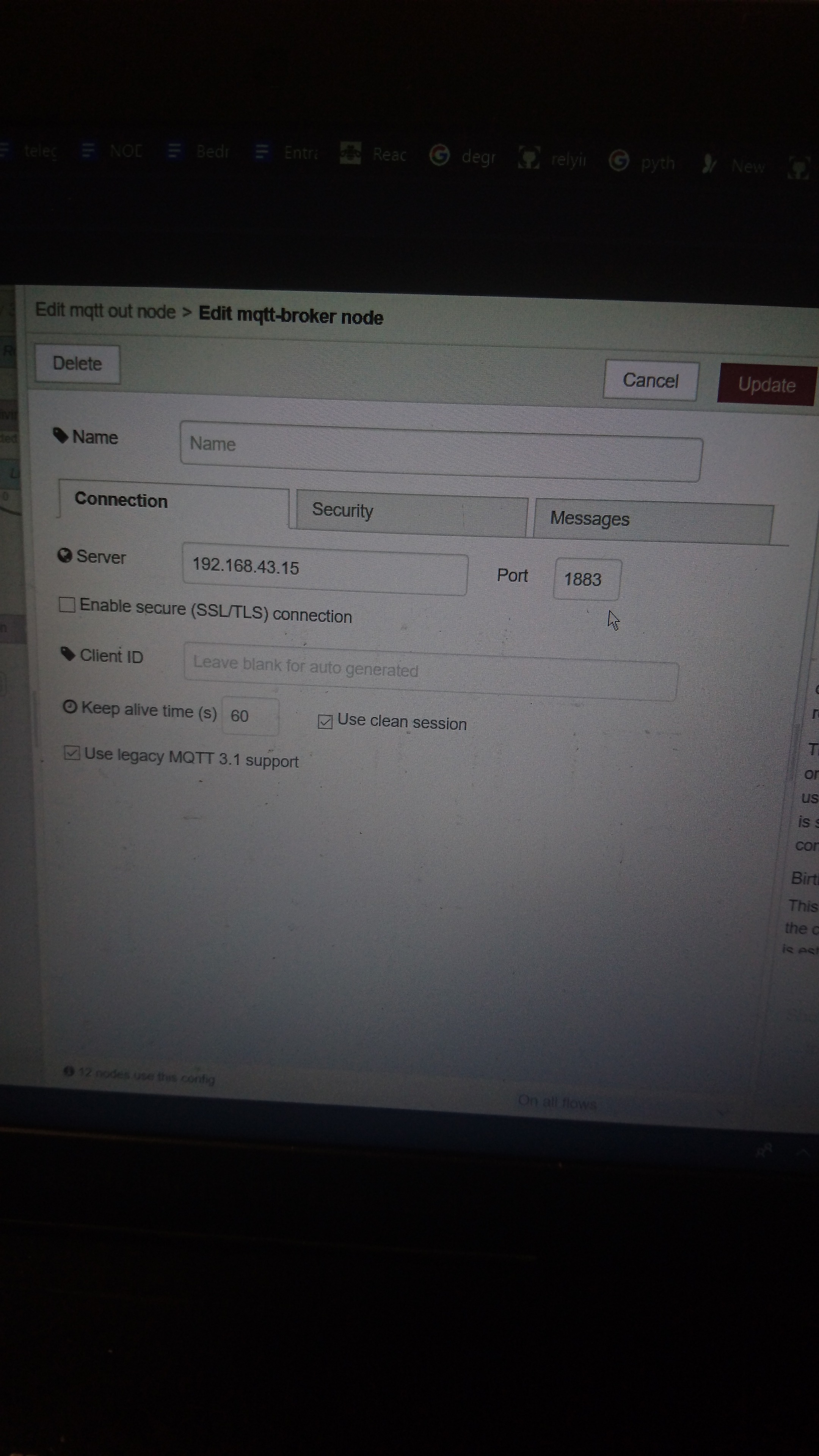
Click on the hamburger menu and go to Import > Clipboard
Paste in the code in the link below and click Import
https://pastebin.com/raw/x4wZJvFk
Click on the pen icon
Enter the IP address of the Bedroom RPi in the Server field
Click on Update. All other MQTT nodes on the same flow will be updated.
Import Flows for Bluemix
Click on the hamburger menu and go to Import > Clipboard
Paste in the code in the link below and click Import
https://pastebin.com/raw/CR3Fsbn2
Deploy the App
Click the Deploy button to deploy the app.
If MQTT fails to connect after deploying, enter the following 2 commands (one at a time) to stop and restart Mosquitto then try again.
sudo /etc/init.d/mosquitto stop
mosquitto
Viewing the Dashboard
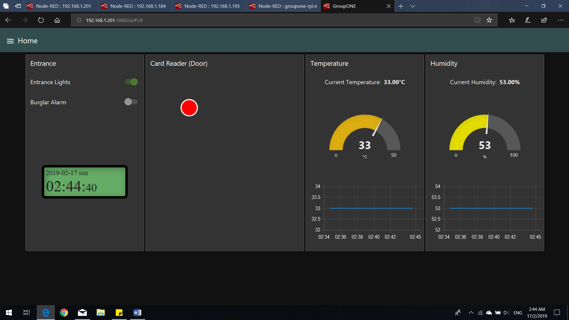
Go to <Insert IP Address of Entrance RPi>:1880/ui (e.g 169.254.43.161:1880/ui)
You should see the screen above.
Viewing the Dashboard #2
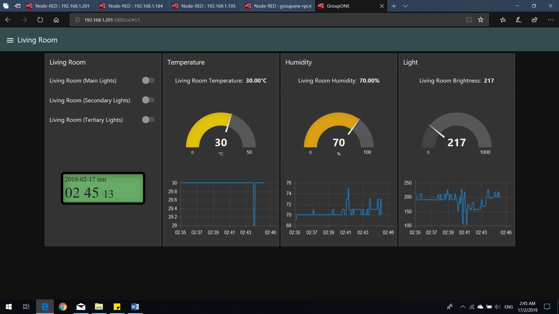
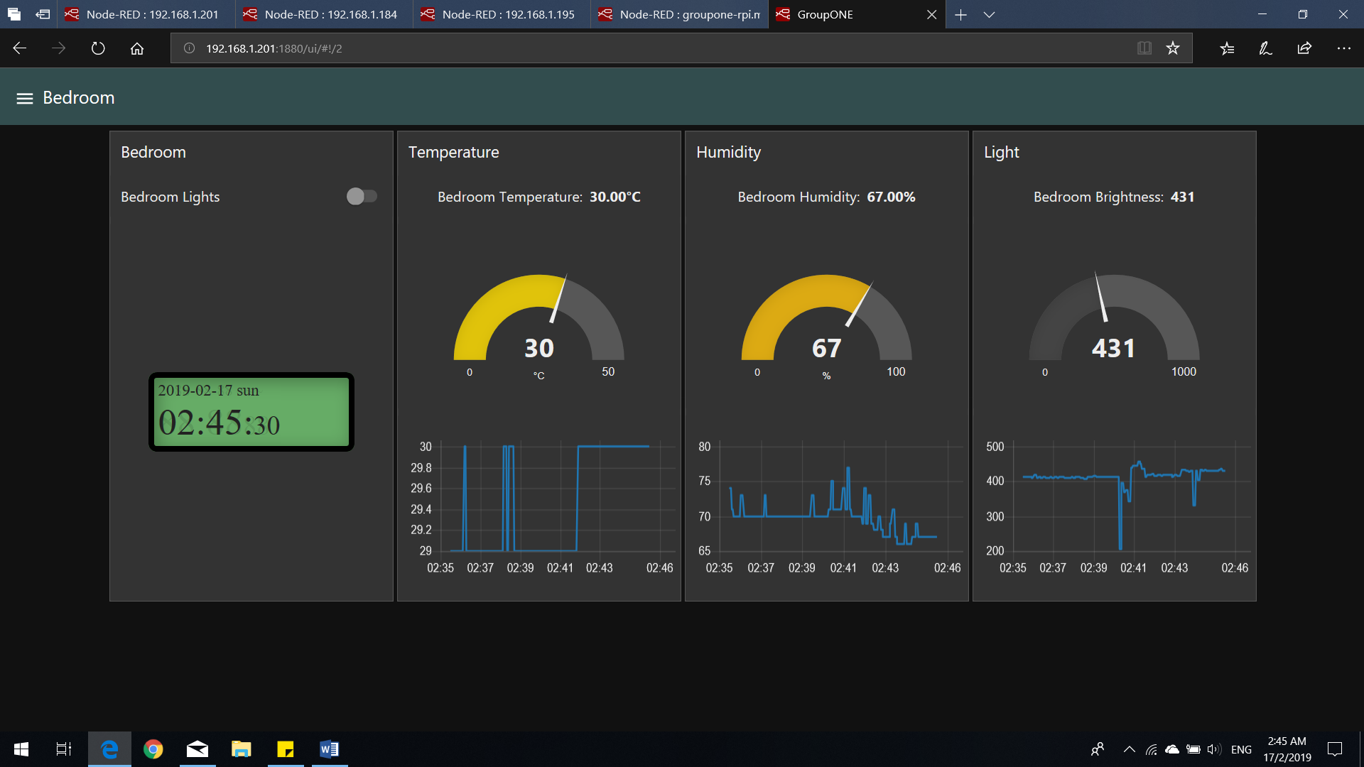
You can access the dashboard for the other 2 RPis (shown above) by clicking on the hamburger menu icon and selecting the RPi you wish to view the dashboard for.
Using the Chatbot
.jpeg)
.jpeg)
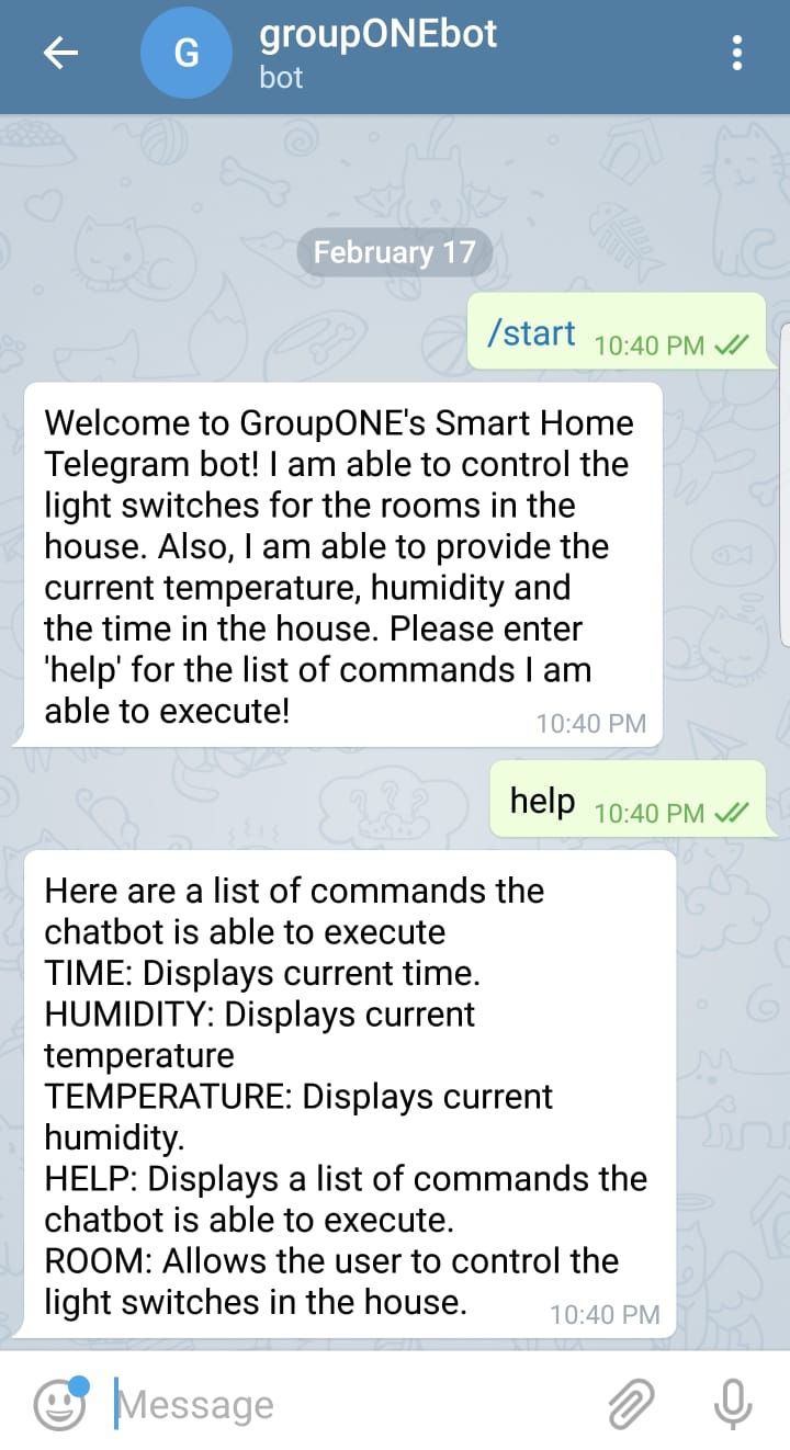
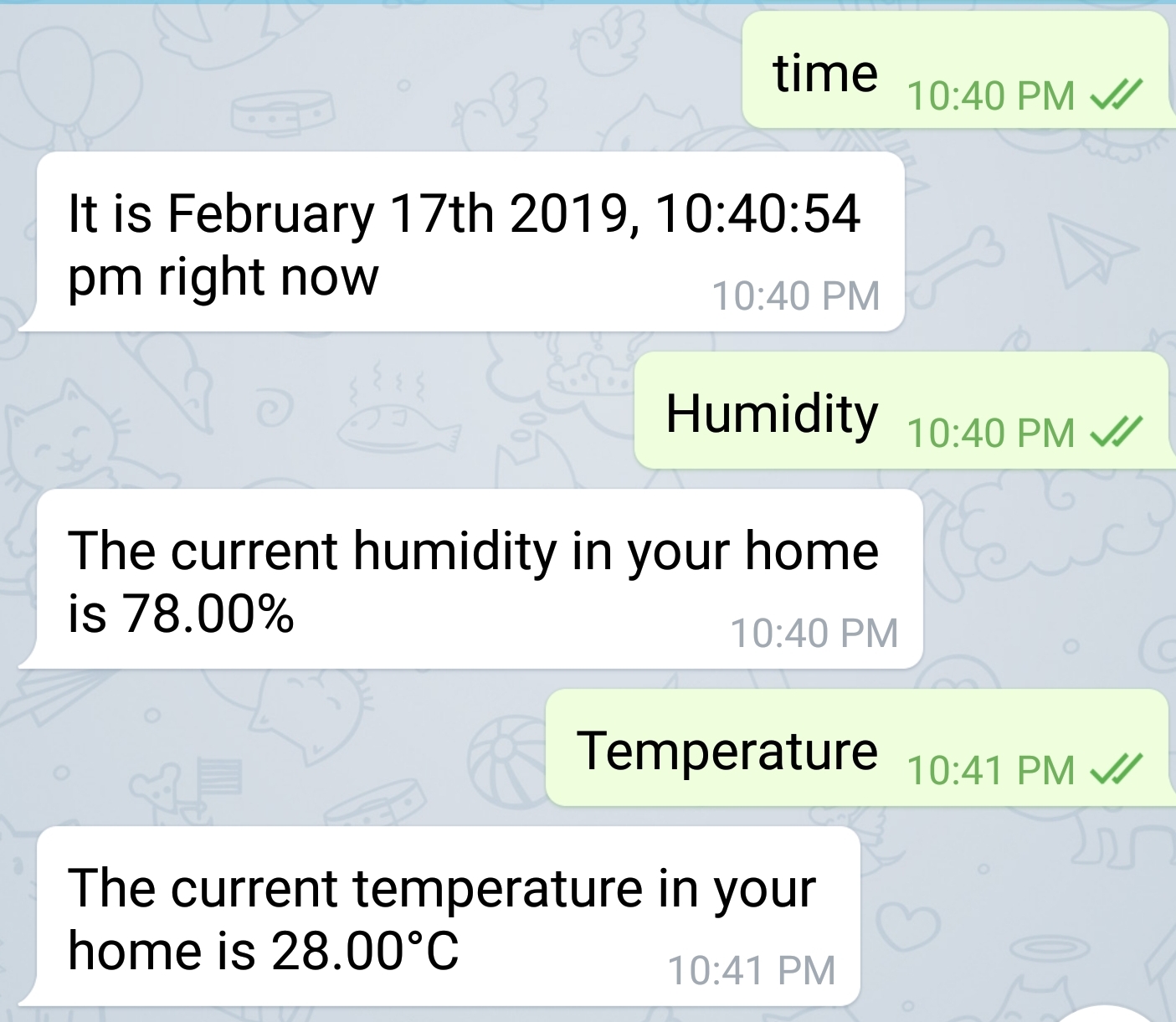
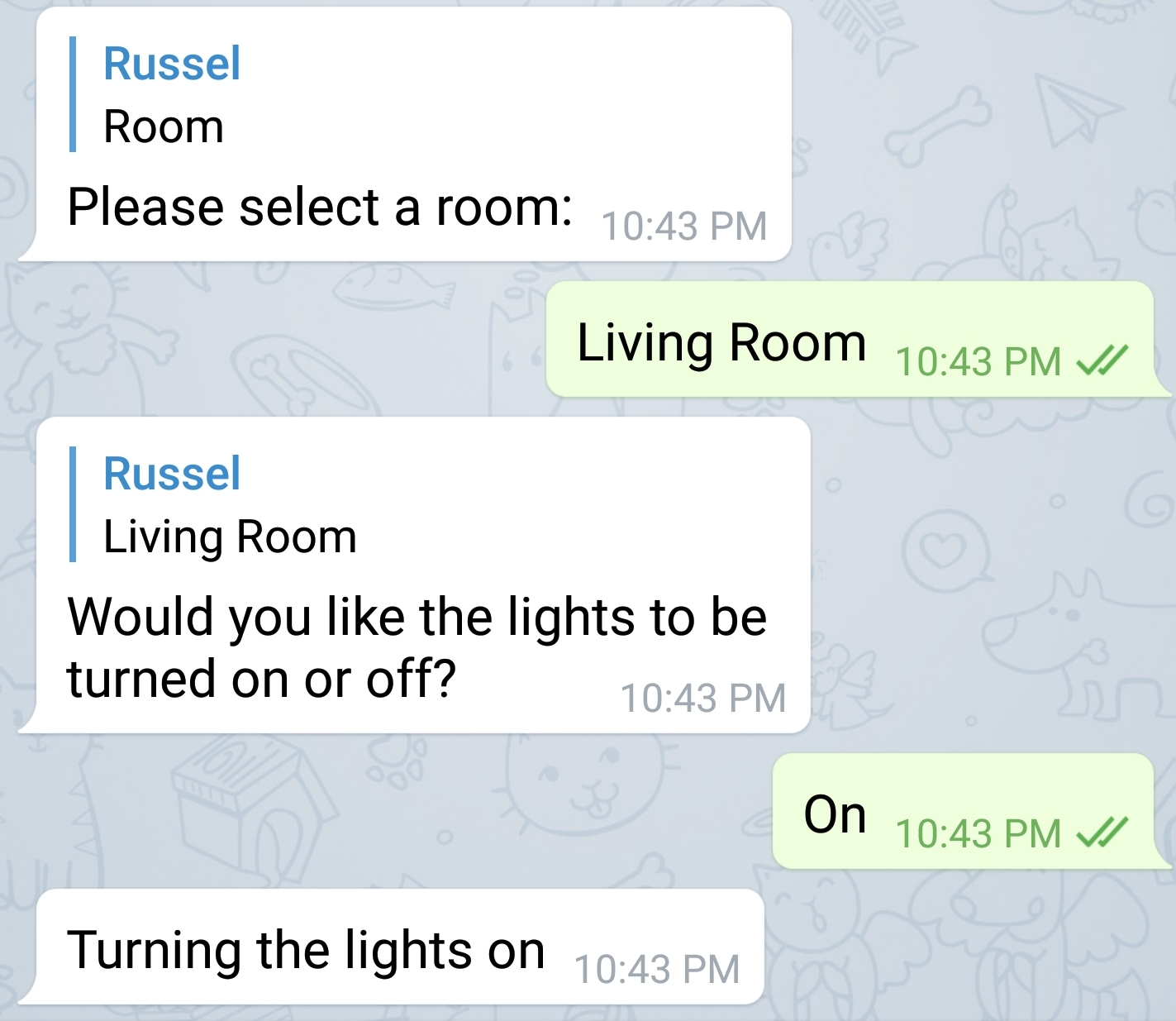
The applicaiton includes a Telegram bot as well. The name of the bot is groupONEbot. A list of commands can be shown using the help command, as seen below. Above are some examples of the possible use cases.