Glowing Spinning Cube
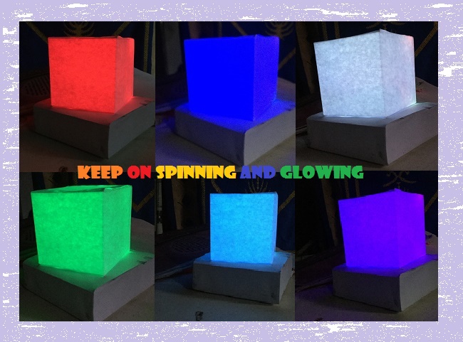
You probably must have attended parties in the past, and part of what makes a party memorial is how dazzling and attracting the environment is. That is why a decided to make this instructables.
Therefore in this instructables, we will learn how to cheaply make a glowing spinning cube. The cube will be made up of electric circuits. Amazingly, you can get as many colors as possible from the glow!
I have made the project as simple as possible so that it can be easily replicable. No much engineering expertise needed. Let’s get started.
Tools and Supplies
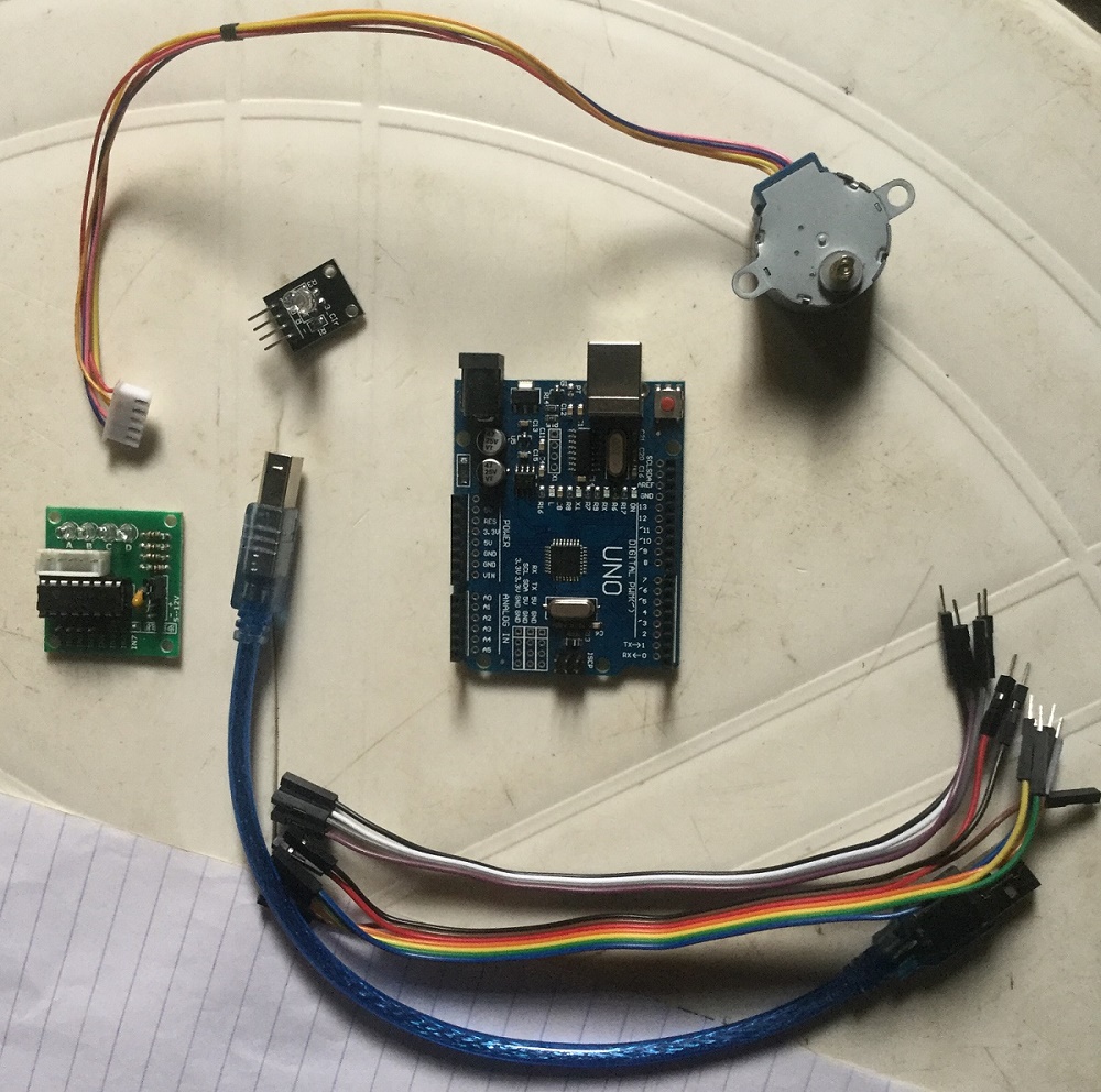
- 1 x Arduino UNO.
- 1 x RGB Module.
- 1 x Stepper motor and ULN2003 Driver.
- Male to female Dupont wires.
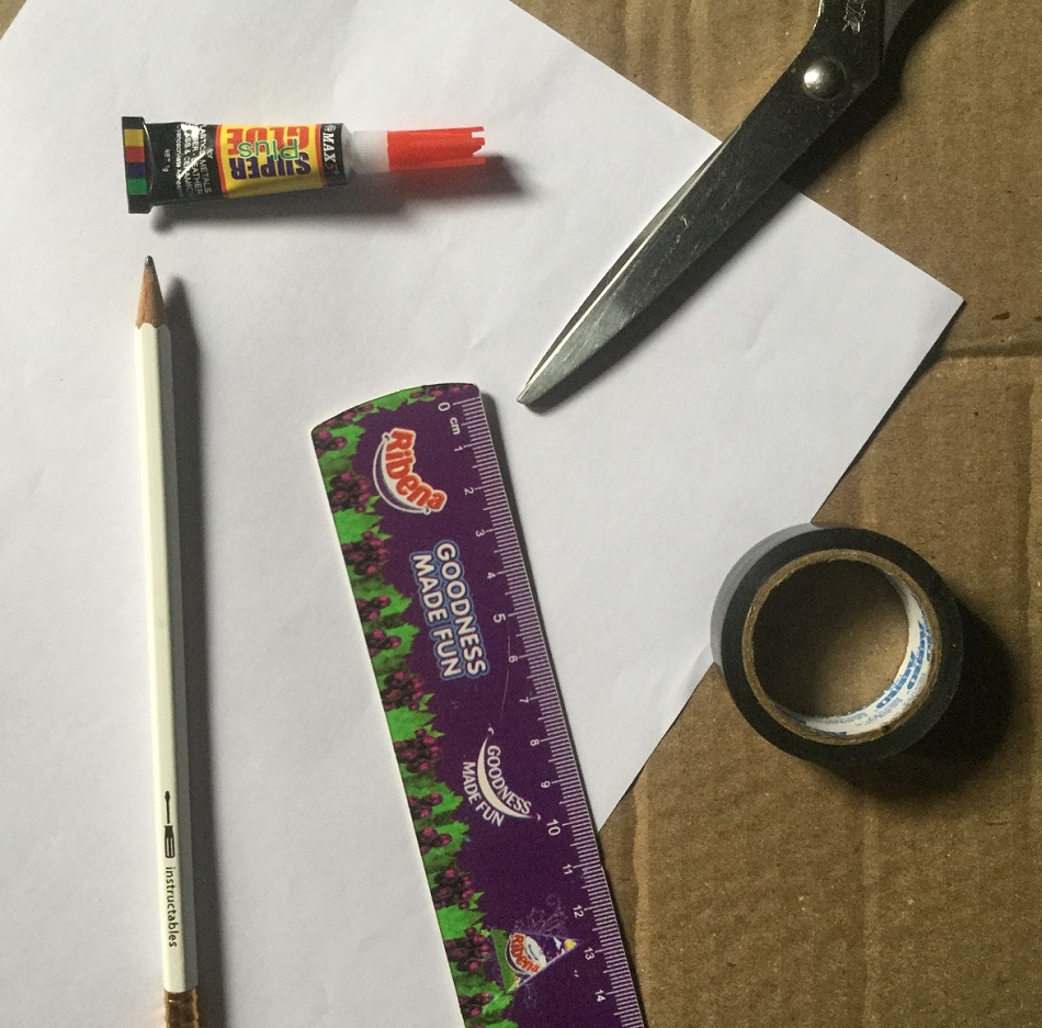
- Cardboard.
- Scissors.
- Plain A4 Papers.
- Pencil.
- Ruler.
- Razor Blade (optional).
- Paper gum.
- Super Glue.
- Tape.
- 9V Battery with snap.
Cut the Cube
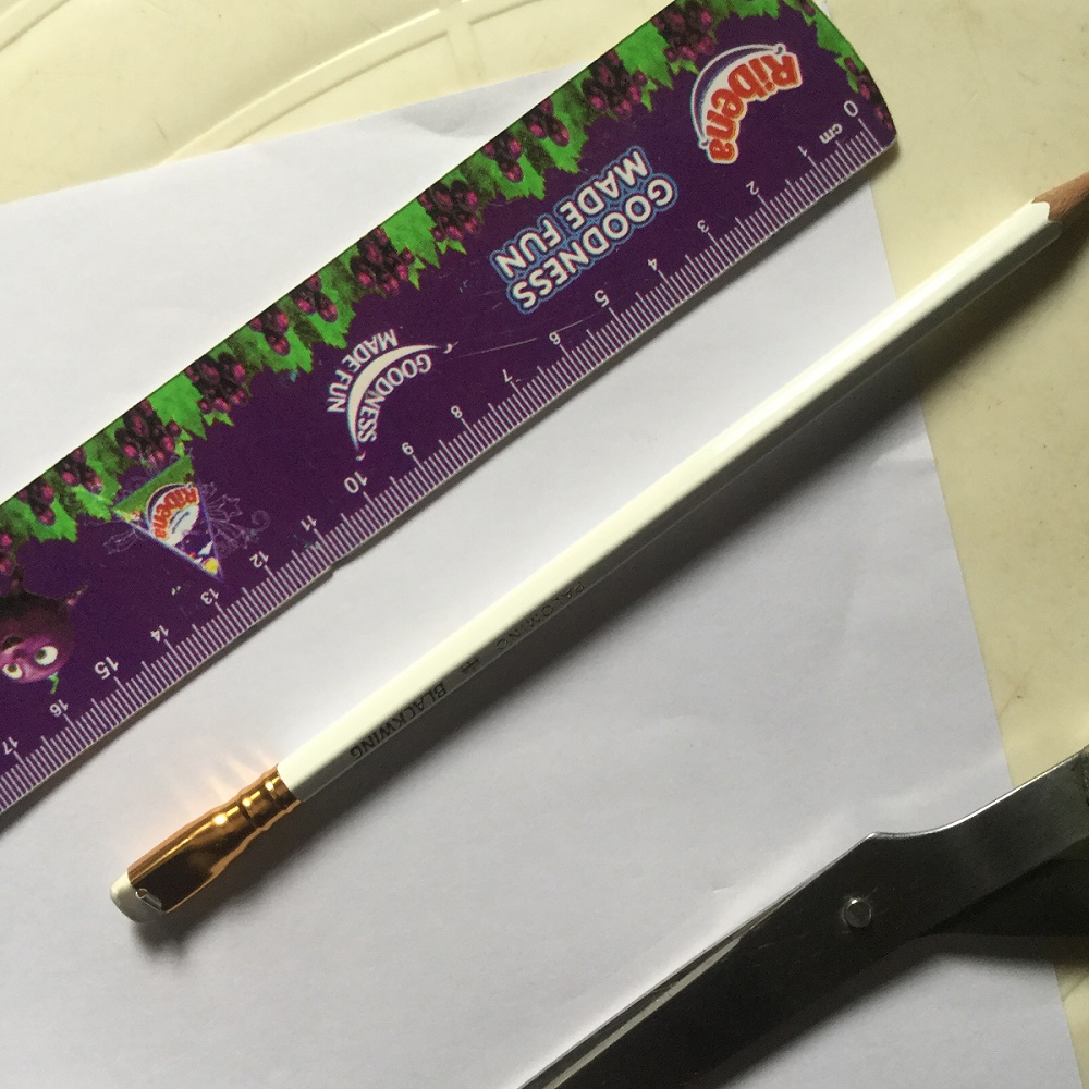
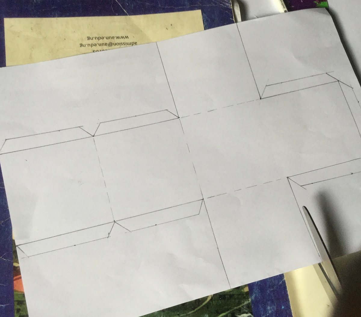
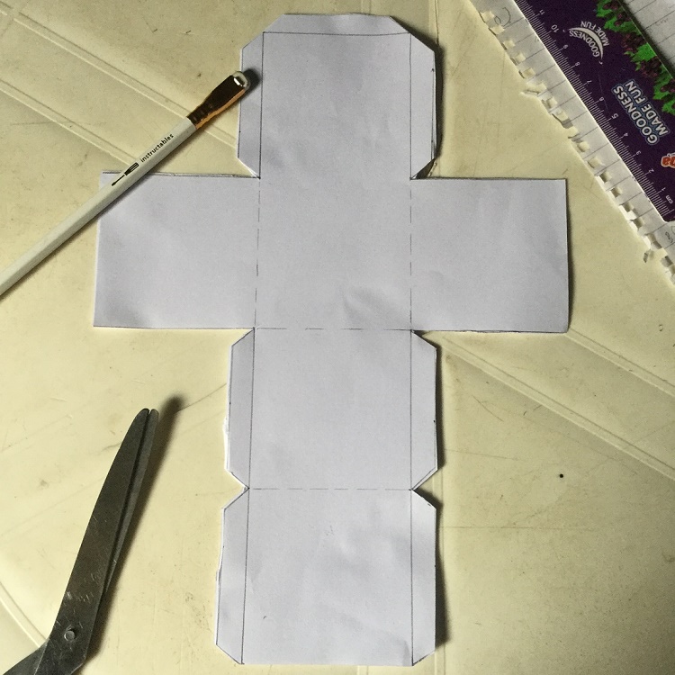
As seen in the images, the cube is of dimension 7cm x 7cm x 7cm, with a clearance of 1cm at some edges. The clearance will make the surfaces bind easily.
So pick up the plain paper, use your ruler and pencil to mark out the dimensions of the cube on the paper, then use the scissors to cut out the marked out area. By now you should have get the pattern to be used for the cube. The cube is going to be double layers i.e. we will be using two cubes, therefore take another plain sheet of paper and use the gotten pattern to cut out the second pattern.
Cut the Base Cuboid
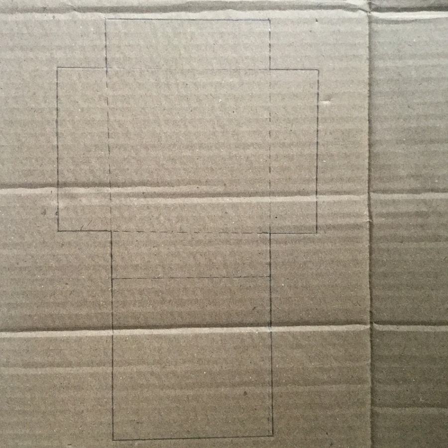
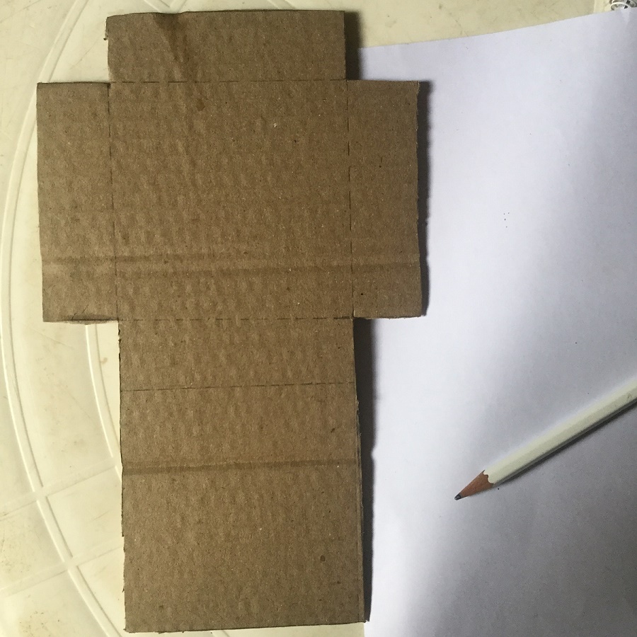
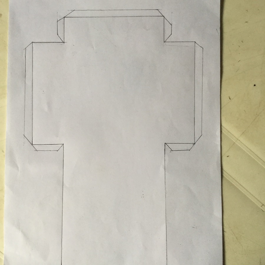
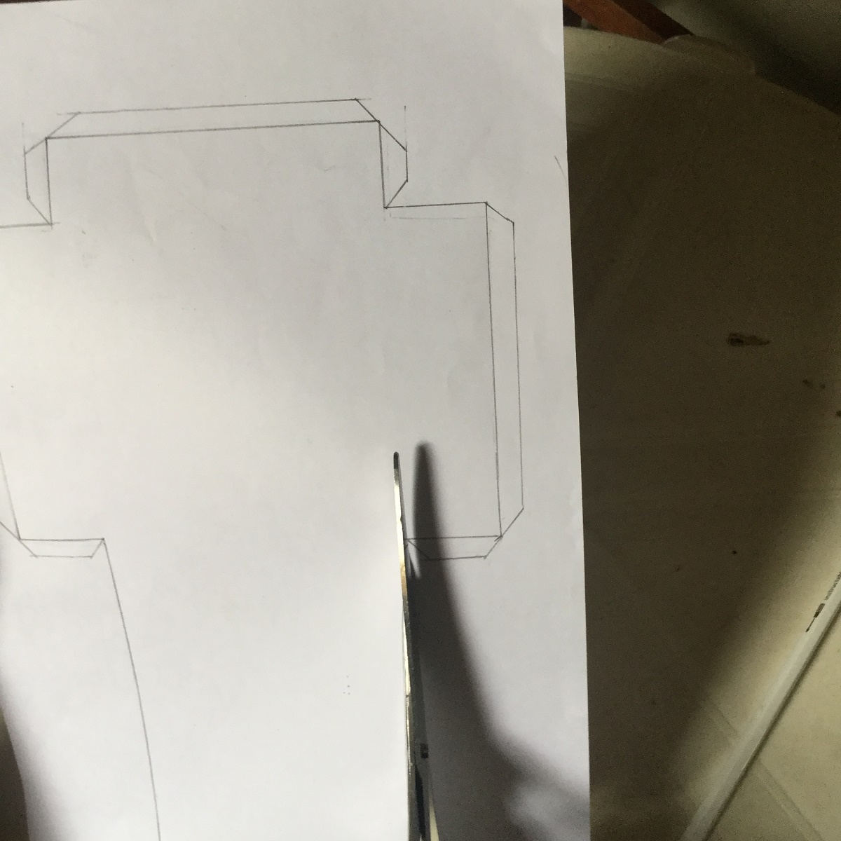
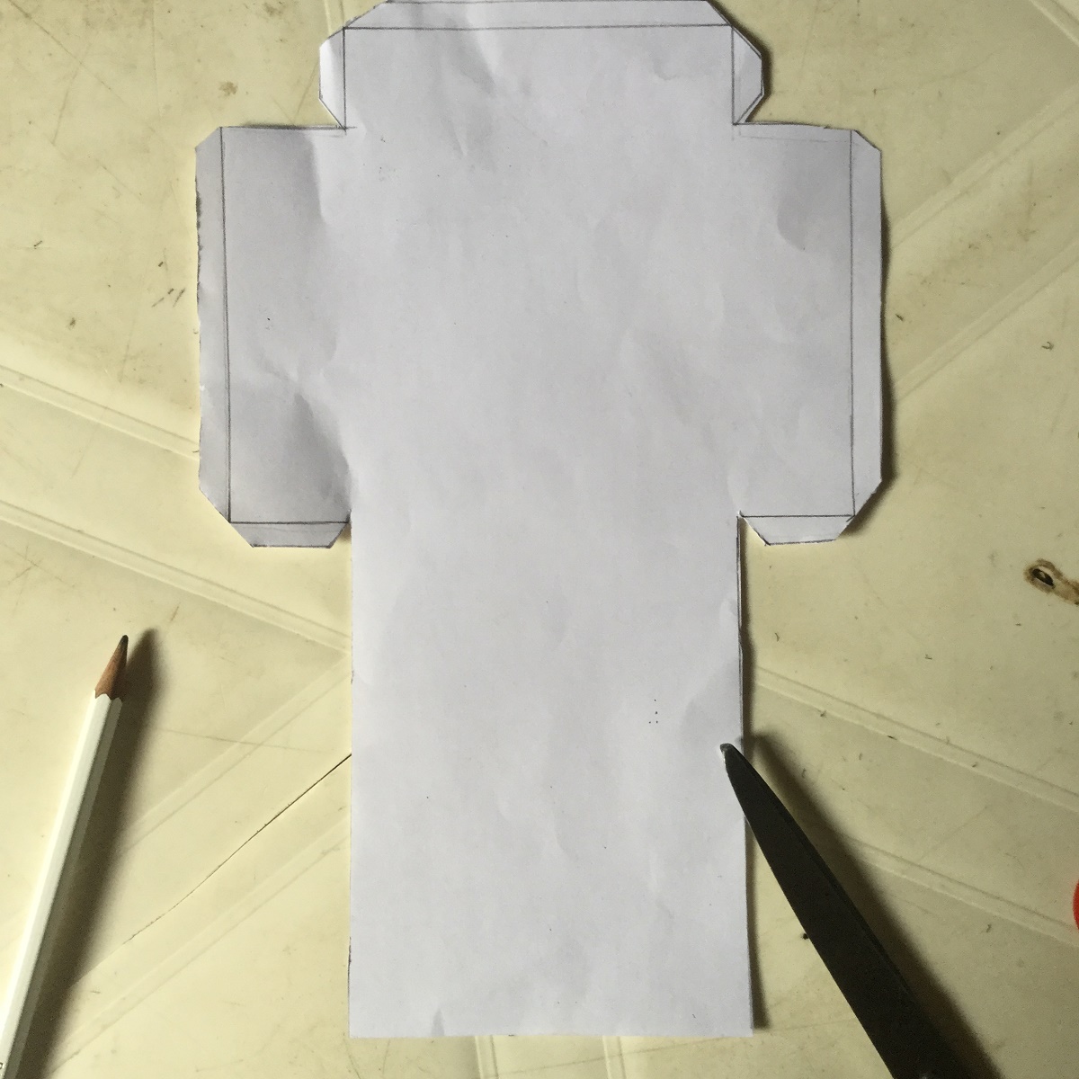
Next is to cut out the cuboid, so pick up your cardboard and use your ruler and pencil to mark out the dimensions. As shown in the image above, it is of dimension 10cm x 10cm x 4cm, with also some clearance at some edges.
After marking out, use the scissors to cut out the pattern. The cardboard will be wrapped with plain paper. So take a plain sheet and using you ruler, pencil and scissors, mark and cut out another pattern is of dimension 10cm x 10cm x 4cm, with also some 1cm clearance at some edges as seen in the above images.
This cuboid will serve as a base for the cube and will contain the electric circuit.
Fold and Glue the Patterns
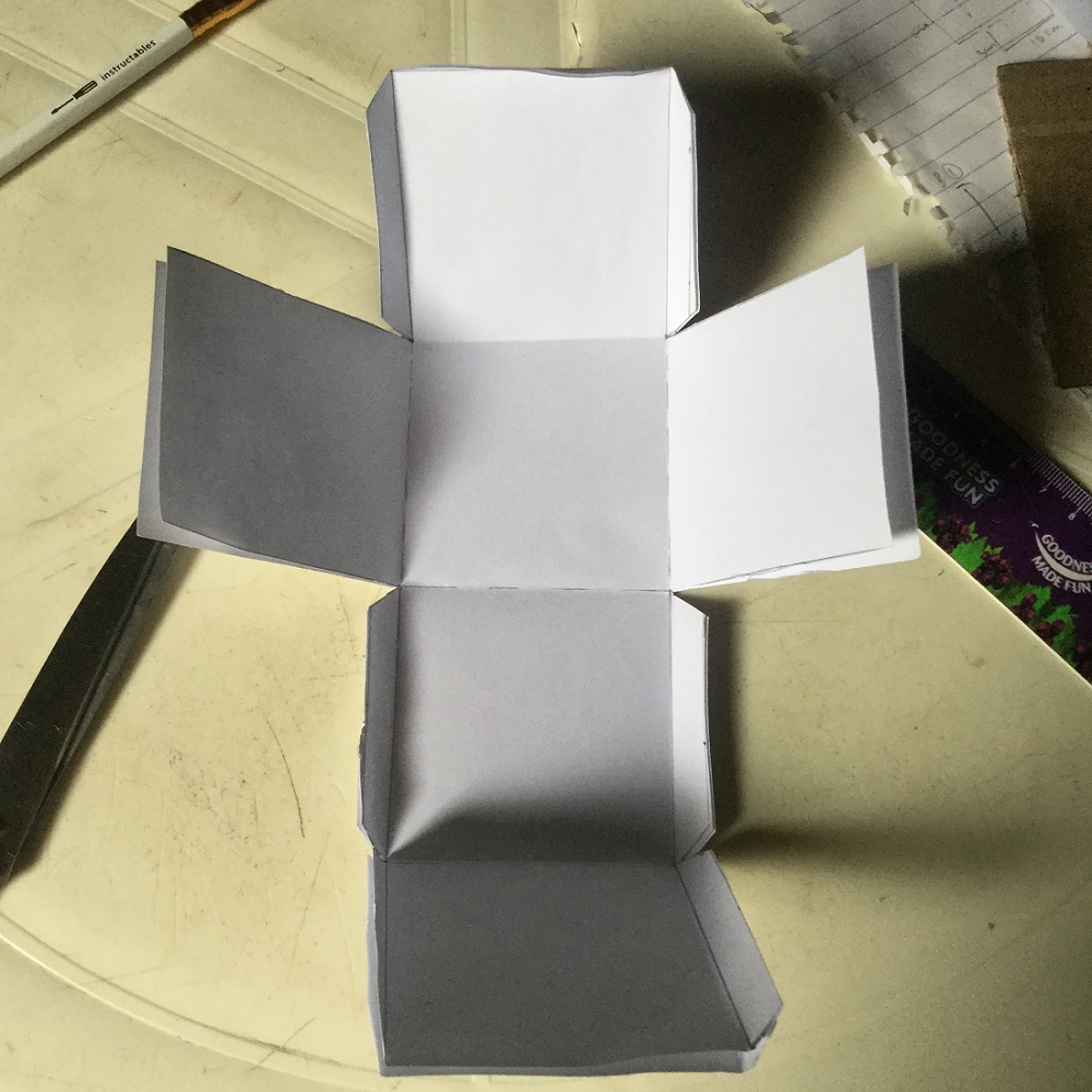
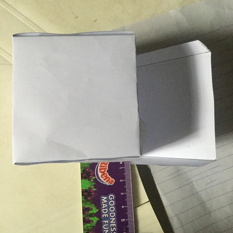
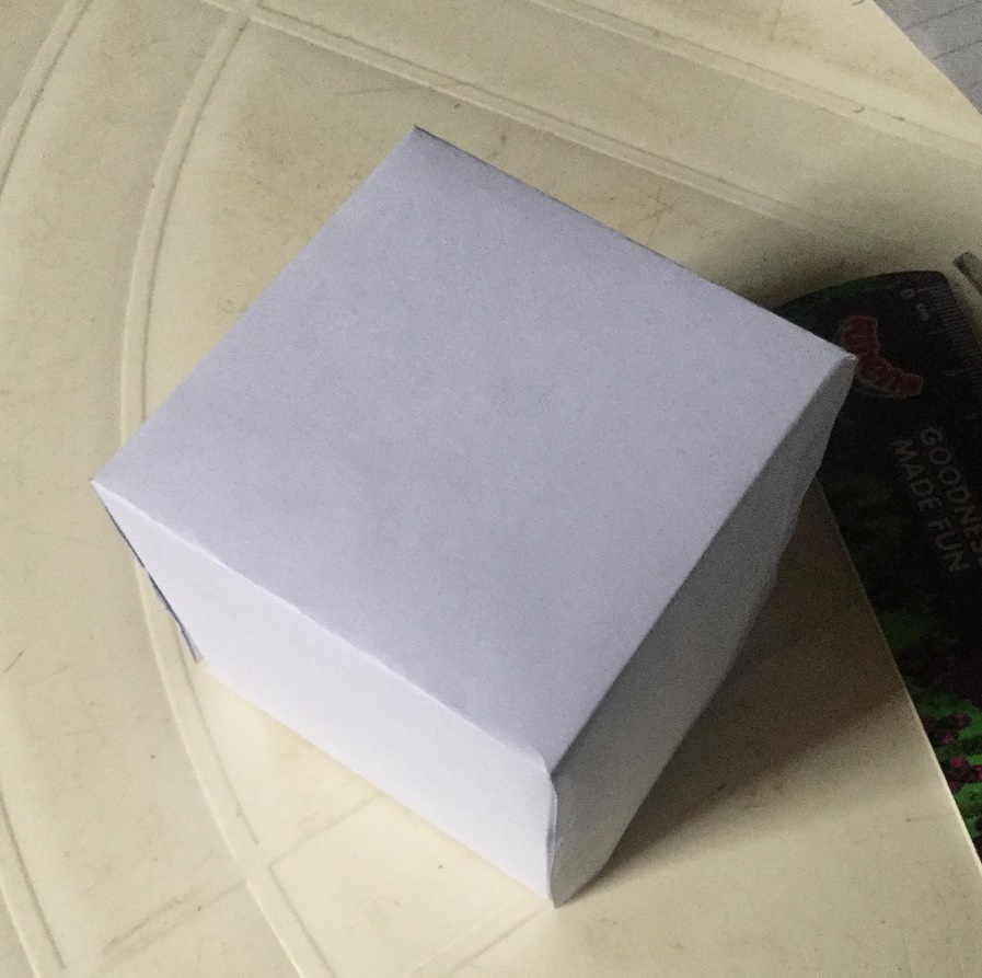
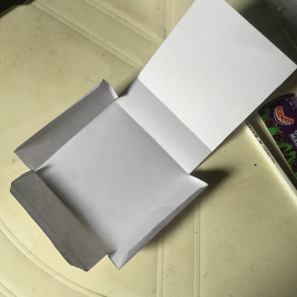
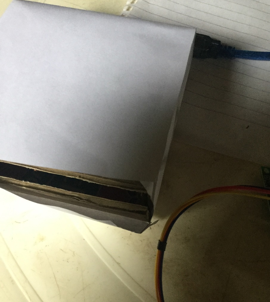
Fold the patterns to form the required shapes.
Then glue all edges except the ones for a face where the circuit will be inserted through. So at the end, you should have something like an open box.
Setup the Circuit
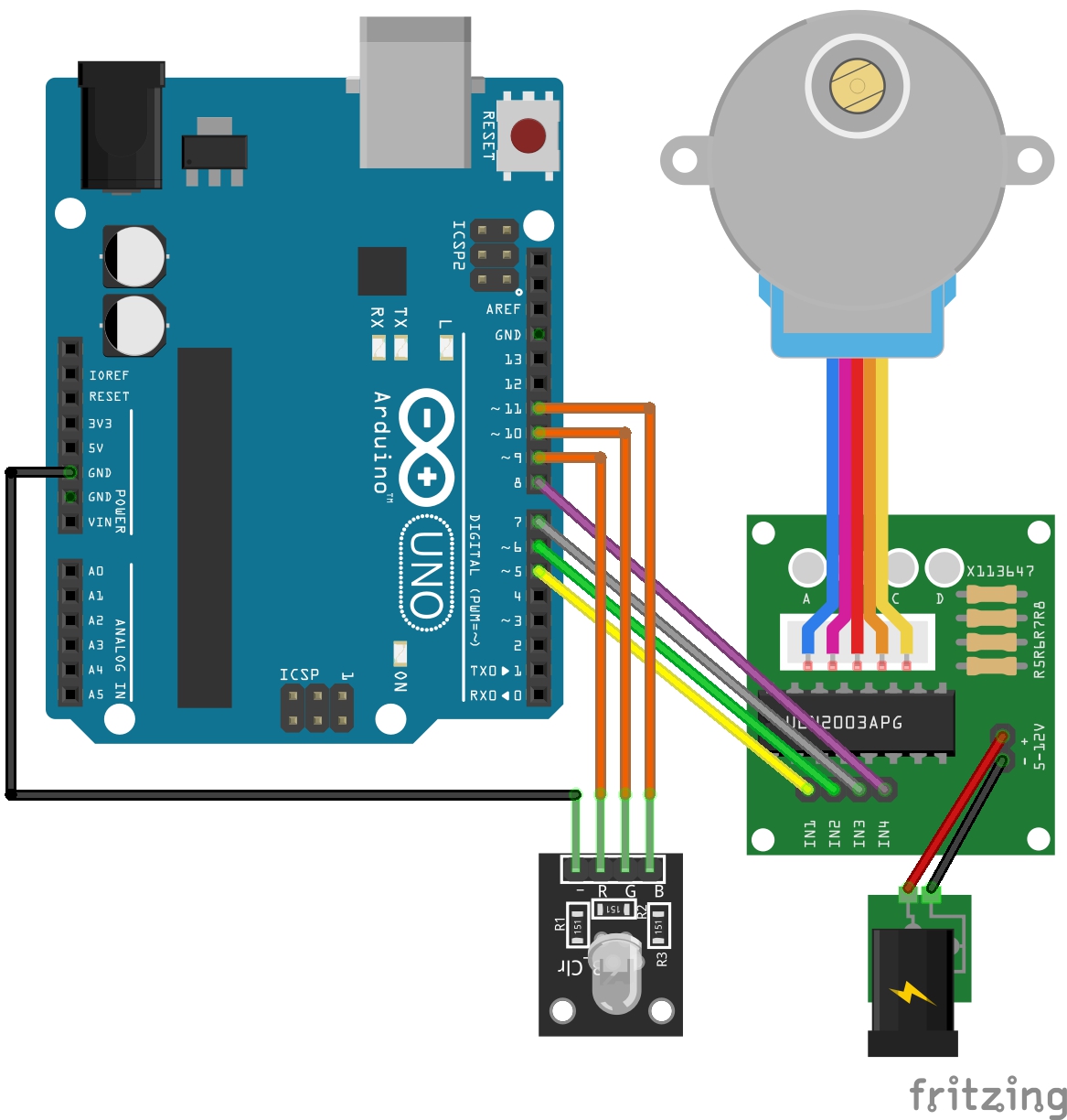
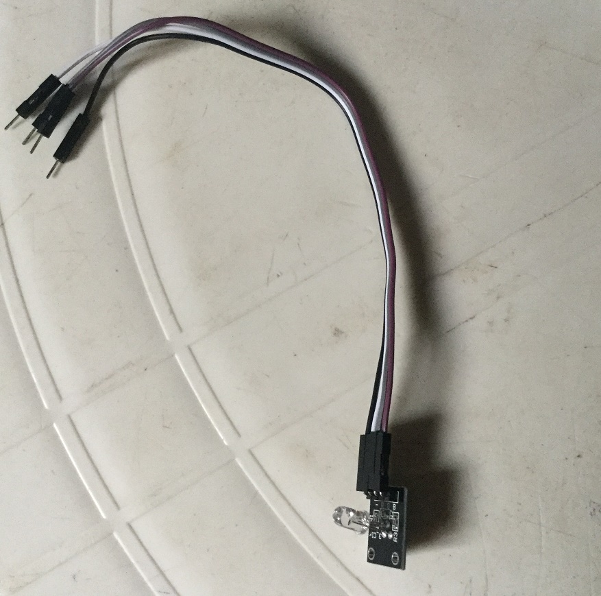
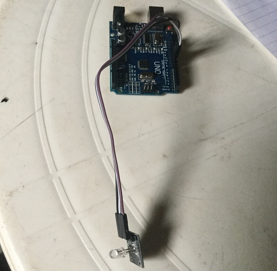
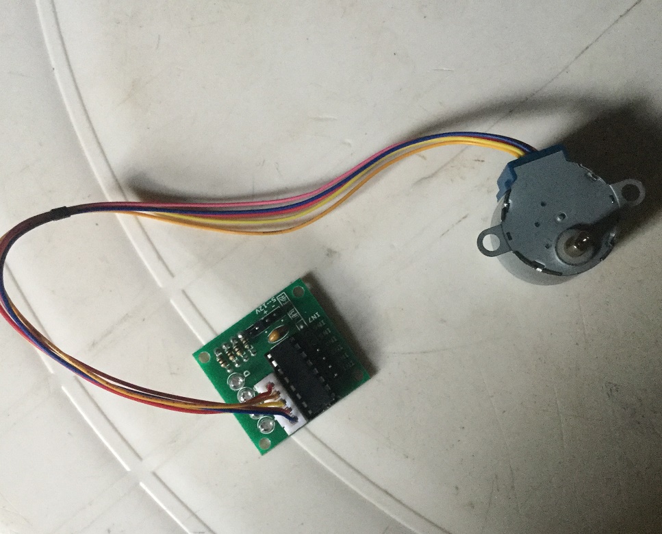
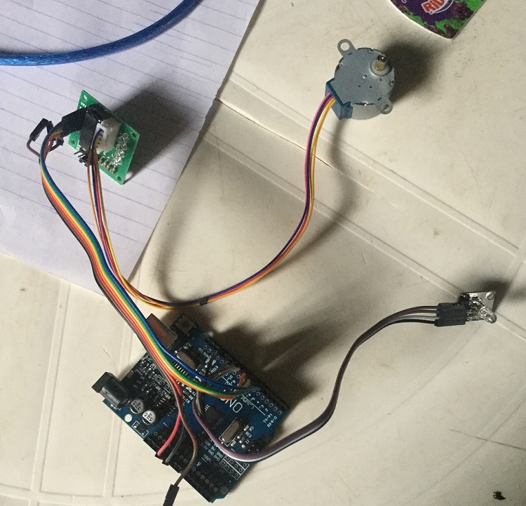
All components should be connected as in the image above so that it will work as expected. Incorrect connection might render the circuit to be incompatible with the code.
Upload the Code
The code controlling the complete system is giving below, though I have attached the ino file above, and I have included all needed details by commenting the code. So, you can have a look at the code.
The next thing is to connect your Arduino using the type A-B USB cable. From the Arduino IDE, upload the code to the board, make sure you select the correct port.
It is advisable to test the code with the circuit before the final assembly.
#include //Include stepper library
//RGB Module connection
#define RED_PIN 9
#define GREEN_PIN 10
#define BLUE_PIN 11//stepper driver connection for motor control
#define IN1 5
#define IN2 6
#define IN3 7
#define IN4 8const int stepsPerRevolution = 200; // number of steps per revolution
// initialize the stepper library on pins 5 through 8
Stepper myStepper(stepsPerRevolution, 5, 6, 7, 8);void setup() {
//set the RGB module & stepper driver as output pins
for(int i= IN1; i <= BLUE_PIN; i++)
{
pinMode(i, OUTPUT);
}// set the speed for cube spinning
myStepper.setSpeed(60);
}void loop() {
// the spinning in steps
//independently set each color to from low to high and vice versa
for(int color_pin = RED_PIN; color_pin <= BLUE_PIN; color_pin++)
{
for(int i = 0; i < 255; i++)
{
analogWrite(color_pin, i);
delay(20);
}
for(int i = 255; i > 0; i--)
{
analogWrite(color_pin, i);
delay(20);
}
}//gradually set colour to high
for(int color_pin = RED_PIN; color_pin <= BLUE_PIN; color_pin++)
{
for(int i = 0; i < 255; i++)
{
analogWrite(color_pin, i);
delay(20);
}
}//randomly generate colors
for(int i = 0; i < 20; i++)
{
for(int color_pin = RED_PIN; color_pin <= BLUE_PIN; color_pin++)
{
analogWrite(color_pin, random(1, 255));
delay(500);
}
}
//Turn all the colors off
for(int color_pin = RED_PIN; color_pin <= BLUE_PIN; color_pin++)
{
digitalWrite(color_pin, LOW);
}myStepper.step(20000);
}
Downloads
Assemble the System
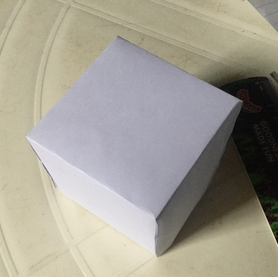
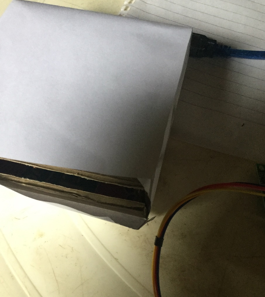
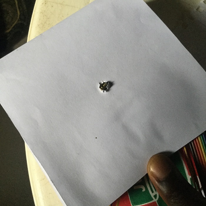
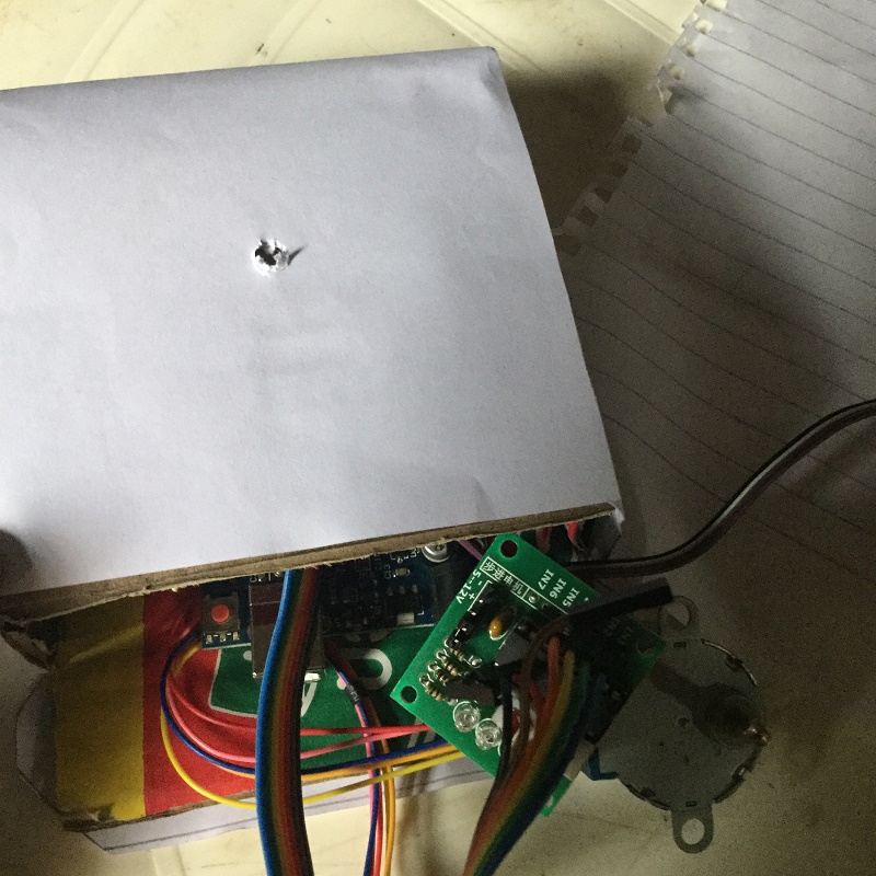
Once you have uploaded the code and connected the circuit accordingly, then you can bring everything together.
The cuboid will serve as a base containing the Arduino and stepper motor while the cube will be mounted above it. The cube will embed the RGB LED. Take the cube and drill a small hole in its base to enable the RGB LED enter into it. The hole should be some distance away from the center. To attach the cube to the stepper motor, you should first attach a shaft to the motor then attach the cube’s base to the shaft, this implies that you have to cut a small circle on the top of the base cuboid. Alternatively, you can just directly attach the cube to the stepper motor. To power the system, you can use the USB cable for the Arduino. You can also supply the ULN2003 module power from the Arduino, but it is advisable to have another different power source for that. You can also power the Arduino with a 9V battery if there is no available USB port.
After everything is in place, you can now glue the open sides of the boxes.
Enjoy!
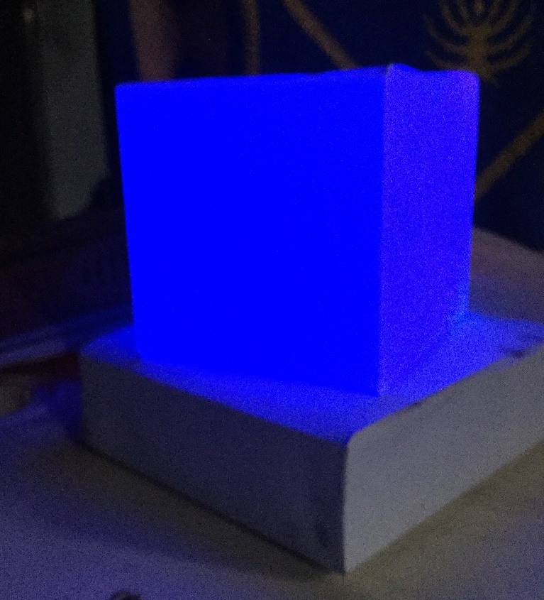
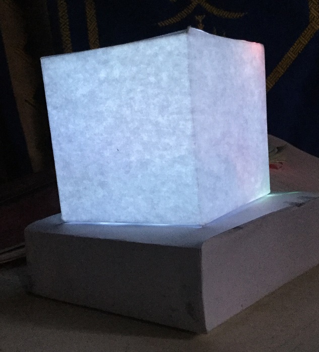
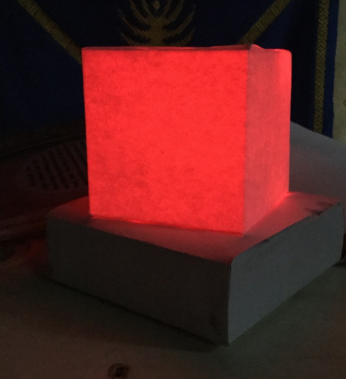
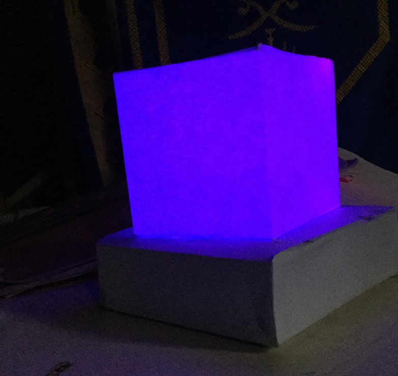
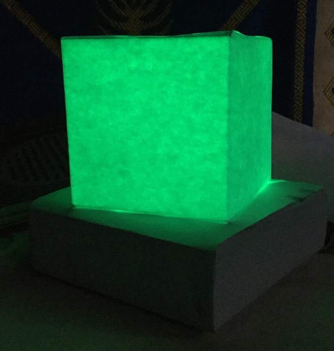
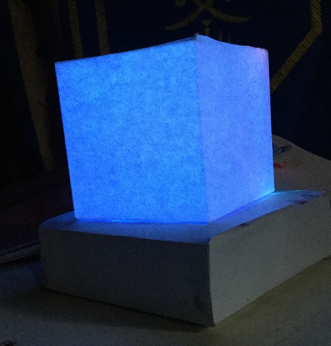
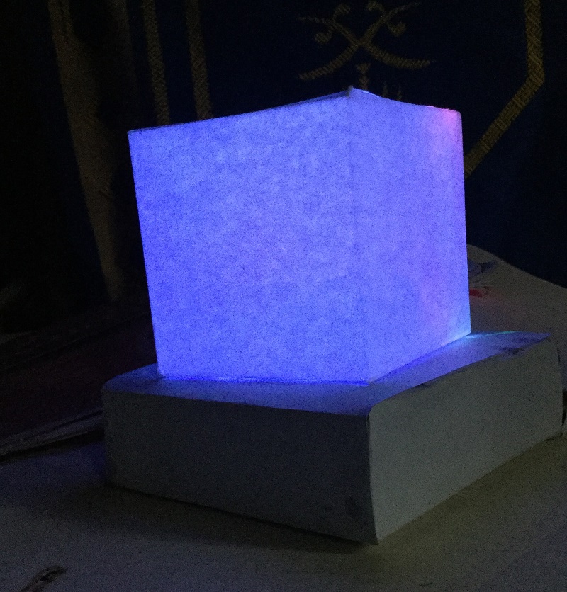
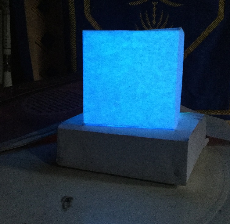
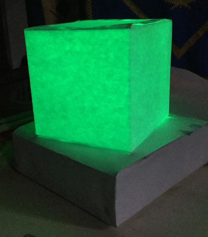
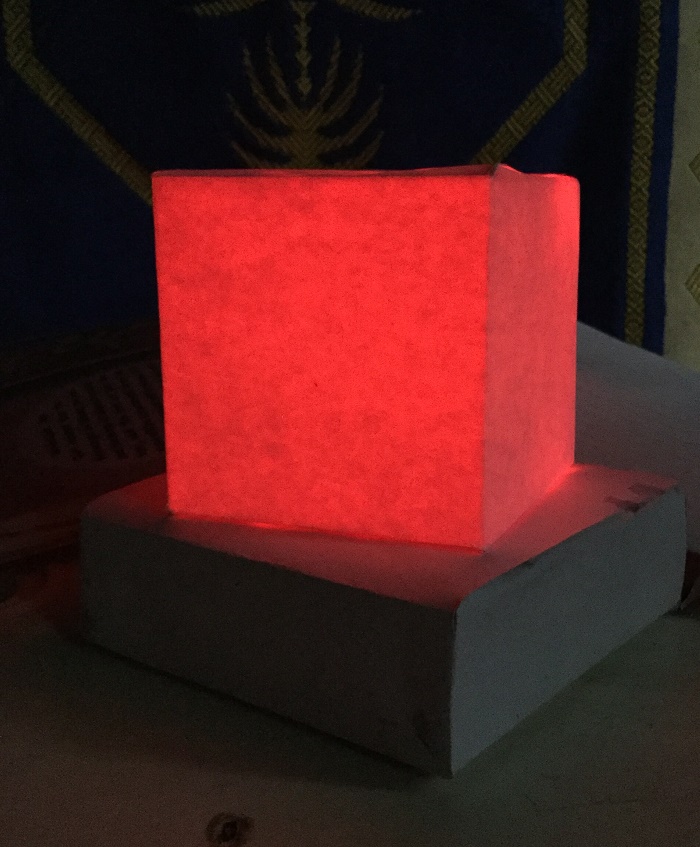
Once the system is assembled, the only thing left is to enjoy.
You will now experience the glow in gazillion of colors.
Have fun!