Getting Started With a Temperature Sensor
by JayconSystems in Circuits > Sensors
13354 Views, 121 Favorites, 0 Comments
Getting Started With a Temperature Sensor
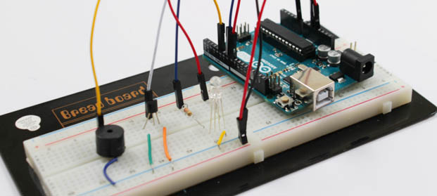
Using basic electronic sensors, we can build our own heat detector. The main component, which is the LM35DZ temperature sensor, is used to measure the current room temperature. Based on the measurement, the detector will warn the user using other sensors such as the buzzer and the LED to indicate whether the room temperature exceeds the limit. This tutorial explains what kind of equipment we are using, how to program, and what to expect from it.
Hardware
If you would like to follow along with this tutorial, then you will need the following materials:
Hardware Assembly - Connecting Wires
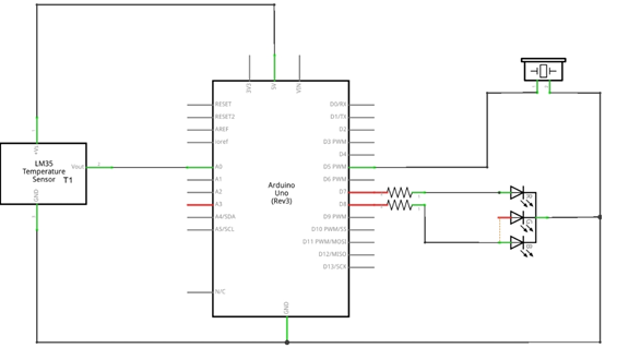
Place a black and red wire on the breadboard. Connect the red wire to 5V on the Arduino while the black wire is connected to the GND.
Hardware Assembly - Connecting the RGB LED
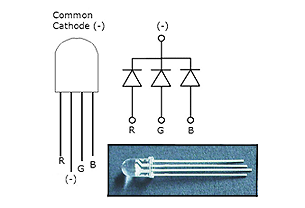
Place the RGB LED on the breadboard and connect the longer pin of the RGB to the GND of the Arduino. The right most pin (next to the longer pin) of the RGB LED should be connected to digital pin 8 on the Arduino while the left most pin should connect to the digital pin 7 on the Arduino. Note that LEDs act like a diodes, which means they are direction sensitive and don’t have internal resistance. Always use small resistors to prevent them from burring the metal.
Hardware Assembly - Placing the Temperature Sensor
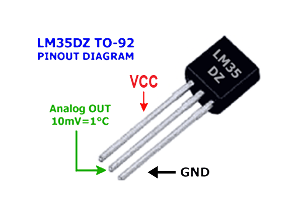
Place the LM35DZ Temperature Sensor on the breadboard. Then you are ready to connect the right most pin to the ground, the center pin to the analog pin A0 on the Arduino, and the left pin to the power supply (5V of the Arduino).
Hardware Assembly - Adding the Buzzer
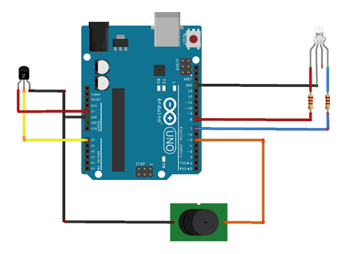
Place the buzzer on the breadboard. Connect the positive pin to the PWM (Pulse Width Modulation) pin 5 on the Arduino and the negative pin to the GND on the Arduino.
Software Code & Explanation
// Declaring global variable <br> int R_LED = 8; // assigning the Red LED of the RGB to be connected at pin 8
 int B_LED = 7;// assigning
 int Buz= 5 ;
 const int temp = 0; // assigning the temperature sensor pin connection
void setup()
{
 Serial.begin (9600);// opening serial comminication between the computer and Arduino
 pinMode (R_LED, OUTPUT); // declaring the LED as an output
 pinMode (B_LED, OUTPUT);
 pinMode (Buz, OUTPUT);
 pinMode (temp, INPUT); } void loop()
{
 float Real_Voltage = analogRead(temp)* 0.004882814; // reading the sensor value and convert it to voltage
 float Temp_C = Real_Voltage * 100.0;// changing the voltage into Celsius
 float Temp_F = Temp_C * (9.0/5.0) + 32.0;
 // printing the value of the serial monitor
 //Serial.println(analogRead(temp));
 Serial.print("Voltage: ");
 Serial.println(Real_Voltage);
 Serial.print("Deg C: ");
 Serial.println(Temp_C);
 Serial.print("Deg F: ");
 Serial.println(Temp_F);
 // check if the sensor is above the maximum limit
 if ( Temp_C >= 26.0)
 {
   Serial.println("Warning: The system is hot");
   digitalWrite(R_LED, HIGH); // Red LED on
   analogWrite(Buz,20);
   delay(2000);// wait for one sec
   digitalWrite(R_LED, LOW);// Red LED off
   analogWrite(Buz,0);
   delay(2000); // wait for one sec
 }
 // check if the sensor is above the mimimum limit
 else if (Temp_C <= 25.0)
 {
   Serial.println("Warning: The system is cold");
   digitalWrite(B_LED, HIGH);// Blue LED on
   analogWrite(Buz,80);
   delay(2000);
   digitalWrite(B_LED, LOW);
   analogWrite(Buz,0);
   delay(2000); // wait for a sec
 }
 else
 {
   Serial.println("The system is functioning well ");
   digitalWrite(R_LED, LOW);
   digitalWrite(B_LED, LOW);
   delay(2000);
 }
}
The first part of the code defines the global variable pin that is used by the RGB LED, temperature sensor, and the buzzer. This pin can be used by any function declared in this program. The RGB is connected to a digital pin while the others to an analog pin on the Arduino.
Inside the setup function we have opened a serial communication between the computer and the Arduino using specific frequency band, which in this case is 9600. Then we defined which pin is used as an output or input. Question for you: what happens if you don’t declare temperature sensor pin and RGB pin as an input and output pin respectively? Why do you think that is?
When we look at the loop function, most of the main code resides in here. The first thing we did is read the value from the temperature sensor and converts it into voltage. The function analogRead() return is an integer value between 0 to 1023 since Arduino board contains 10 bit analog to digital converter (2^10 = 1024). In order to map this 10 bit character read by the temperature sensor into analog value, we need to multiply the sensor value with the resolution of the Arduino board, which is approximately 0.0049( 5V/1024 units ). After getting the voltage value, it needs to be converted into degree Celsius using the scale factor 0.01V/0C of LM35DZ temperature sensor.
Check Our Work!
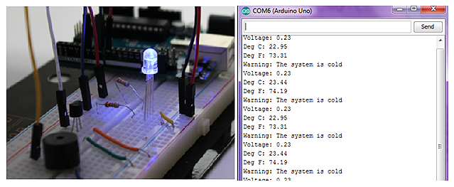
Then we check using a control structure like the “if statement” function to check whether it reached the maximum temperature (hot) or minimum temperature (cold). If it does, it will give out a warning using the LED and the buzzer as well as display the warning on the serial monitor.
If the detector doesn’t work after running the code, check the connection as well as any mistyping when writing the code. As we conclude this tutorial, we can now use this project to detect our surrounding or any other things you planned it to monitor. You should be able to see the blue LED on the RGB blink when the temperature reads below 25 °C. Also, the red LED on the RGB should blink when the temperature is above 26 °C.
If you have any questions about this tutorial, don't hesitate to post a comment, shoot us an email, or post it in our forum!
Need materials to get started? Check out Jaycon Systems online store!