Getting Started With Tasmota and Introduction to Tasmota Templates
by Pius in Circuits > Microcontrollers
5092 Views, 8 Favorites, 0 Comments
Getting Started With Tasmota and Introduction to Tasmota Templates

What is Tasmota?
Tasmota is an open-source firmware created by Theo Arends for smart home devices using the ESP wifi chip. Tasmota is very common and is compatible with various smart home platforms such as TUYA, Google Home, Home assistant etc. In the course of this article, you will be introduced to Tasmota and its most basic functionality templates and how to create your own template.
Supplies
- Node MCU ESP8266
Installing Tasmota to Your ESP WiFi Chip
For this article, I will be using the node MCU ESP8266 chip. First, we will have to download the firmware. Here are the links to download the Tasmota firmware.
To download the .bin file directly from Tasmota click here
There are several ways to install Tasmota to your esp board but my favourite way is to use esptool, to use esptool you need python installed on your computer. After installing python open your computer terminal and type in
pip3 install esptool
After the installation type in the following command in the terminal,
esptool.py --port [com port] erase_flash
this is to erase the flash memory.
esptool.py --port [com port] write_flash -fs 4MB -fm dout 0x0 [location of .bin file]
replace the part labelled com port with the com port your board is connected to and the part location of .bin file to the location of the .bin file.
Yours should look something like this if you use Linux
esptool.py --port /dev/ttyUSB0 write_flash -fs 4MB -fm dout 0x0 /home/pius/Documents/tasmota/tasmota.bin
For more information on flashing Tastmota to esp boards visit here.
Tasmota Setup
After installing Tasmota to your board, go to the wifi settings on your laptop or mobile phone, and you should see a WiFi device named Tasmota.

Connect to it and a config page should pop up on your screen, if you don't see a pop-up, plug your board into your PC if it is not already plugged in and open up Arduino IDE or any serial terminal. Open the serial monitor in Arduino and chose 115200 baud rate, then connect to your board and press the reset button on your microcontroller board, you should see the IP address on the serial terminal. Like this

After gaining access to the config page input your router's credentials and click save.

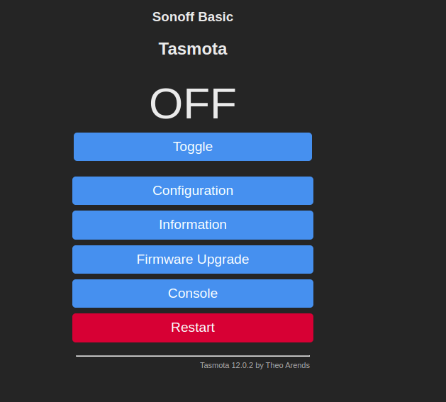
If the connection is successful, you should see a new IP address on the serial terminal. connect back to your router and type in that IP address in your browser. If the setup was successful you should be greeted with a page like this.
Tasmota Templates


Normally when using ESP8266 you would have to write code to make it do stuff for you, but with Tasmota templates you just have to set certain parameters and you are good to go.
To get started, on the home page click on Configuration and then Configure templates. You should have something like this on your screen.

In the name text box, you can put any name you want, in the based on drop-down, you are to choose a device on which your template will be based, but for this article, we would use Generic. If you click on any of the drop-downs for any GPIOs you would see things like buttons, Led, PWM etc. The scope of this article will only be covering buttons, LEDs and relays.
Buttons
Buttons are simply physical inputs, so if I wanted to control the onboard LED connected to GPIO2 via the flash button connected to GPIO0 on the ESP8266, my template configuration would be like this.

From the image, you can see I choose button 1 and led 1, this means that if you want a particular input to control an output, in this case, our LED, the led and the button must have corresponding numbers. The same applies to relays also. After selecting the correct button and LED click on save to save the template, but we aren't done yet, we still have to activate our template. After the template has been saved you should have a button main menu click on it to go back to the home page. On the home page click on configure and then click on configure other. If you followed the steps correctly you should see be seeing this.

check the activate box in the template section to activate your template and click save.

Now when you are back at the home page press the GPIO 0 (flash button on your ESP8266, and the onboard LED should toggle. A video demonstration is above.
Relays
Relays work the same way as buttons but they are virtual; If you choose a relay instead of a button a virtual button will appear on the home page which we can use to toggle an led. Set up your template like this

then when you go to the home page, you should have something like this

Tasmota Pre-built Template
Making things easy is hard _ted nelson_
Someone put in a lot of hard work to create a repository containing various templates for esp8266-based smart devices, so we have a bank of ready-to-use templates to make using Tasmota easier. To access the site click here.
- On the site click on development boards.
- Scroll to Adafruit HUZZAH ESP8266 Development Board and click on it.
- Copy the configuration from the web page.

Then go back to the config web page of Tasmota and navigate to configure other and paste the configuration you copied into the template text box and click save.

Now when you press the GPIO 0 (flash button) on the ESP8266 the LED will toggle. You can apply these same steps to other templates in the repository.
Tasmota makes it very easy to build a home automation system without code, imagine turning your regular home into a smart home without writing a single line of code or starting a business with it. So try out Tasmota today and thanks for reading.