Getting Started With Holtek Microcontrollers
by pyromaniac303 in Circuits > Microcontrollers
15358 Views, 7 Favorites, 0 Comments
Getting Started With Holtek Microcontrollers
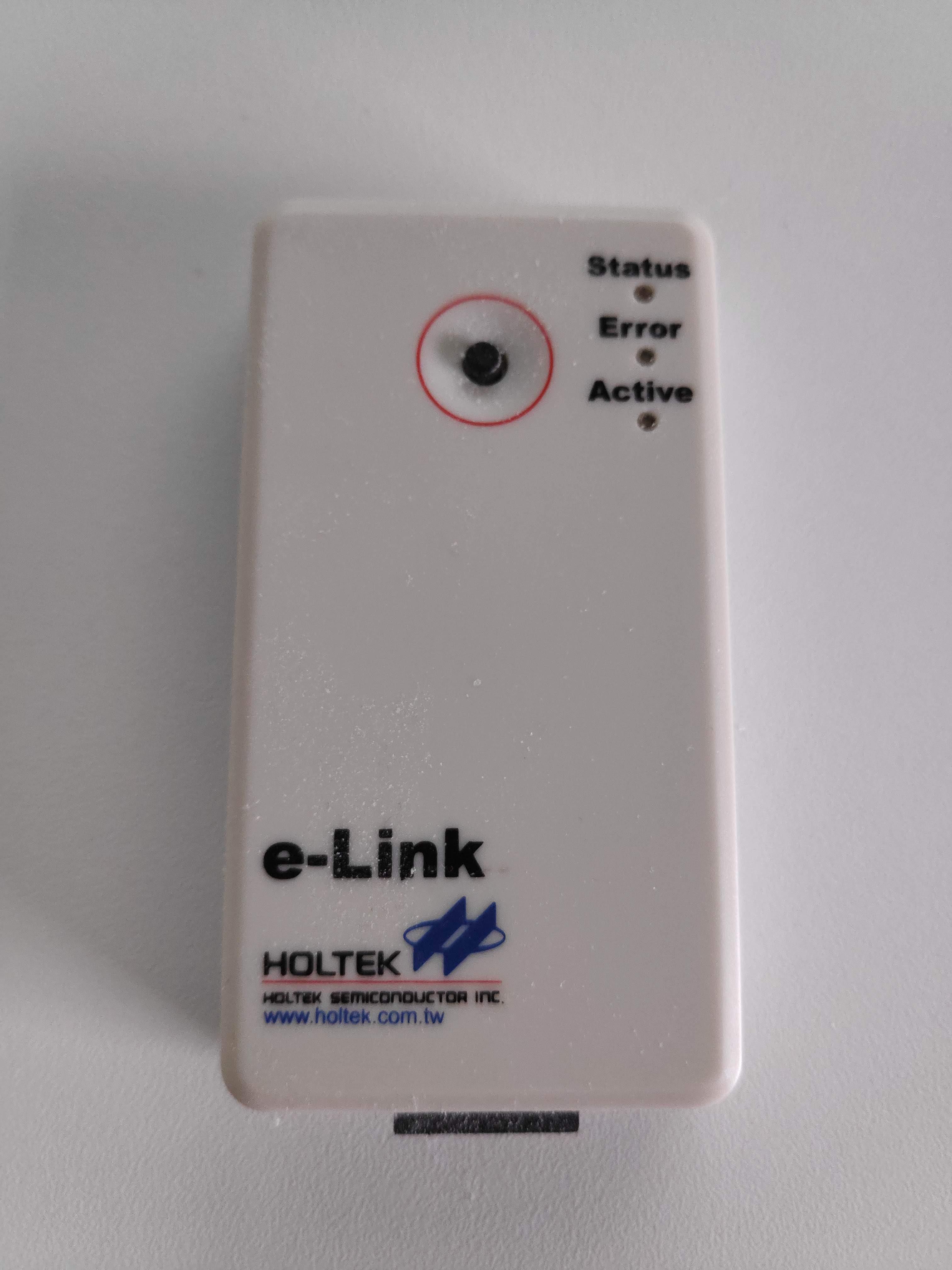
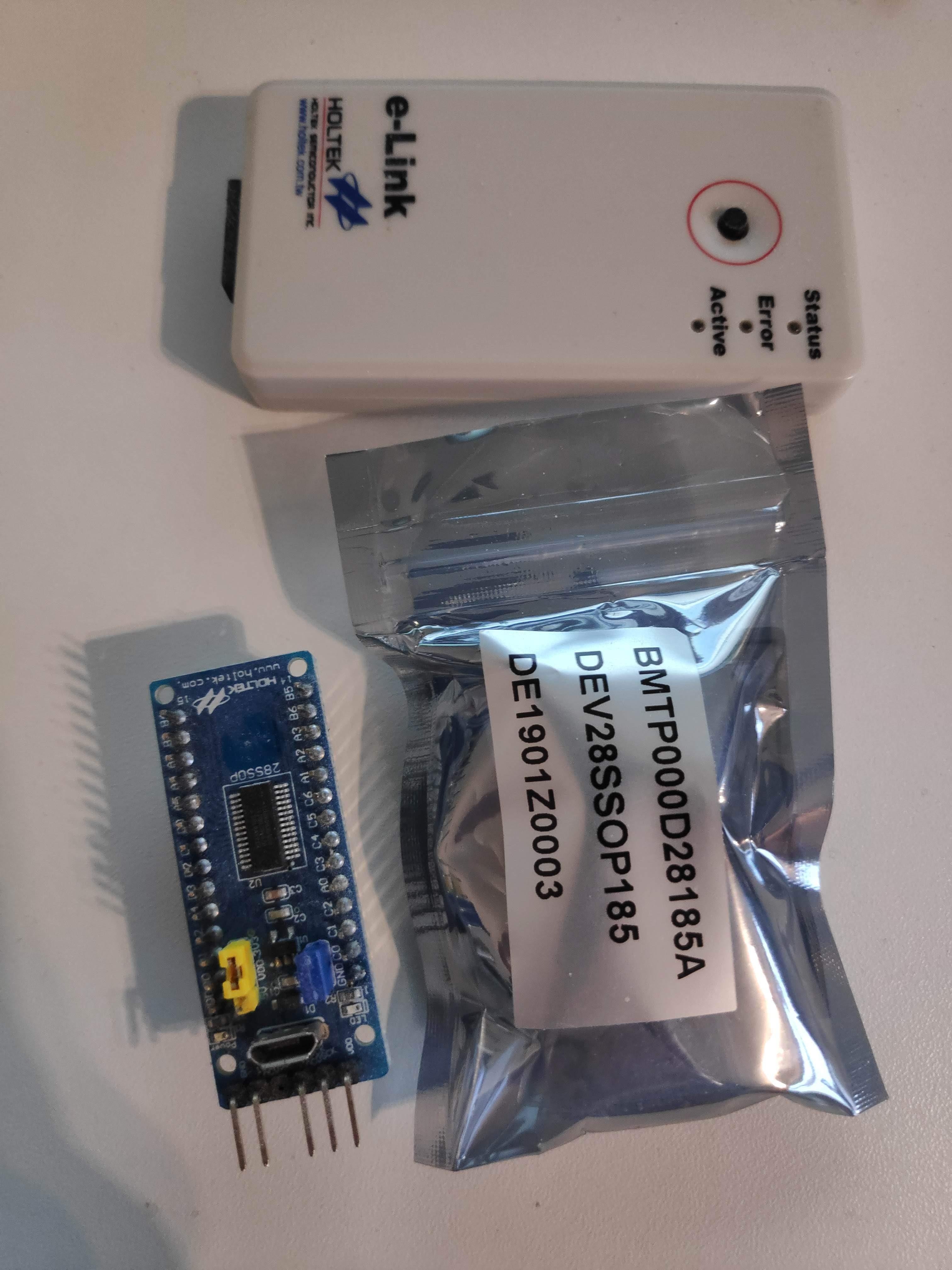
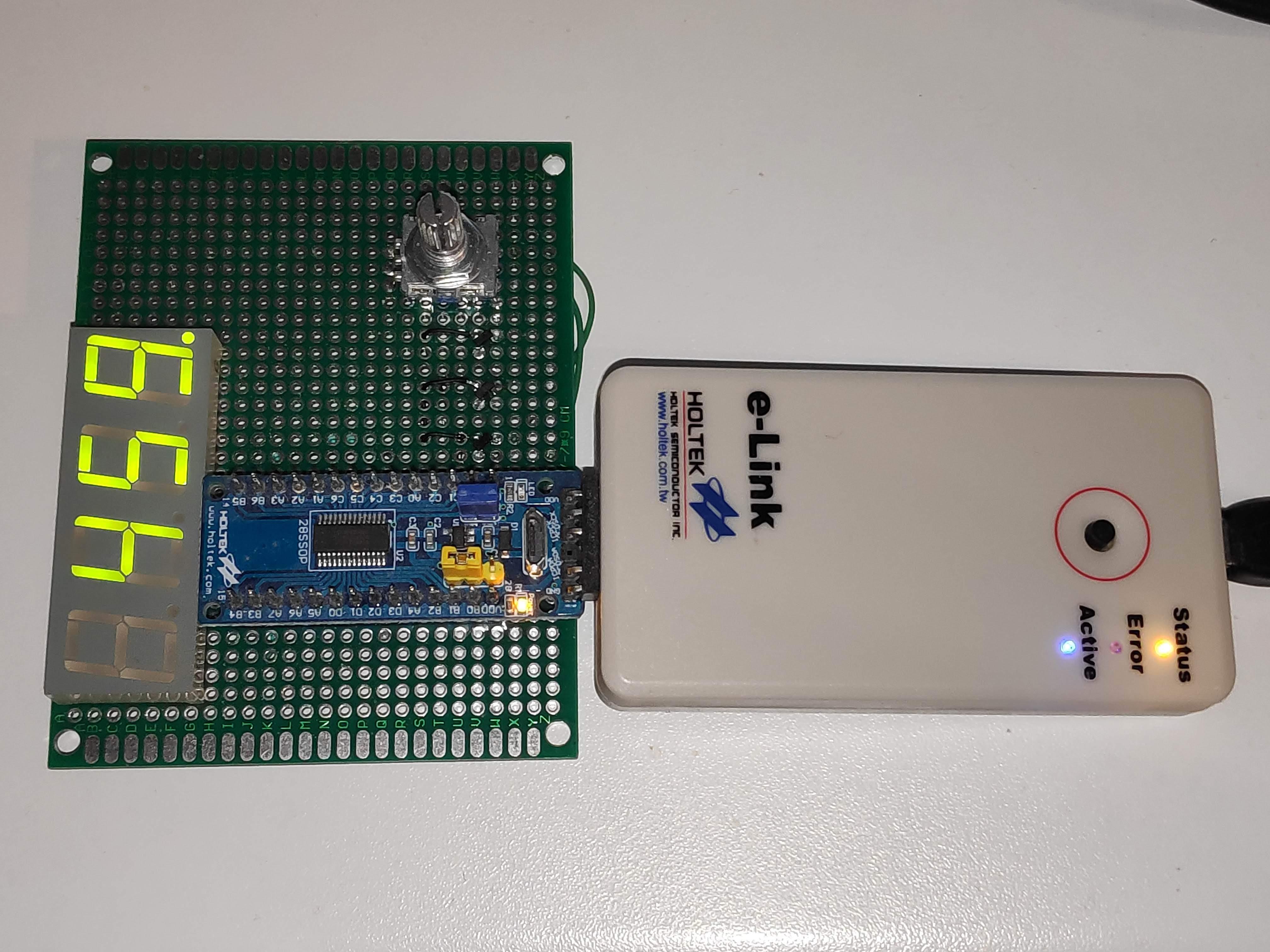
Starting with a new microcontroller platform can be a daunting step, especially when coming from a hobbyist background and only being familiar with the Arduino IDE in which a lot of the configuration is done for you.
However, the benefits of moving to such a professional platform are many:
- Greater control over setup - you can easily create hardware with power consumption in the microamp range.
- Lower cost of microcontrollers. Some of the Holtek devices are under $0.10 on LCSC!
- Expands your knowledge and makes it easier to get started with other manufacturers.
So I wanted to share with you some of my experiences / pitfalls and how to get started cheaply and easily.
Supplies
- Holtek 8 bit flash microcontroller or development board. I'll be using this HT66F0185 development board
- Windows based PC.
- Holtek e-Link programmer.
- Protoboard and parts, based on your project requirements.
Purchase Your Parts & Programmer
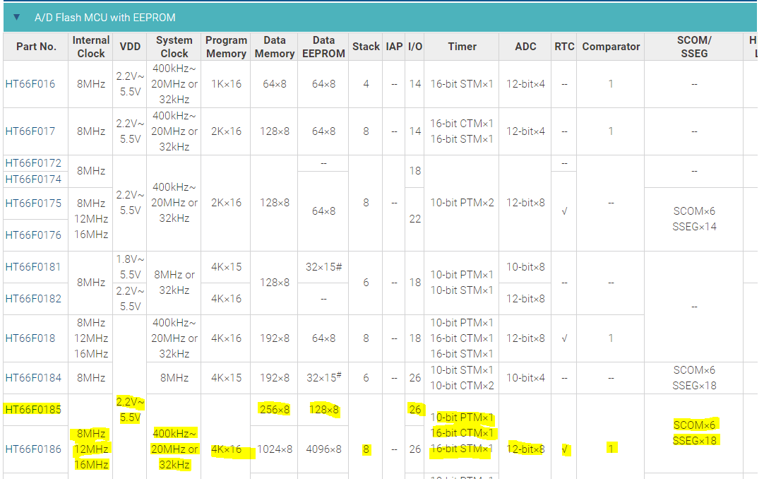
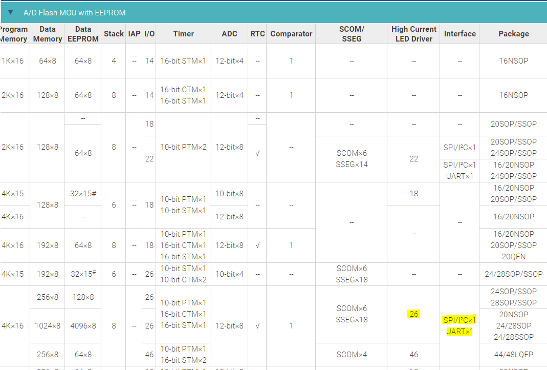
Depending on your project, you may need a small low cost microcontroller, or one with a bit more power and certain peripherals.
Whereas with Arduino you'd normally just put an ATMEGA328 in there regardless of project requirements, this is where the first difference occurs. Make a list of your project requirements (number of analogue ports, UART or SPI requirements, number of IO etc.) and select the part with the lowest cost that has all the neccessary features. You can see the one I've chosen above highlighted in yellow.
Holtek's website has quite a comprehensive parts vs. feature list for their whole range ( Product List), however bear in mind that not all of them will be available from distributors.
Next you'll need an e-Link programmer/debugger. These are available from LCSC and Best Modules and possibly some non-official sources too like AliExpress, though I have struggled to find them on eBay in the past.
Download the IDE
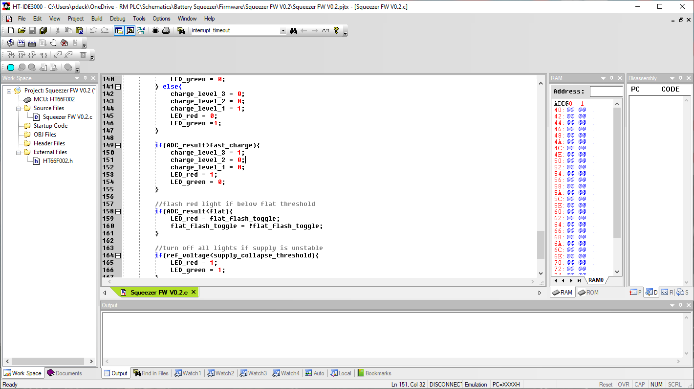
The IDE for Holtek is called HT-IDE3000. It looks a little old fashioned if you're used to the Microchip MPLAB-X or some other modern IDEs, but the tradeoff is lightning fast performance and it doesn't take long to get used to.
You can download the software at the bottom of the E-Link product page. Once installed you'll probably have to activate your E-Link if you're using it for the first time after connecting it via USB, then you're all set up and good to go.
Start a New Project
I'm going to make a couple of assumptions for the following steps:
- You have a basic knowledge of the C language.
- You can find your way around an IC datasheet.
For the purpose of our demo, I'm going to be using the HT66F0185 development board. For those coming from an Arduino background it doesn't matter whether you are using a loose IC or the development board as you've never had debug capability, but for those coming from a Microchip background it's important to note that the production IC does not have debug capability. The ones on the development board are special 'V' part numbers - actually HT66V0185, which means you can pause program execution and inspect register values, insert values and jump to different sections of code - all very useful. You can also obtain the special debug ICs from a Holtek rep if this is going into large scale production.
At first I thought this was quite limiting (most Microchip parts have debug built in, even on the production ICs), but then I realised that this represents quite a large cost saving, as 99.9% of the production ICs will never be plugged in to a debugger, so it's a huge waste of silicon area.
To start a new project, select 'Project -> New' within the HT-IDE3000 top menu bar.
Type in your project name, location and select your MCU.
The next option 'Choose Language Tool' will depend on which IC you have chosen - the cheaper and more basic ones such as HT66F001 will only support older versions, but in this case for the HT66F0185 we can choose version 3. In my opinion the V3 is much better and closer to real C.
Next we get a warning about unbounded pins - this just means that if you have for example a 28 pin package, but they also make the same chip in a 44 pin package, there will be unconnected pins. It's good practice to define what to do with them in your firmware so that no unpredictable behaviour occurs. Hit Next to automatically create a .C file for your project.
Rather helpfully we get a configuration screen next - this allows us to set the project options up. Set SysVolt as your power supply voltage - the reason this is so important is that some ICs have multiple clock options, and the higher speeds are only available above certain voltages. In my example if I set to 5V I unlock 8MHz, 12MHz and 16MHz, but at 3.3V the 16MHz option disappears. Set your Vdd, OSC (in my case internal RC + IO1/IO2), HIRC which is your running speed, and I set my fsub clock to LIRC (internal slow clock) as I was not using a Real Time Clock in this application. Hit OK and then OK again on the Project Settings, the defaults in most cases are OK.
Hardware
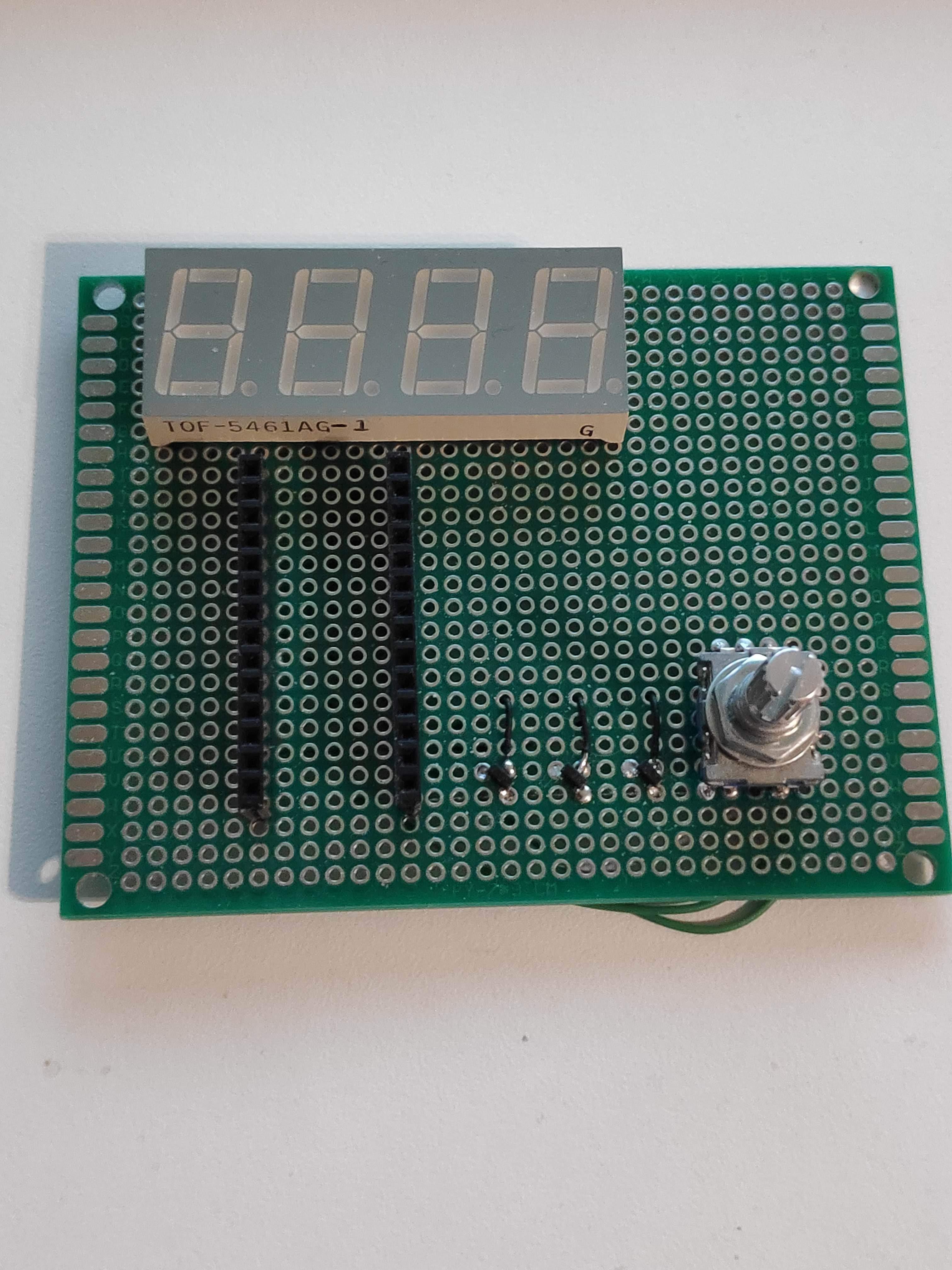
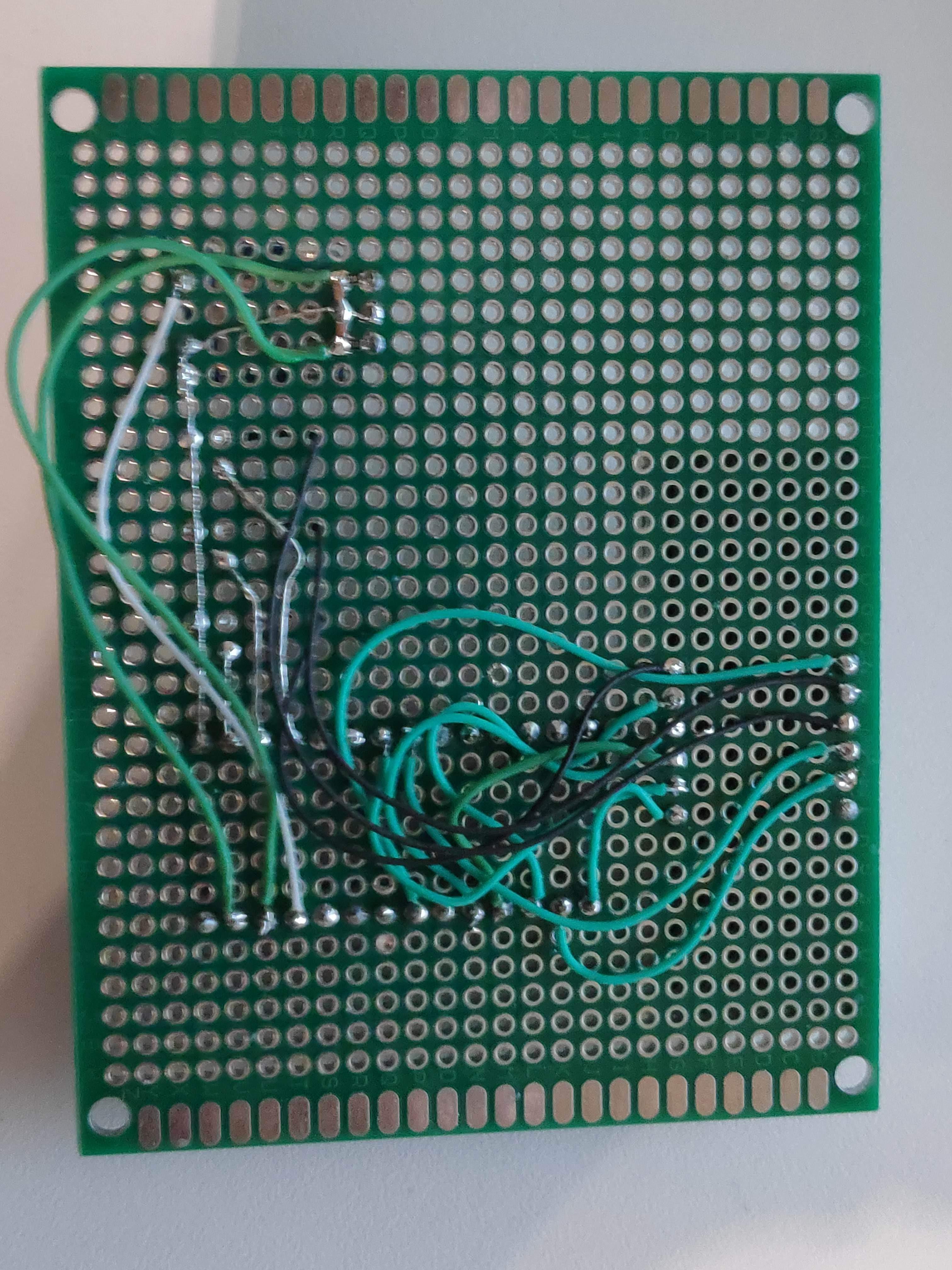
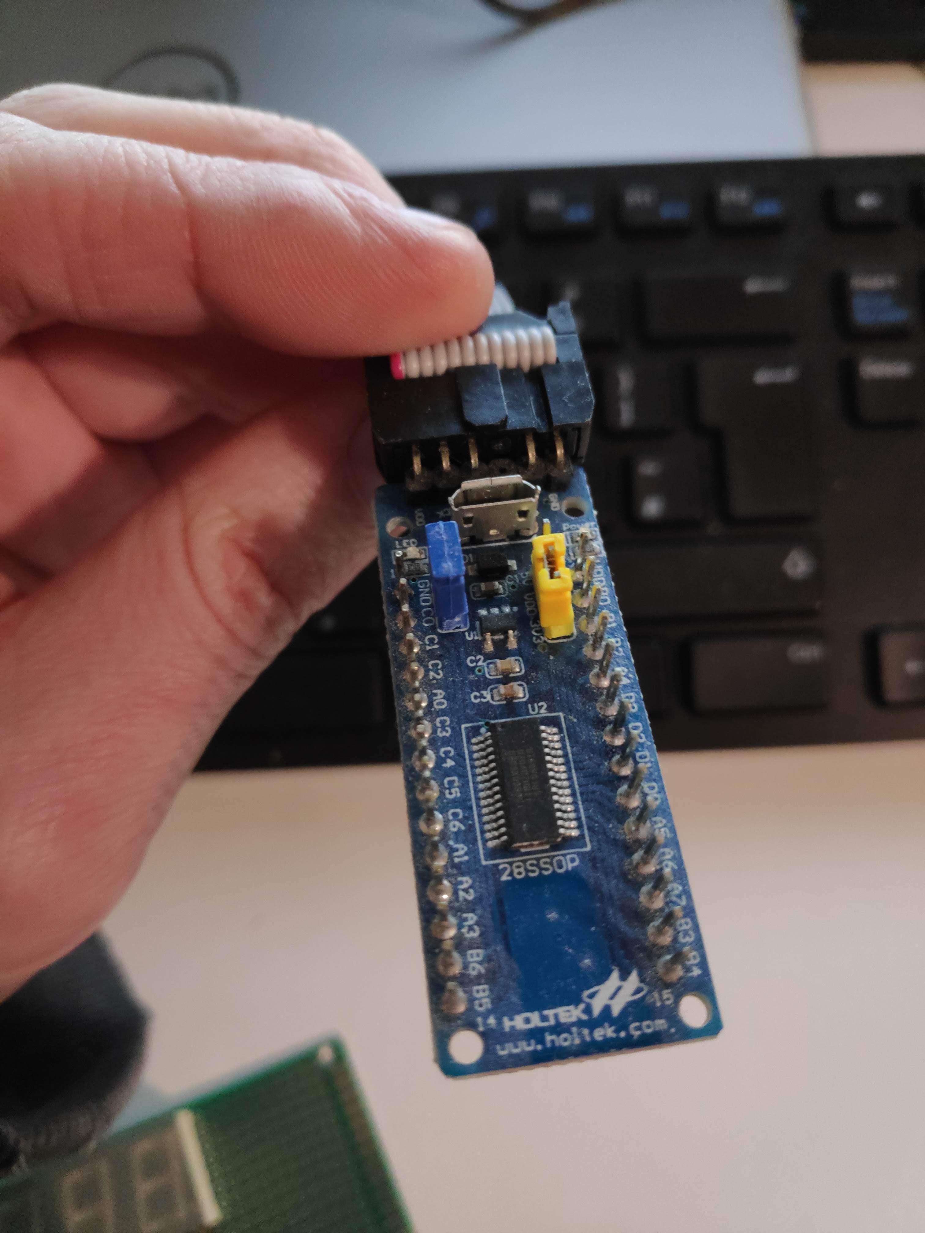
For my demo project, I decided to make a simple 3 digit counter with a rotary encoder and a 7 segment display.
I built this up on prototyping board, with removable SIL headers to plug the demo board in. I also used the included ribbon cable to connect my development board to the e-Link - even though it's double-row, you only need the side with the blanked-off pin connecting.
For those of you who studied the photos of the board, you might think I missed a step by not including any resistors on the 7 segment connections, but this microcontroller contains a really useful feature (I/O Port Source Current Control) that allows you to select the I/O port current and drive LEDs with no resistor, in 4 steps.
Config
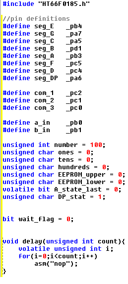
Although the Holtek configuration automatically assigns your ports reasonably accessible names, it's pretty hard to remember in 2 months time that you connected Port B pin 1 to segment H for example, so my first step is always to define human readable names to the pins, so that if I have to revisit the code I don't have to trawl through schematics and datasheets. These all go above your main routine, along with your variables.
If you chose a more basic part and had to use the V2 or below C compiler here is where you'll notice the first difference - in V3 we can assign a starting value to a variable (e.g. unsigned int number = 100; ) whereas this would flag as an error in V2. To get around this limitation we would have to just put 'unsigned int number;' in our variable declaration then somewhere in setup routine write a second line 'number = 100;' before the variable was needed for anything.
Additionally if you're coming from an Arduino background, you'll probably be used to creating accurate delays effortlessly by calling delay(), but no such luck here! You will have to create your own delay routine, or generate one using the Tools -> V3 Code Generator like the image above. The delay will be in CPU cycles however rather than milliseconds, so the length will depend on what clock speed your chip is running at. It's worth pointing out that the CPU clock runs at 1/4 the speed of the oscillator, so a 16MHz clock will result in 4 million operations per second, much like many of the PIC microcontrollers.
Setup
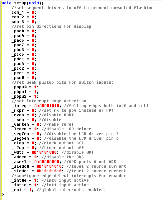
Note that Setup is created automatically in Arduino and runs at the start of the program execution, whereas in the Holtek environment you're just given a Main() loop. If you want to create a Setup routine, you need to make it yourself and call it from Main. Many times I have spent wondering why my pin directions aren't configured correctly, only to realise I haven't called Setup()!
Go ahead and create it, then set up your IO port pins. In this case, I wanted to set all my display pins to outputs. Each IO port has it's own direction control register - for port A it's called PAC, for port B PBC and so on. You can access each bit individually, for example '_pbc4 = 1;' will make port B pin 4 an input, or '_pbc4 = 0;' for an output. Additionally there are weak pullups built in to most Holtek IO ports (internal resistors which can be set to pull switch inputs high), which saves the need to add external resistors. They're accessible via _pXpuY, where X is your port, and Y is your pin number. 1 enables the weak pullup and 0 removes it.
It works in much the same way for all the peripherals - if you want to set up a peripheral, have a search in your datasheet to find what registers need to be configured to make it work. The descriptions are quite comprehensive, but don't be disheartened if it doesn't always work the first time round. How to access the registers is defined in the part .h file, which is automatically assigned when you create your project and can be found in Workspace under External Files. It's worth noting that you should not edit it, as it will change for all the projects it's associated with!
I'm going to gloss over the rest of the configuration as it's beyond the scope of this getting started guide, but it's worth a good read through your part datasheet if pins aren't operating correctly to make sure they aren't defaulting to analogue ports or UART pins etc.
After writing the setup routine, I added more routines to configure the output for each digit and strobe between the ones, tens and hundreds column, and two interrupts which would detect when the rotary switch was turned.
Main
First within Main, let's not forget to call our setup routine!
But wait - if we do that then every time the Main loop runs, setup will run again which is at best inefficient, and at worst could set values back to their default state and cause strange goings-on.
The solution is to put the rest of the program into a permanent While(1) loop, which it can never escape from. The only way it escapes is when one of the functions we created earlier is called, or an interrupt occurs, but then it will return after the function or interrupt is complete.
Within this loop I add a few rounds of strobing through the digits, a switch-case statement to toggle the decimal point display which allows us to edit the ones, tens or hundreds rather than rotating the dial 999 times, and a small delay that disables the interrupts for a few milliseconds when the dial is turned. This is to prevent one click of the dial causing multiple digits to change, as the switch was quite 'noisy'.
There's also some junk in there where I planned to store the value in EEPROM and recall it at start-up, but didn't finish it yet. I've uploaded the code to this instructable for anyone that may find a use for it.
Downloads
Running and Debugging
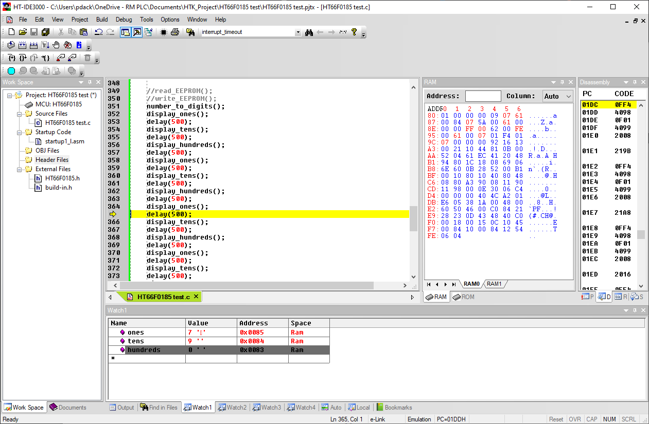
For those just with a 'F' part, plug in your programmer, compile your code (Shift + F8) then press the ICP button icon that looks like a blue page with a down arrow. This will bring up a menu allowing you to select the programming voltage, and initiate programming. If all is wired up correctly, it should be a matter of seconds, you can then self-power your circuit through the programmer to test it.
For those lucky enough to have a 'V' part or a development board, you can compile (Shift + F8) then hit Go (F5) to enter debug mode. Your program will then begin to run, you can reset with F4, or click on any line of code and press F9 to add a breakpoint - this will stop the code from running when it reaches a point of interest.
When you reach a breakpoint, you can add variables to any of the 4 Watch tabs at the bottom by right-clicking and 'add variable to watch window'. This will display their value, and allow you to check your program is doing what you expect it to, or diagnose errors. It's also useful to find out if a section of your code is actually being executed, by setting a breakpoint there. If it doesn't stop running then you know it's never reaching that line.
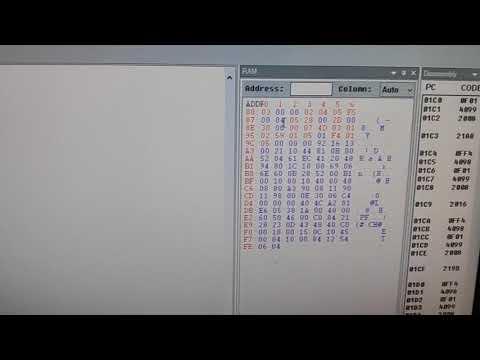
Also useful is that when you stop on a breakpoint, the whole contents of RAM and ROM are downloaded and items that differed from last time it stopped are highlighted in red, which allows you to see what variables are being changed. If this is not shown, open it using View->Toolbar->RAM.
Conclusion
I hope this Instructable inspires you to take the next step in your hobby or career, and makes swapping to a new microcontroller platform a little less daunting.
I'm happy to answer any questions in the comments below.