Getting Into World of PLC Part - II
by Aerobot09 in Circuits > Electronics
1770 Views, 3 Favorites, 0 Comments
Getting Into World of PLC Part - II
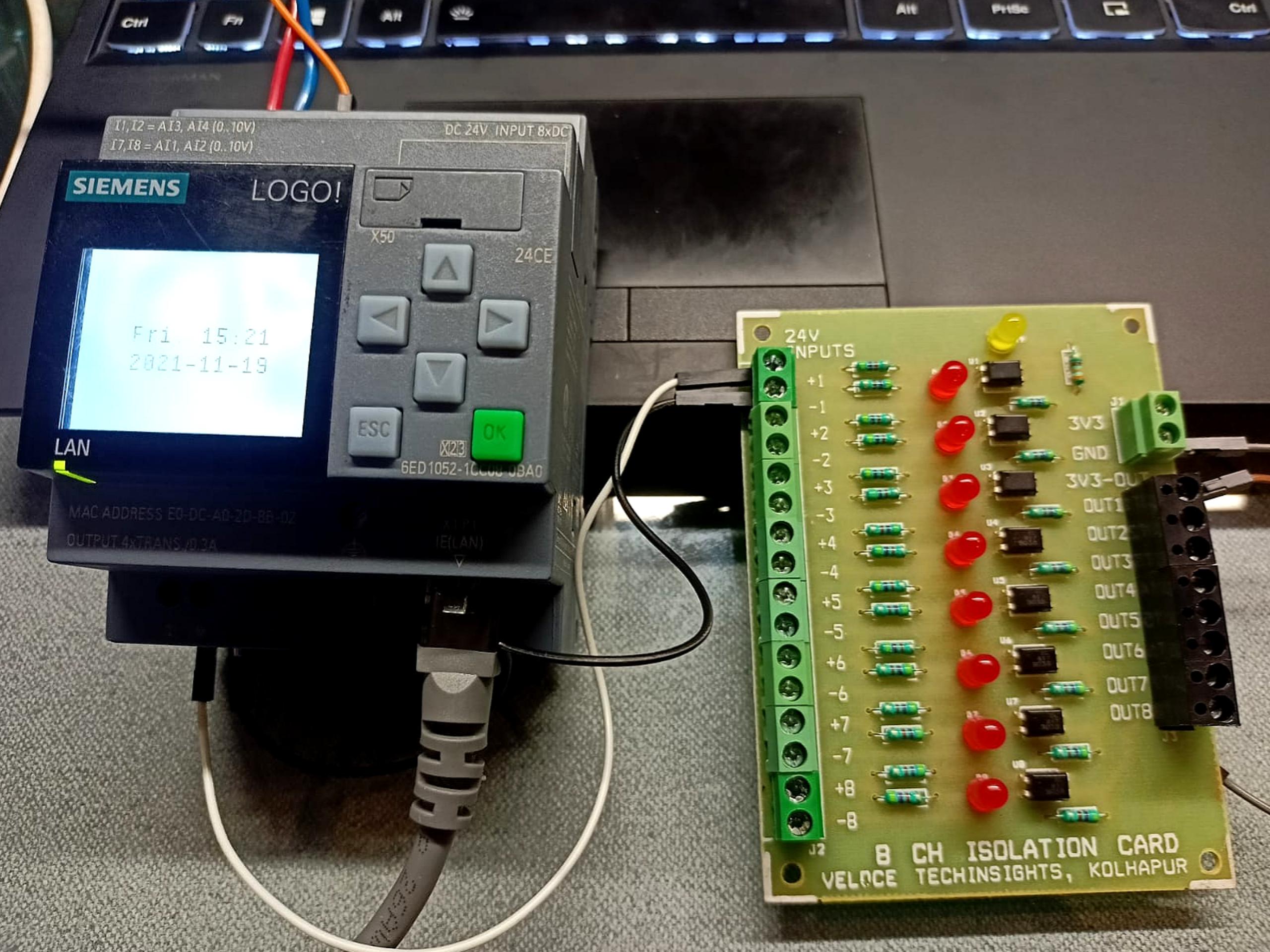
Hello there...!! How are u guys…?? Yaa I am good too…I hope you all have enjoyed the previous article “Getting into the world of PLC- Part 1”. In part 1, we saw about the basic introduction to Siemens LOGO! PLC and now are familiar with the basics. I know some of you might have been eagerly waited for the second part. As promised this article will touch on the parts of the setup, configuration and sample program for Siemens LOGO!
Supplies
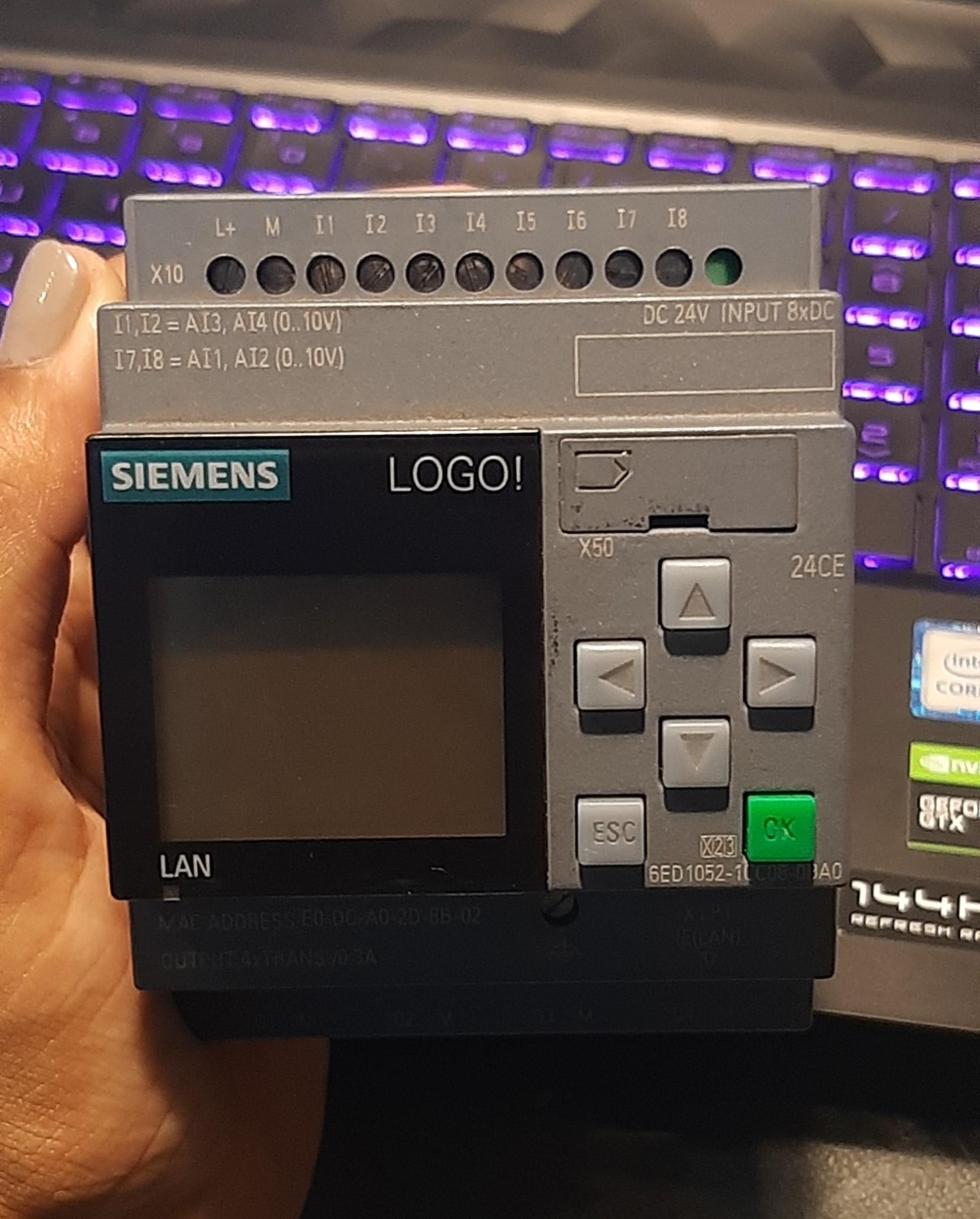
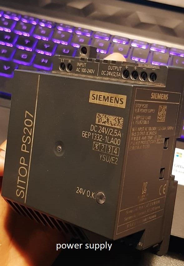
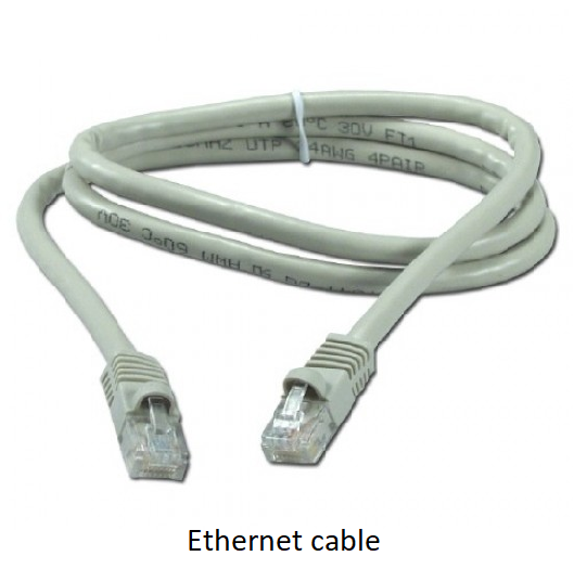
Software: Siemens LOGO! Soft Comfort
Hardware:
- Siemens LOGO PLC
- Siemens power supply
- Ethernet cable
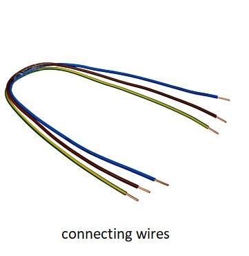
- Connecting wires
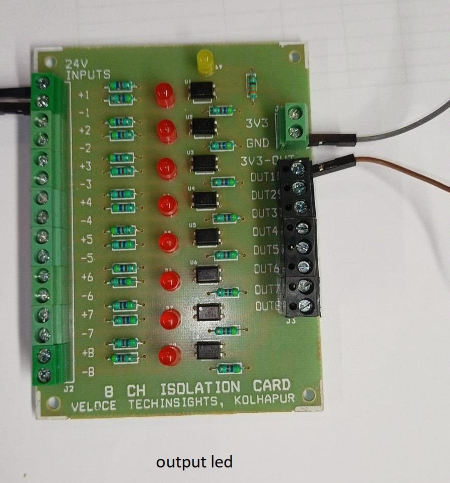
- Output (connect 24V DC led or use an appropriate resistor)
PLC: Siemens LOGO! (Setup and Configuration)
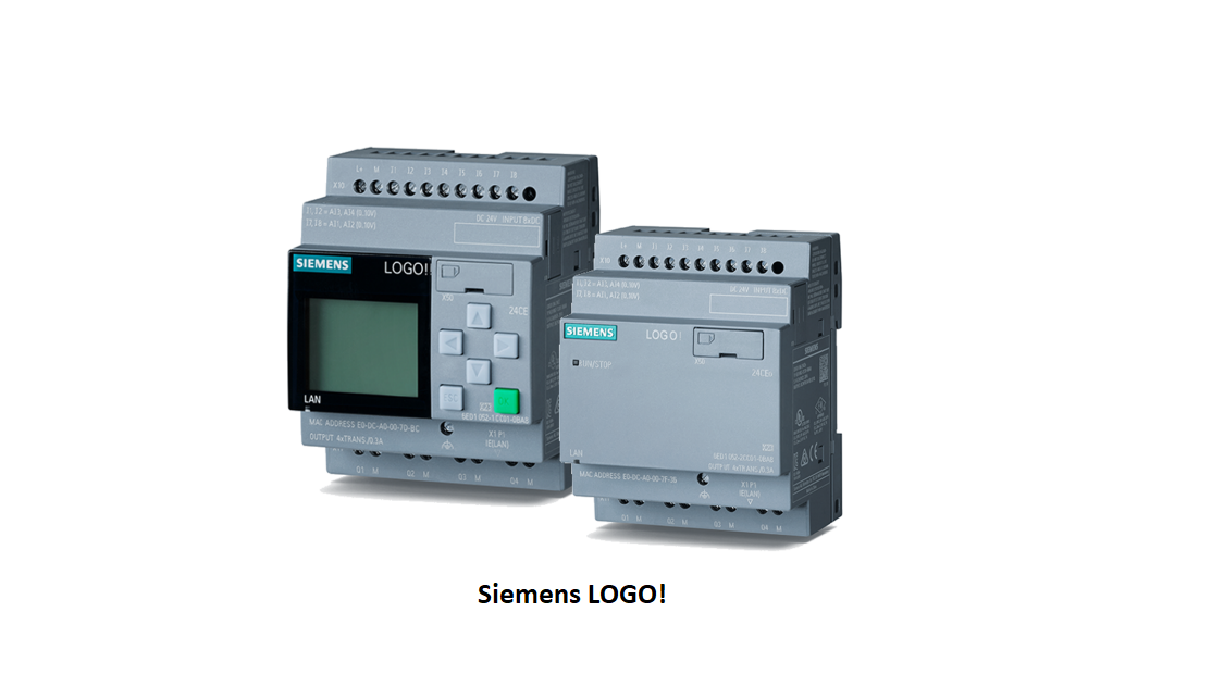
PLC manufactured by Siemens are widely used. Siemens LOGO! is a basic PLC offered by Siemens for small automation tasks in industry and building services. It is a modular device meaning it can be customized according to the requirement.
Siemens LOGO is available in two different modules:
1. Siemens LOGO with display.
2. Siemens LOGO without display.
Out of which we are going to see Siemens LOGO with display as it provides quick visual feedback making it possible for quick control of the system.
The programming software for the mentioned PLC comes with the purchase box itself, or you can follow the steps to download and install the demo version of the software. The proprietary software used for Siemens LOGO! PLC programming is LOGO! Soft Comfort.
Registration and Conformation
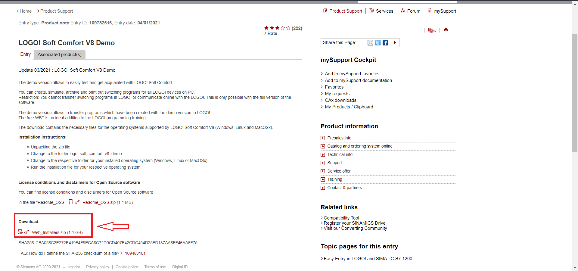
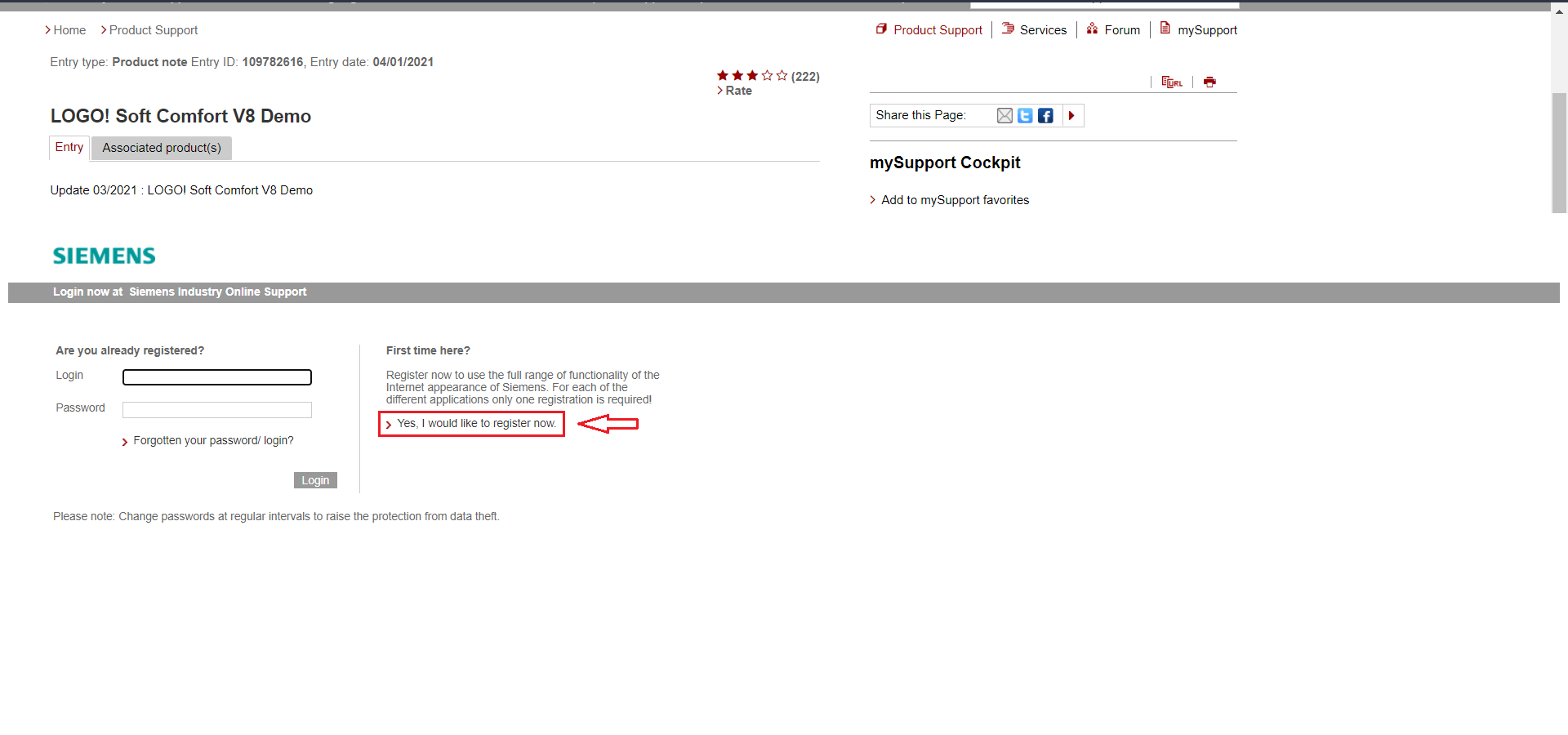
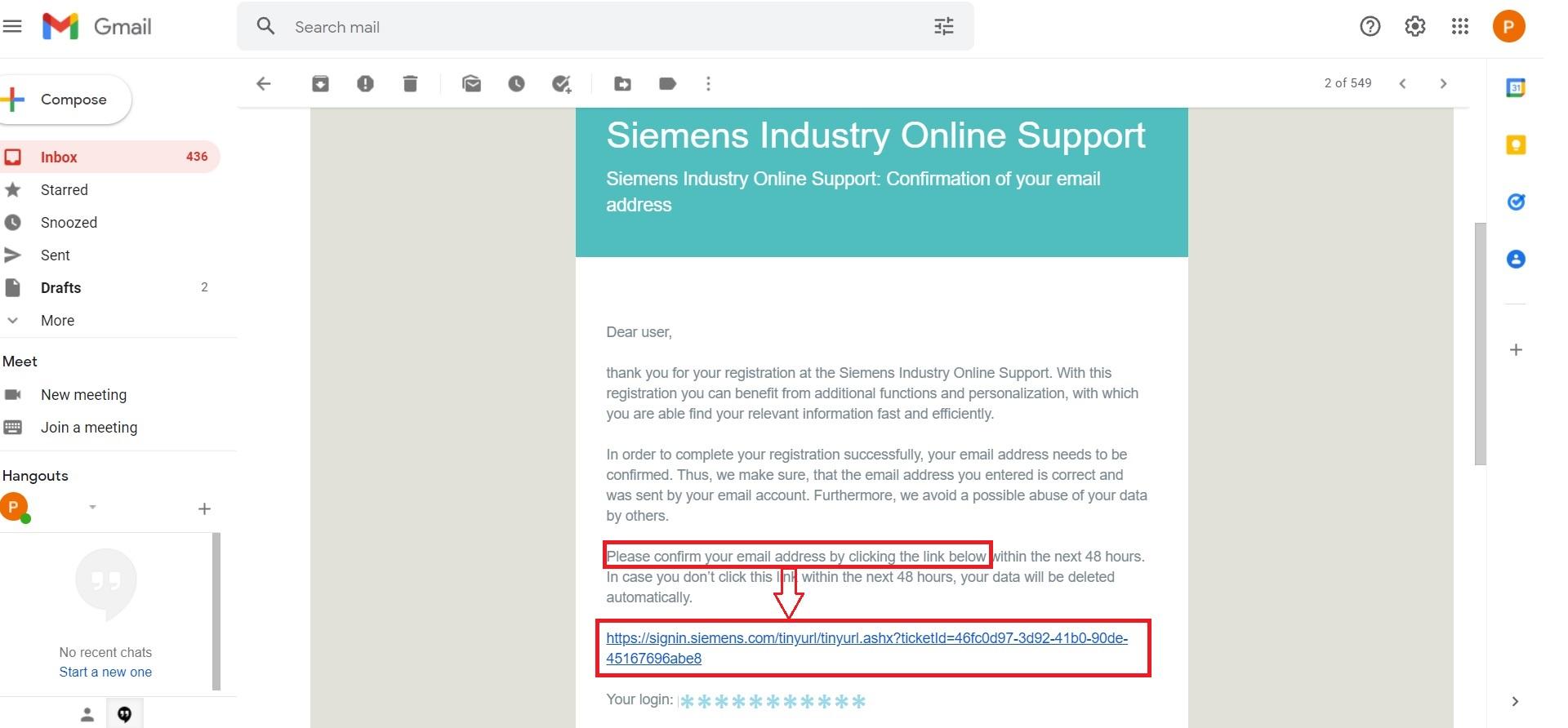
For downloading the demo of Siemens LOGO! Soft Comfort software visit here. Scroll down towards the “Download” section and click on the highlighted link.
It’ll then take you to the Login page. For the users who don’t have a Siemens account, you can create an account by clicking the “Yes, I would like to register now” option.
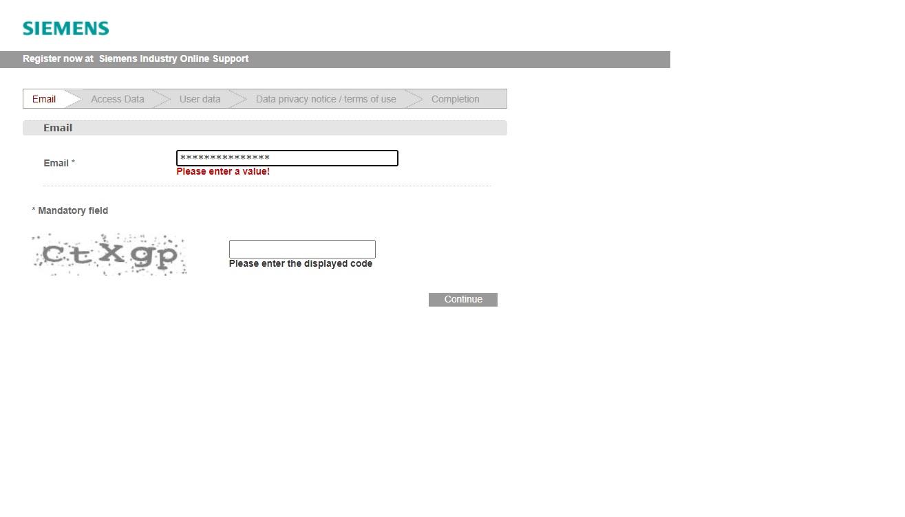
Now, you’ll see the registration screen where the website will ask you to enter the required details, you’ll need to complete all the following steps of registration:
1. Email
2. Access Data: Fill in the required details.
3.User Data: Fill in the details and ignore the “Download of export restricted software or usage of digital products” and “Basic Technical Support” options, then click on continue.
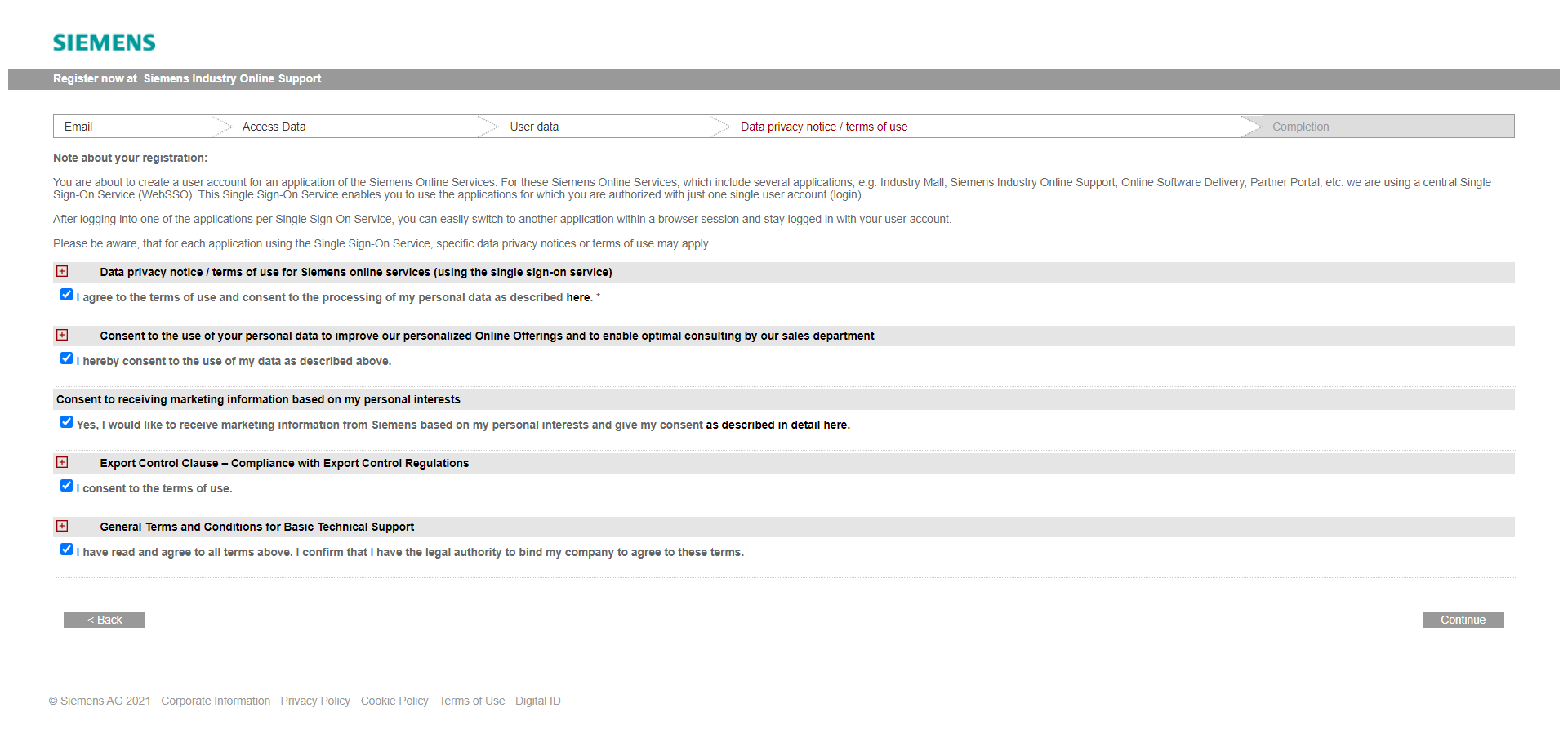
4. Data privacy notice/ terms of use: Accept all the “terms of use” and click continue.
5.Completion: Click continue once again.
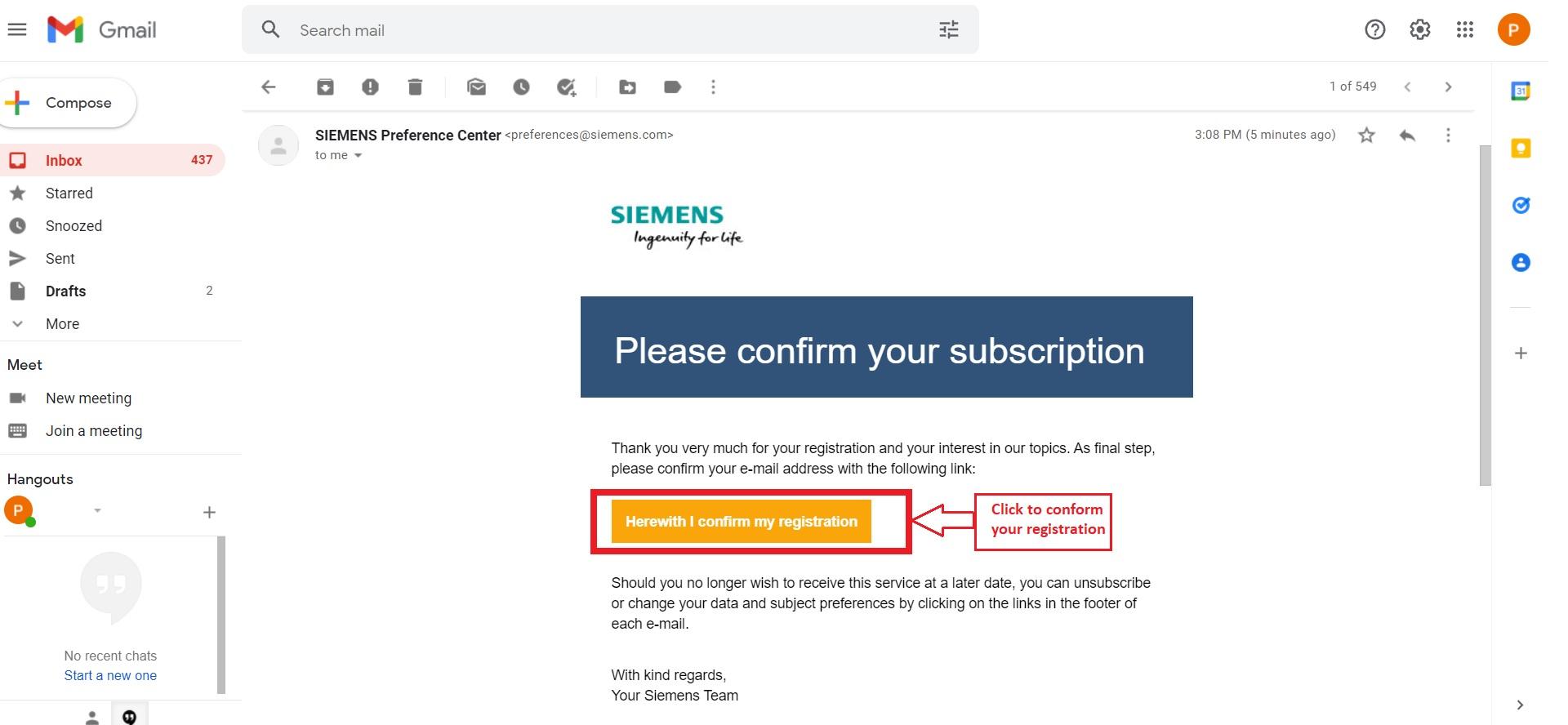
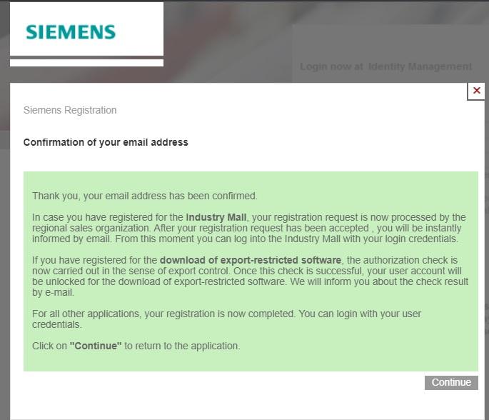
After you are done with all the registration steps you will receive a mail on your registered email account for conformation of your mail and registration. Go to the mail and click on the link for conformation of mail. Also conform your registration from another mail received. As shown in the image you will get a green color note after successful conformation of email and registration. Click continue for proceeding.
Downloading and Installation
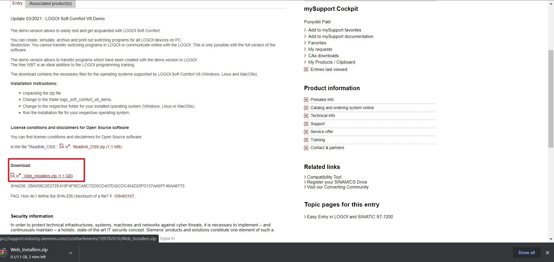
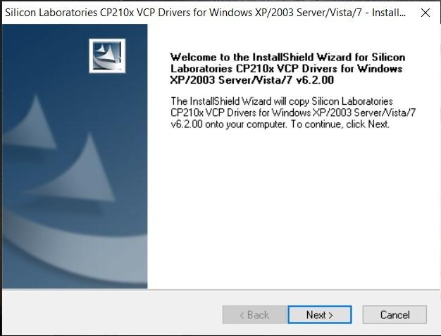
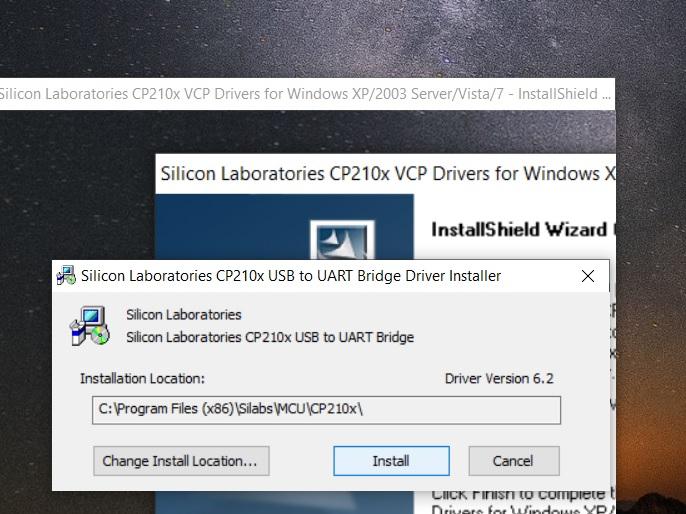
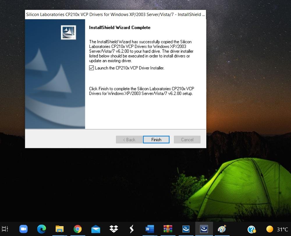
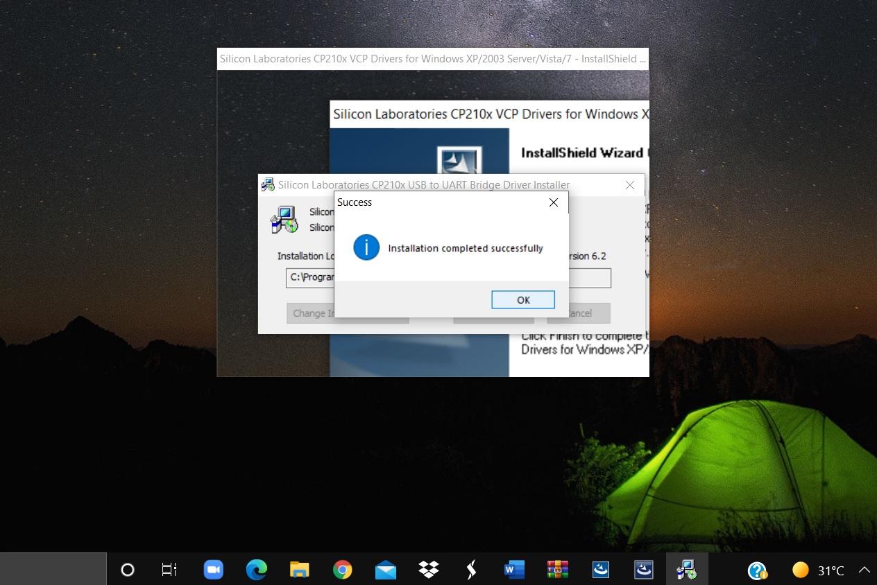
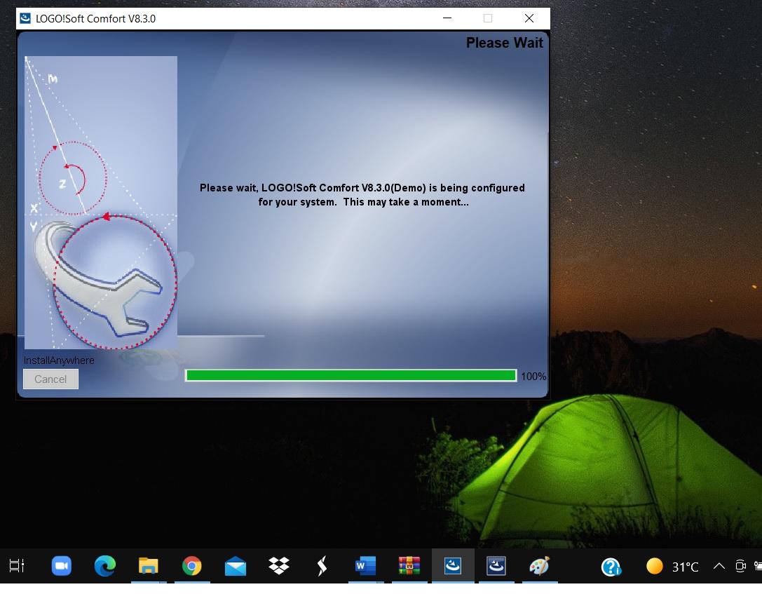
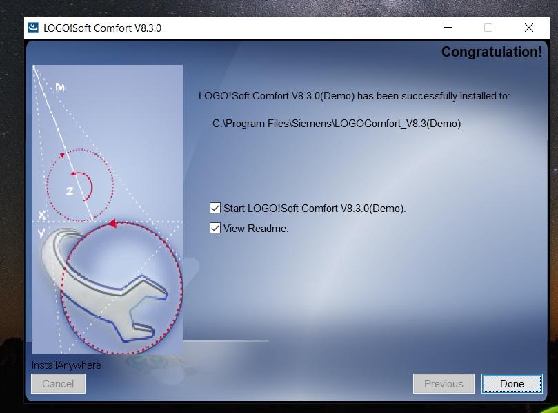
Once logged in:
1.Download the zip file and run the setup.exe file that is suitable for your PC. According to your PC configuration Run the .exe file i.e., Win64, Win32, MacOSX, etc.
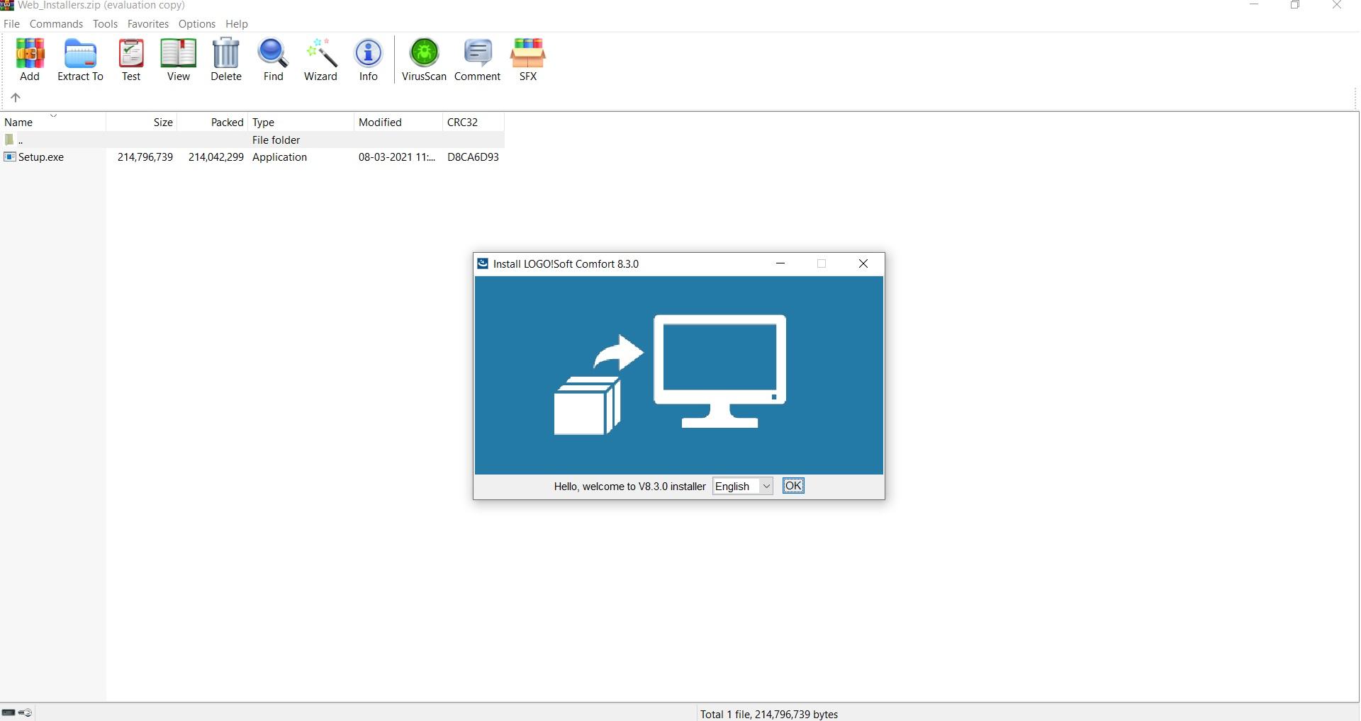
2.Next, you’ll need to extract after downloading then run the “Setup.exe” file.
3.Installation for LOGO! Soft Comfort will pop up, click ok and then accept the terms for installation.
4.It will ask the permission for the installation of Shield wizard, grant the permission.
5.Accept the terms and conditions that will pop up in the process.
6.It will automatically select the installation location. If not then assign it to the C drive of your PC.
7.Click “Finish” and on the next screen click “Ok”. This will install the software completely.
Familiarization of User Interface
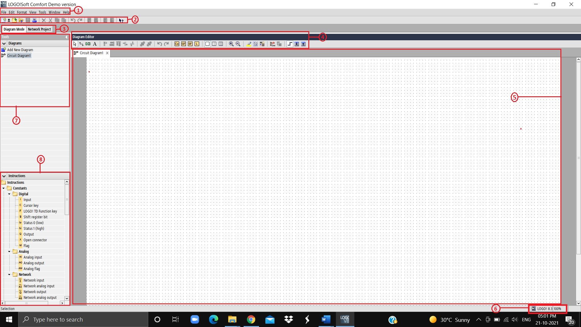
An icon will appear on the home screen and in the “Start” menu, click on the application icon to start the LOGO! Soft Comfort software. It is specifically used for the programming of LOGO! devices from Siemens. As shown in the image screen will appear once the application is started.
Refer the label in the image
1. Menu bar
2. Standard toolbar
3. Mode bar
4. Programming toolbar
5. Programming interface
6. Status bar
7. Diagram tree
8. Instruction tree
Setup
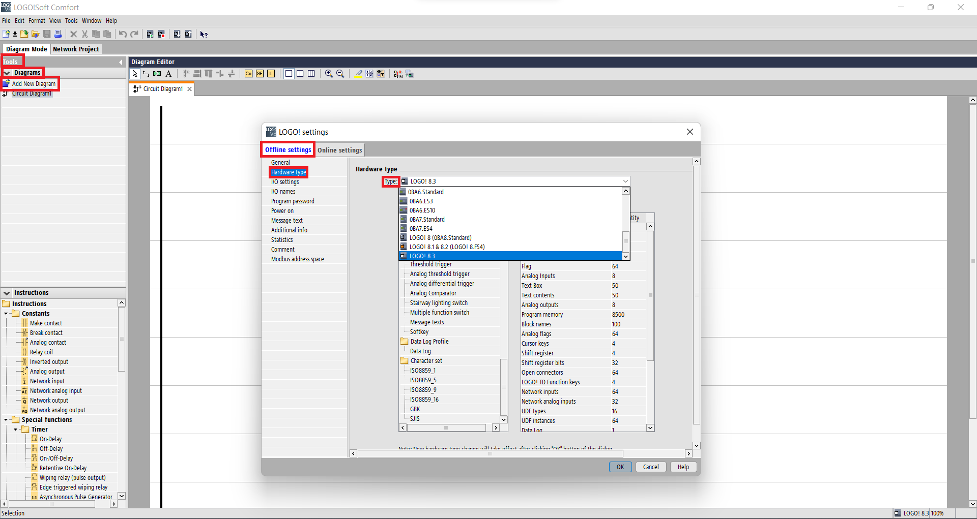
For trial on actual PLC:
- Start the LOGO! Soft Comfort software.
- Establish connection between PLC and the PC.
- Go to ----> "Tools" ----> "Diagrams" ----> "Add New Diagram". Double click on add new diagram.
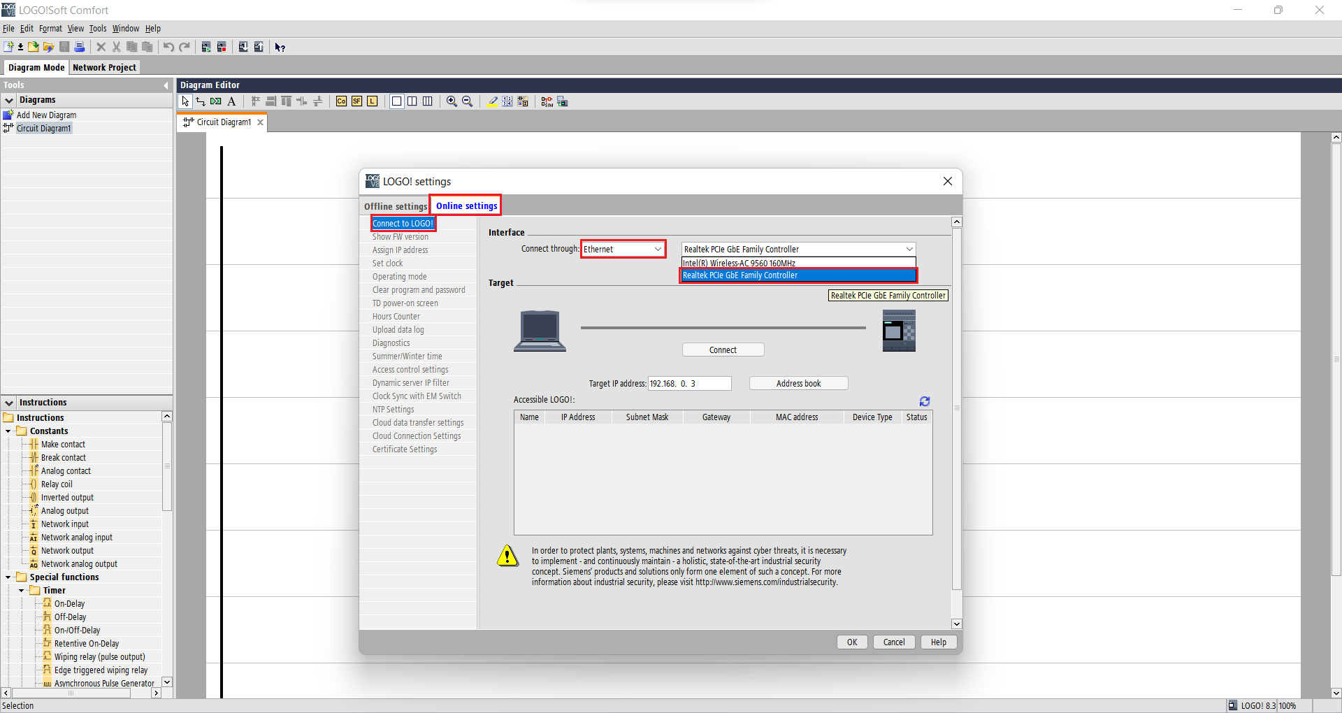
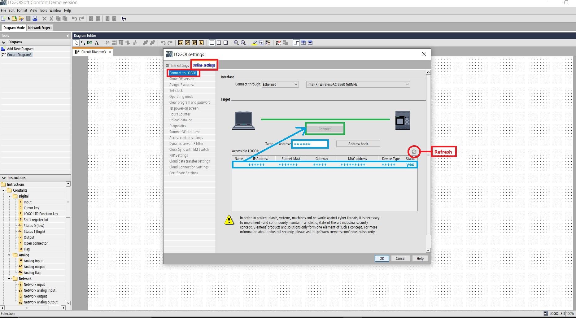
- In the “Online Settings” tab beside the “Connect through” option make sure “Ethernet” is selected, if not then select it from the scroll-down menu. Then, just beside that select the “PCIe Controller” through the scroll-down menu.
- If your PLC is automatically located with the correct IP address then is good, if not found then click the refresh button just above “Status” and then select the correct IP. Now press the “Connect” button.
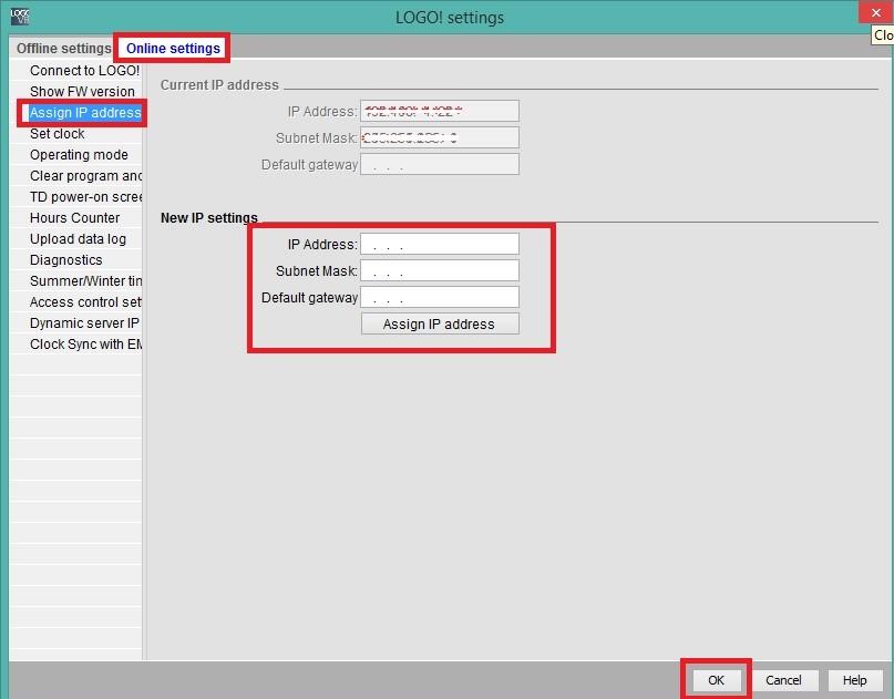
- Under “Online settings” tab itself in “Assign IP address” sub-menu assigns a new IP address and then click “OK”.
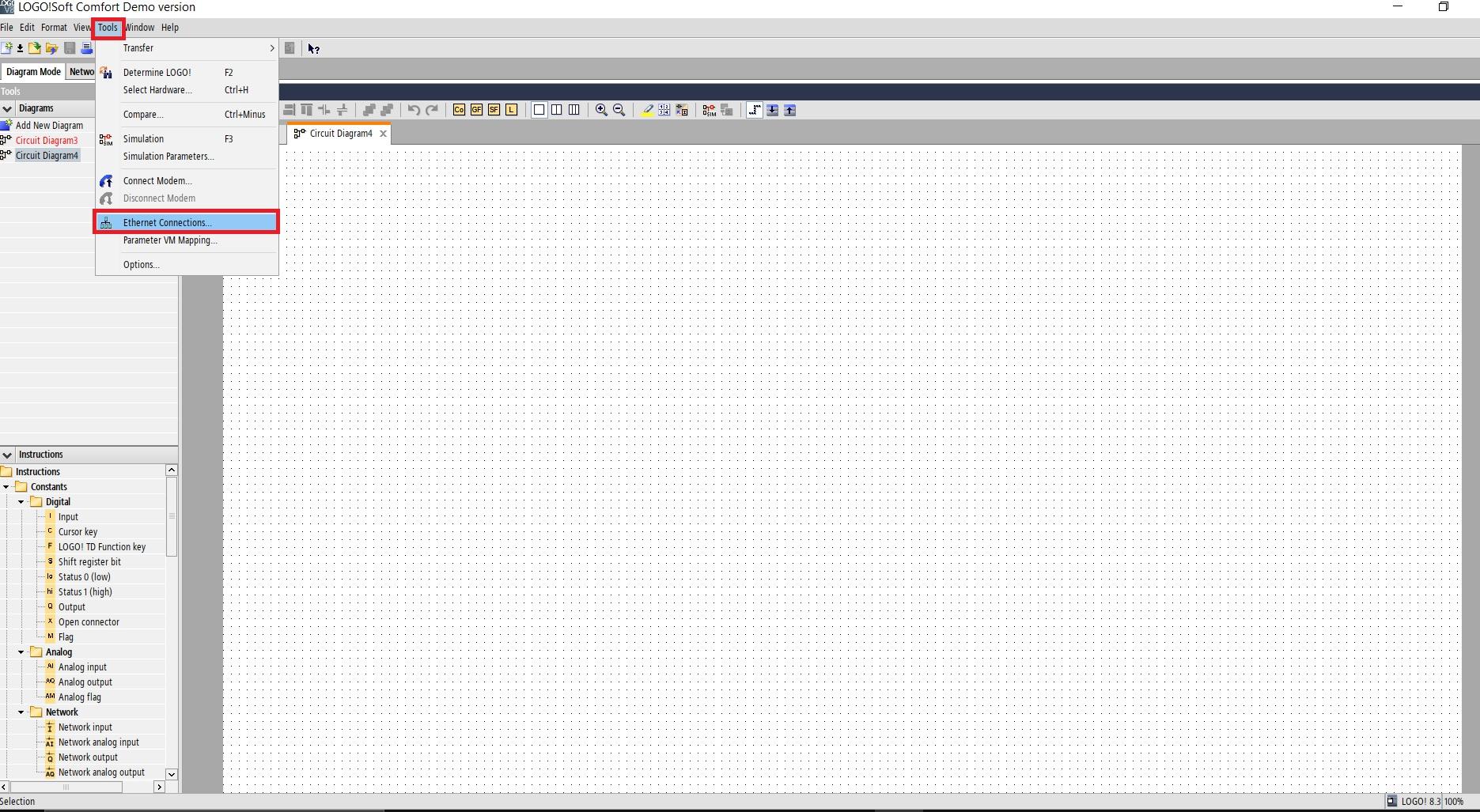
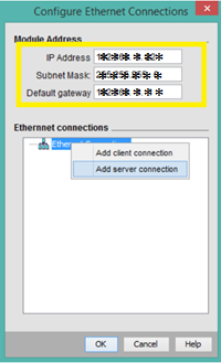
- Open Ethernet Connection from “Tools” tab located in Menu bar.
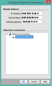
- Fill the required fields then Right-click on Ethernet Connections and press “Add server connection”.
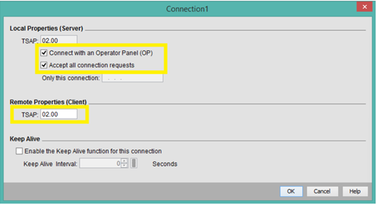
- Now, double click the created connection and check the checkboxes of “Connect with an Operator Panel (OP)” and “Accept all connection requests”. Then set the TSAP to “02.00”.
- A screen titled “Diagram Editor” will appear. Here you can start programming. By dragging and dropping various pre-sets from under “Instructions” tab on left side of the screen.
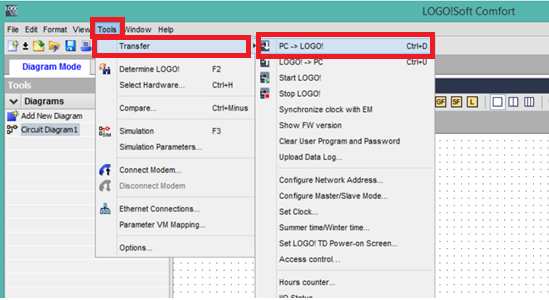
- Now transfer the newly created program to the PLC. Under the “Tools” tab from “Transfer” select “PC -> LOGO!”, or you can find the same option within the “Standard toolbar”.
For Simulation
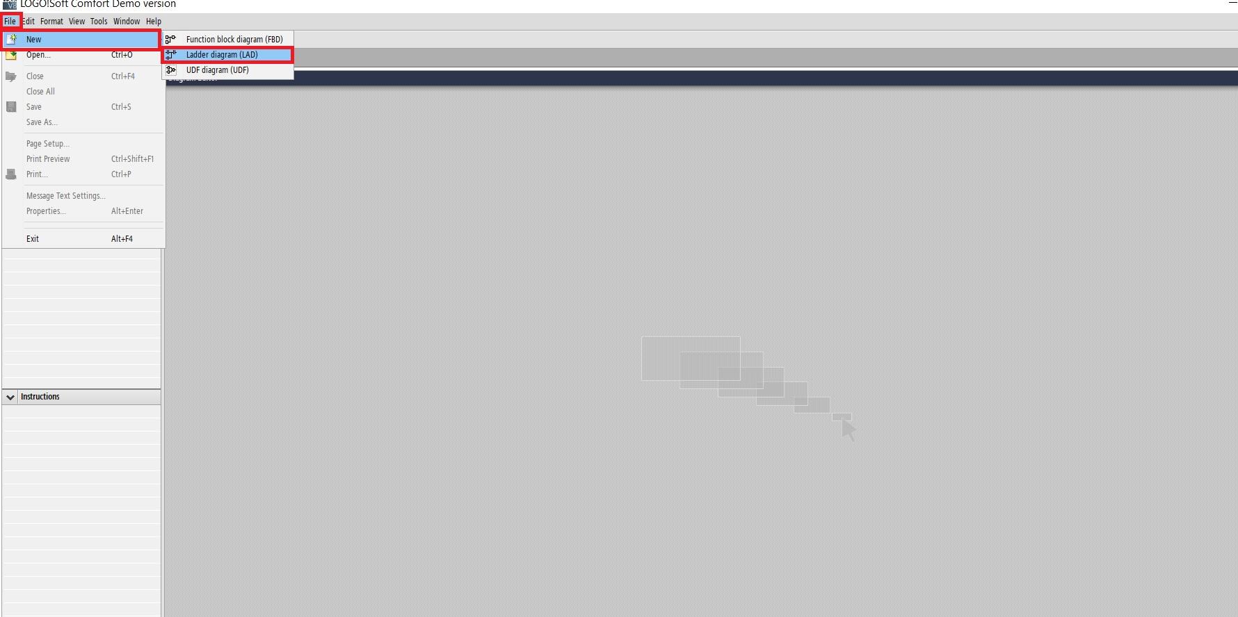
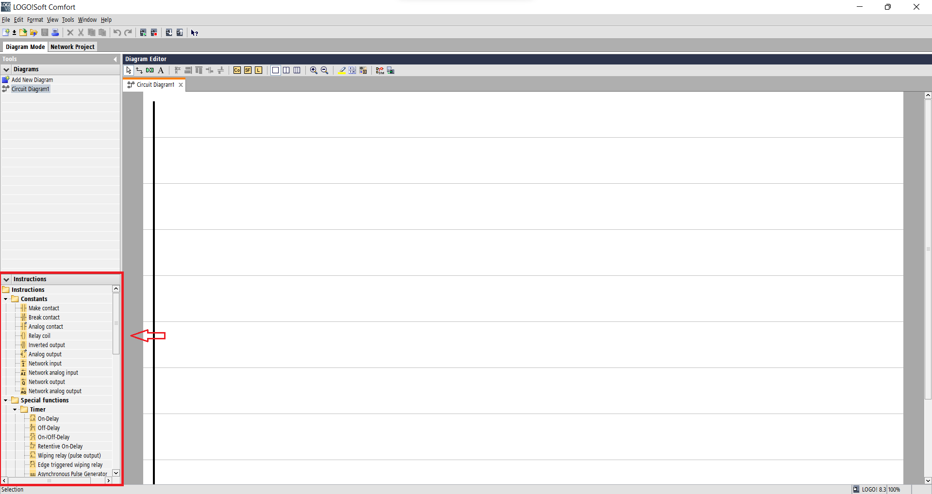
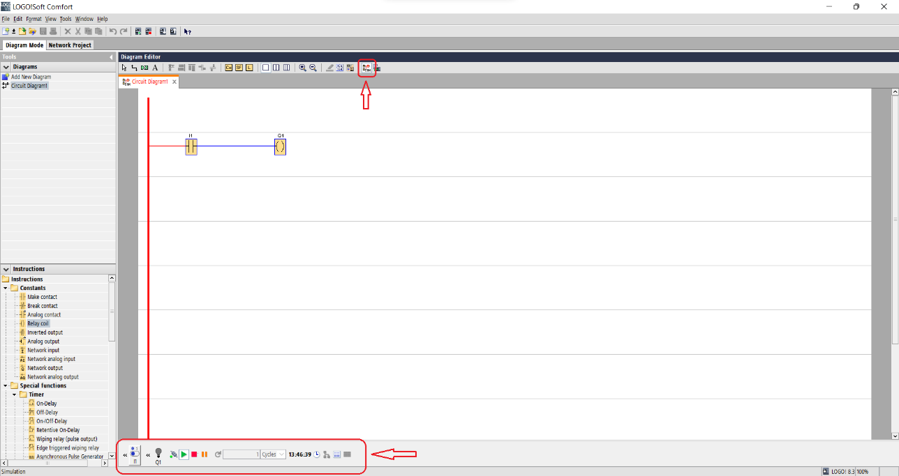
- Start the LOGO! Soft Comfort software.
- Go to, “File” ----> “New” ----> “Ladder diagram (LAD)”. This will create a new programming environment. You can even select other programming languages.
- A screen titled “Diagram Editor” will appear. Here you can drag and drop the pre-set contacts from “Instructions” for programming.
- Once finished programming select “SIM” from “Programming toolbar”, then from the bottom of the screen you can control the inputs and observe subsequent changes in output.
Basics for Programming
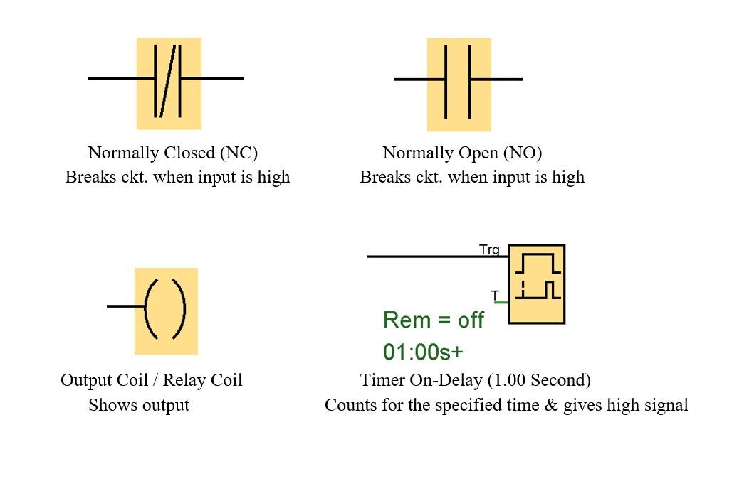
To program in any language, its functions and features need to be understood. In PLC programming, elements are used. These elements depict features. The following elements are some of the basic programming blocks:
- Normally closed
- Normally open
- Output / Relay coil
- Timer
Sample Program1
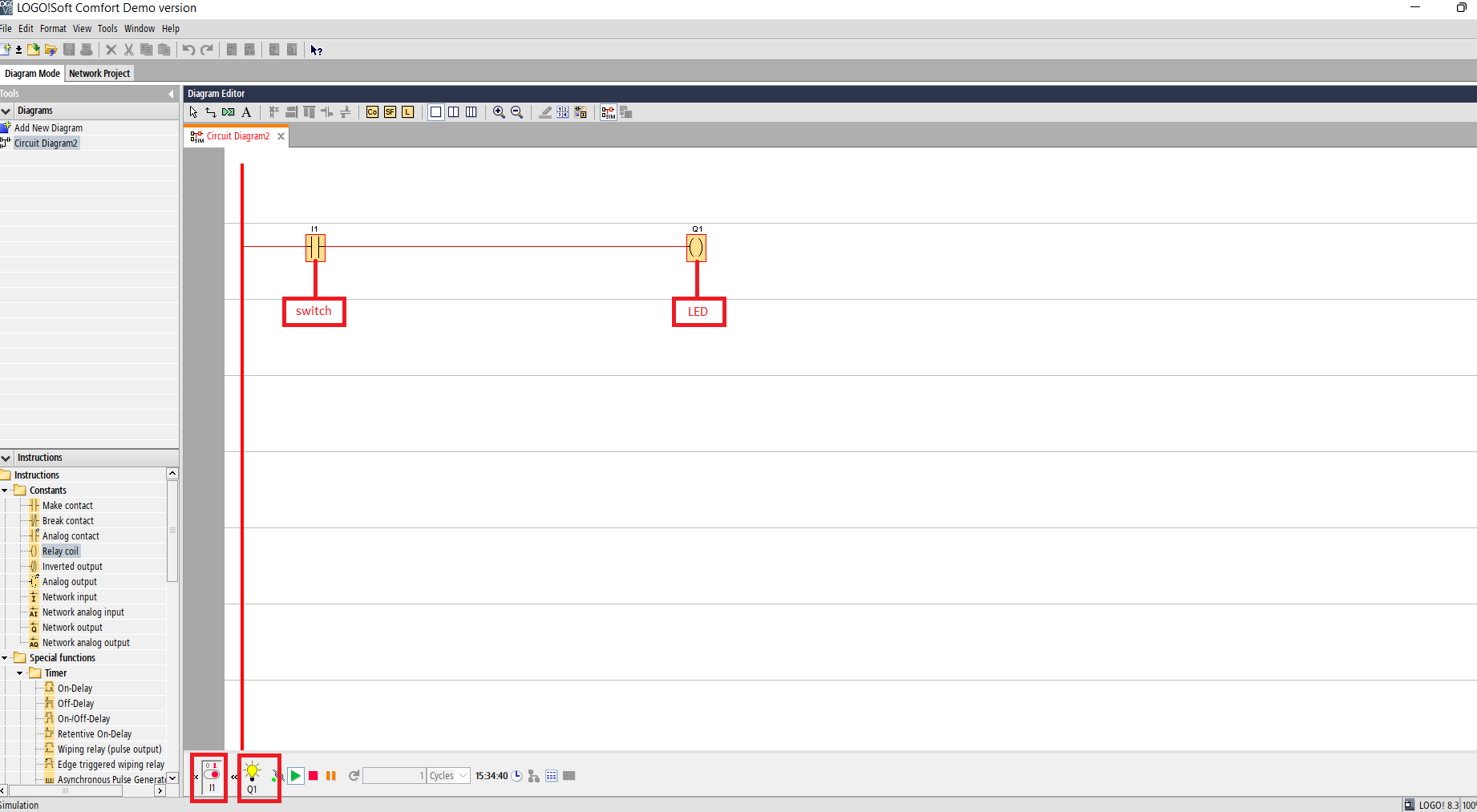
Q. Turn ON and OFF LED using switch.
Solution:
- Take a switch I1(make contact)---> Instructions--->Constants.
- Take LED Q1(relay coil)--->Instructions--->Constants.
Sample Pogram2
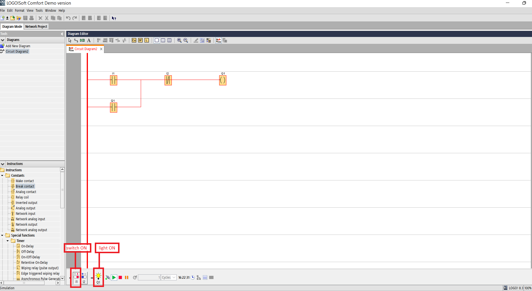
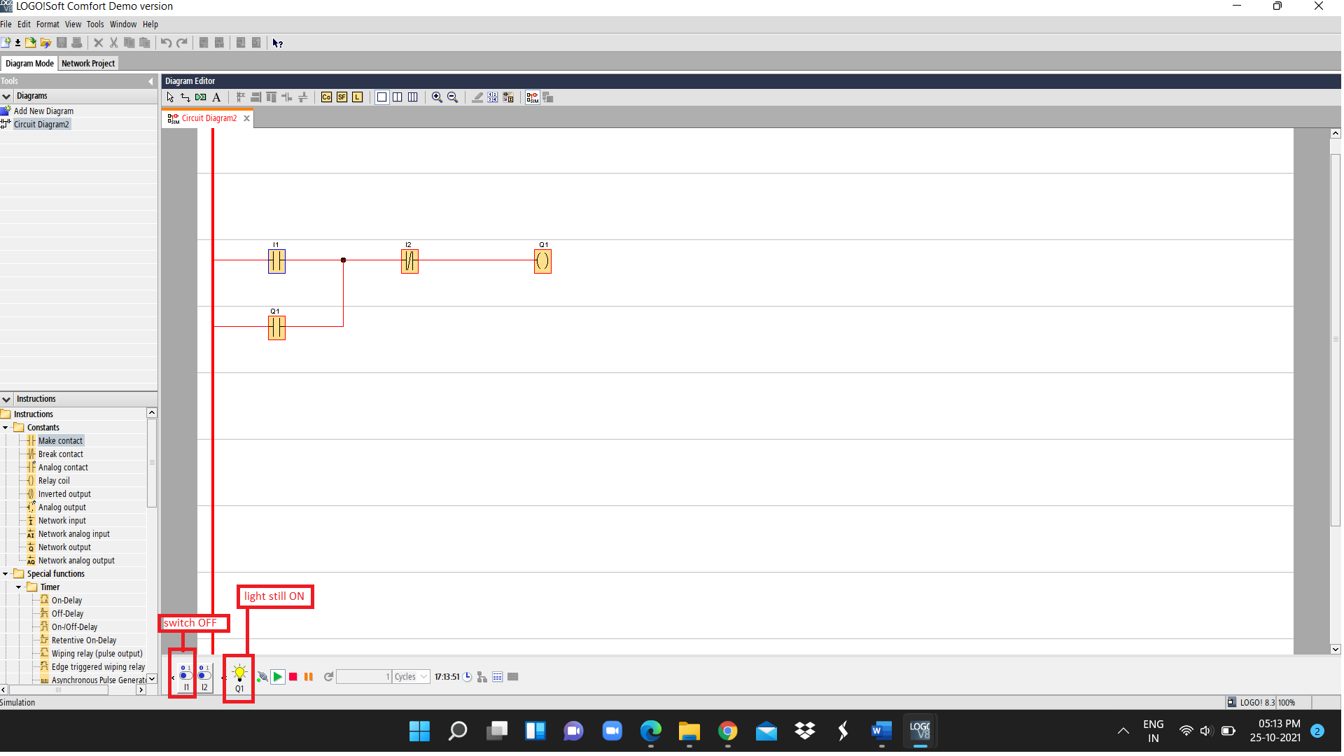
Q. Turn ON light using a switch. The light should remain ON even after the switch is turned OFF. You can take 2nd switch to off the light.
Solution:
- Take a switch I1(make contact) to turn ON the light.
- In series to switch I1 take I2(break contact) for fully shutting off the lights.
- Add a light Q1(relay coil) in series as shown in the image.
- For the light to remain ON even after the switch I1 is turned OFF you have to add make contact of relay coil Q1 in parallel to I1.
- As shown in the second image the light remains ON even after the switch I1 is made OFF.
Sample Program3
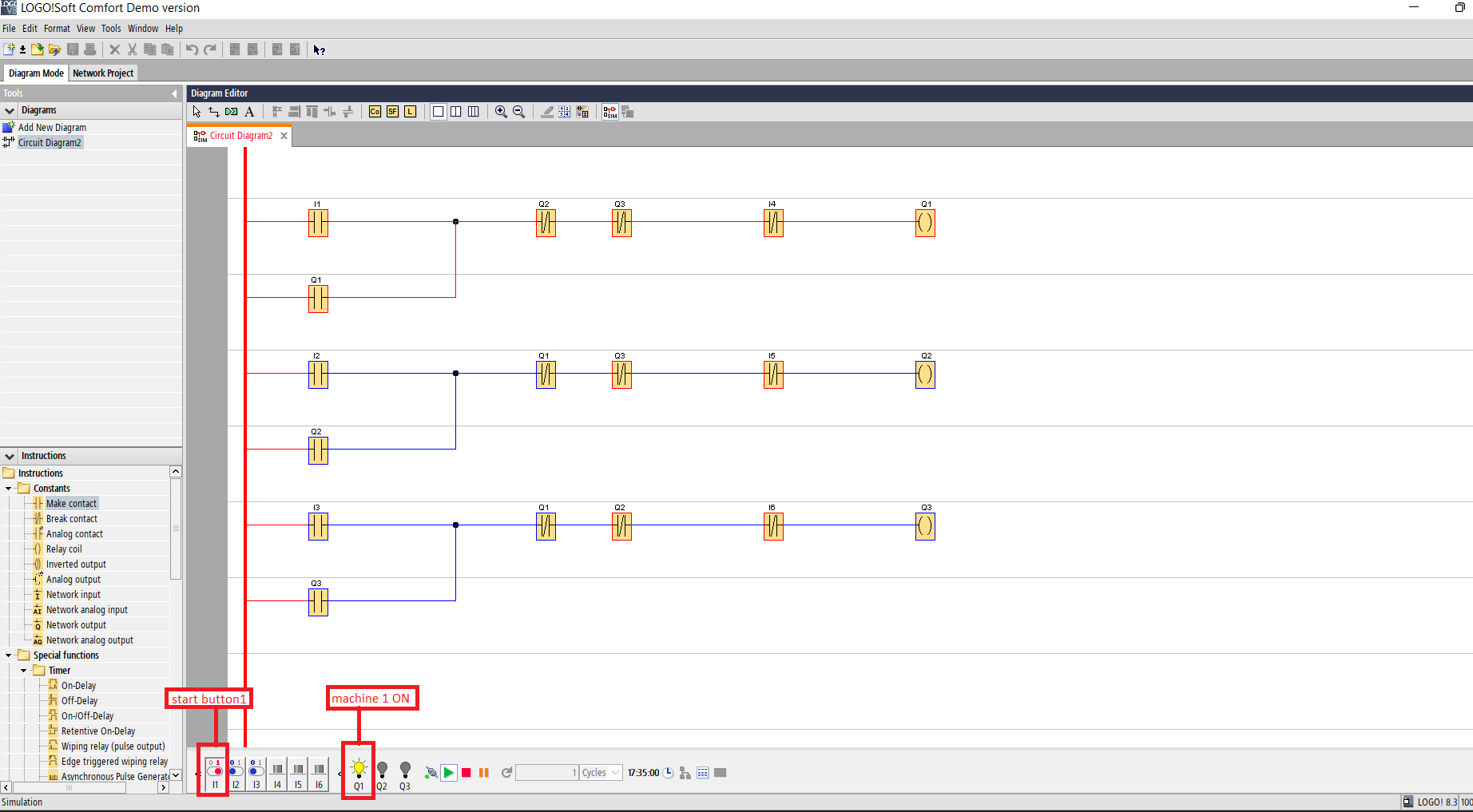
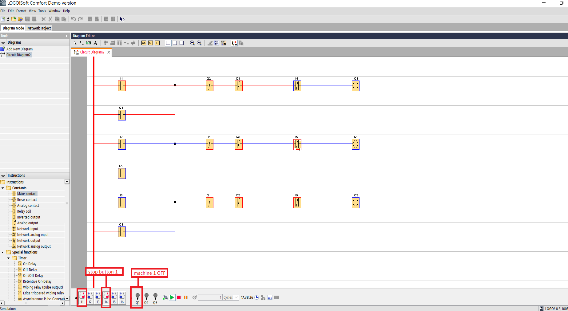
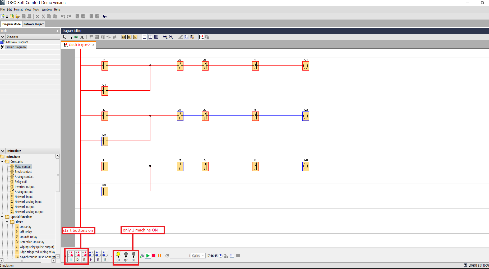
Q. There are 3 machines in a machine shop. Each machine has its own start and stop push buttons. The condition is that only one machine should run at a time. When one machine is in ON state the other two should remain in OFF state.
Solution:
- Take 3 start buttons(make contact) I1,I2,I3 to turn ON the 3 machines individually.
- Take 3 machines(relay coil) i.e. Q1,Q2,Q3 as shown in the image.
- Take 3 stop buttons(break contact) I4,I5,I6 to turn OFF the corresponding machines.
- As we are using push buttons we have to latch the circuit. Take 3 make contacts(Q1,Q2,Q3)in parallel to the corresponding start push buttons.
- As per the condition, only one machine should run at a time. The other machines should remain in off state when one of the machine is in working state. So we have to take break contacts of the other two machines in series with the machine that is in on state. As shown in the figure.
- As shown in the first image machine1 starts when start button1 is turned ON.
- As shown in the second image machine stops when the stop button is pressed.
- We can see in the third image that only one machine is ON at a time. The other machines remain off even after supply is given as one machine is in ON state.
Sample Program 4
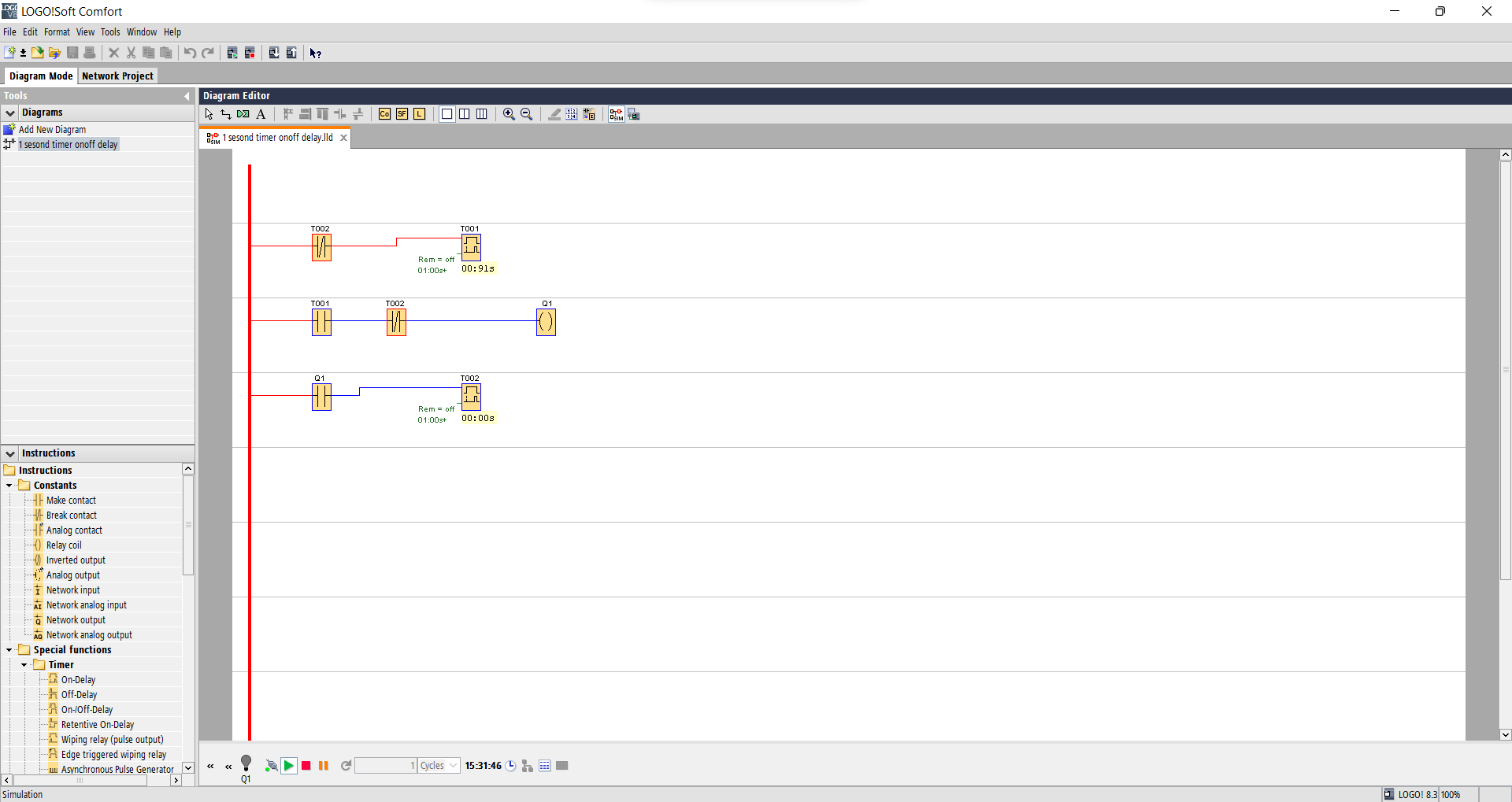
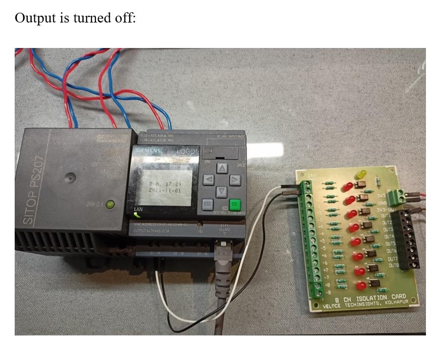
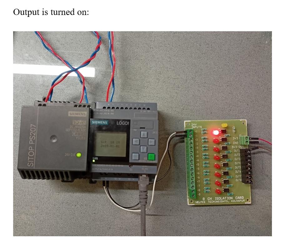
We will try this program using actual PLC. The connection that should be done in the software is as shown in the image. To change the time settings change the properties of the timer. The properties of the timer can be changed by double clicking the programming block.
Q. To turn the output (led) on-off for a period of 1 second.
Solution:
1. When the circuit it switched on, the timer T1 starts. T1 is connected in series with NC of timer T2
2. It runs for 1 second and for the entire duration keeps the output turned on.
3. This output activates the second timer T2 for a set duration of 1 second.
4. After the period of 1 second the cycle repeats itself.
Physical Connections
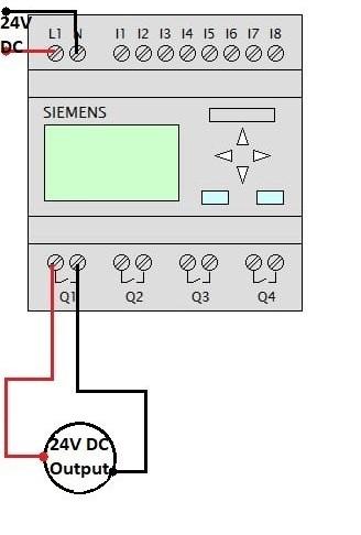
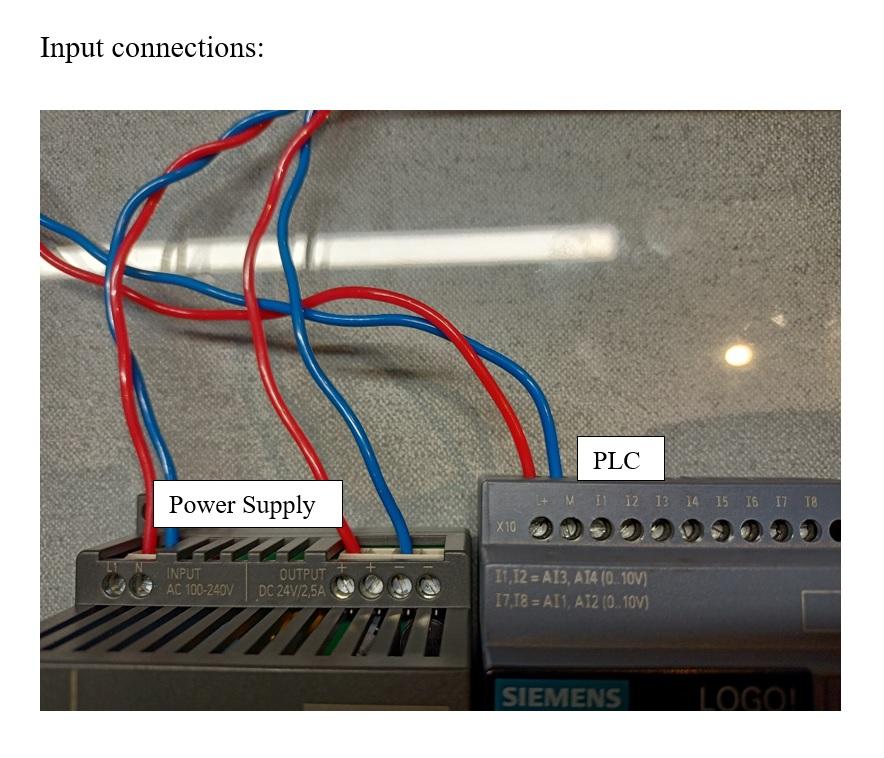
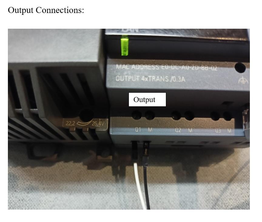
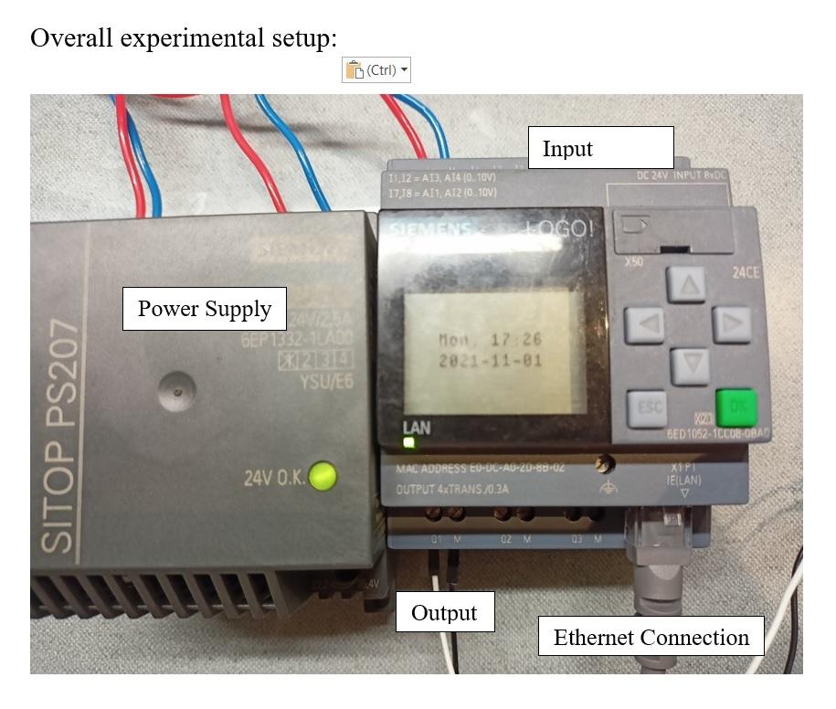
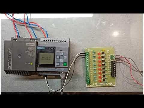
Circuit Diagram is shown in the first image. Input and output connections are also shown in the image. The overall set up after connection of input, output, power supply and ethernet connection is as shown in the image. Make sure that the physical connection are made properly, as the current and voltages level are high, wrong connections might damage your equipment
Conclusion
Here, I have tried to go into depth and explained the procedure step wise, please get back to me if the procedure gets unclear at any point. Now that you know about the registration, installation, configuration and basic programming of Siemens LOGO! in the next article we will further dive into details on it. Till then keep learning, keep growing….!!!
(This article is performed and documented by Trainee Interns: Punyokti Patil and Chaitanya Naik at Aerobotix Techsolutions in collaboration with Veloce Techinsights.