Getting Into World of PLC Part - I
by Aerobot09 in Circuits > Electronics
1251 Views, 6 Favorites, 0 Comments
Getting Into World of PLC Part - I
Hello there…!!!How are you doing? Hope you all are doing well. I guess all of you have enjoyed my previous instructable “When ESP8266 Meets NodeMCU”. Now I have come up with something new...!! Me and one of my colleagues are working on Siemens PLC and then we thought of sharing our experience. So here we go, let’s see about PLC (Programmable logic controller). Now you might be wondering how to directly learn about Siemens PLC without having any basic idea….don’t worry we will guide you from the very basic.
What Is PLC?
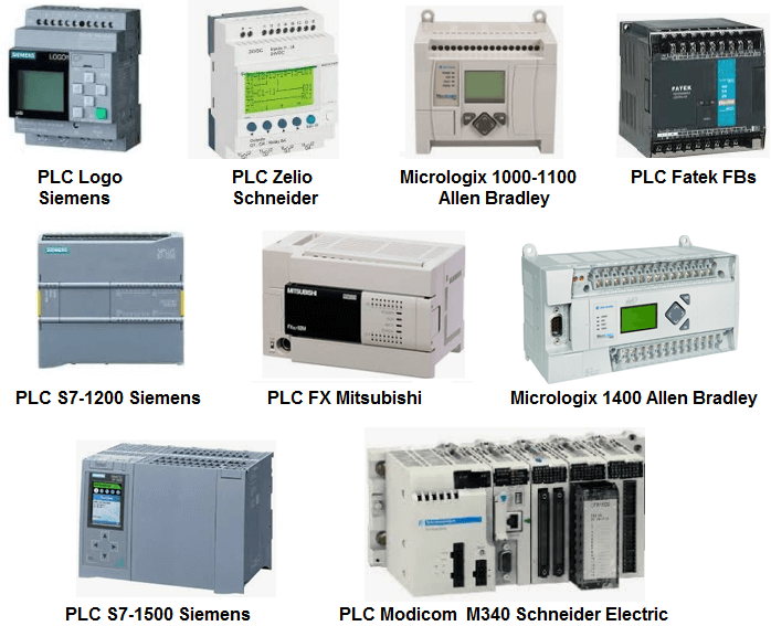
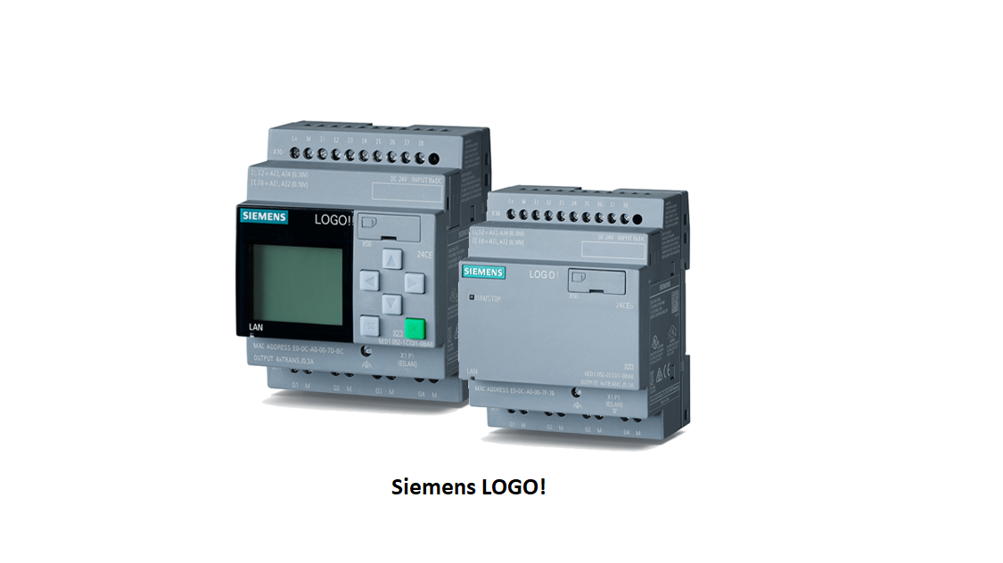
PLC stands for “Programmable Logic Controller”. A programmable logic controller (PLC) is a digital computer used for automation of electromechanical processes such as control of machinery in factories. As you can see in the image there are various types of PLC’s available in market out of which we are going to learn Siemens LOGO!
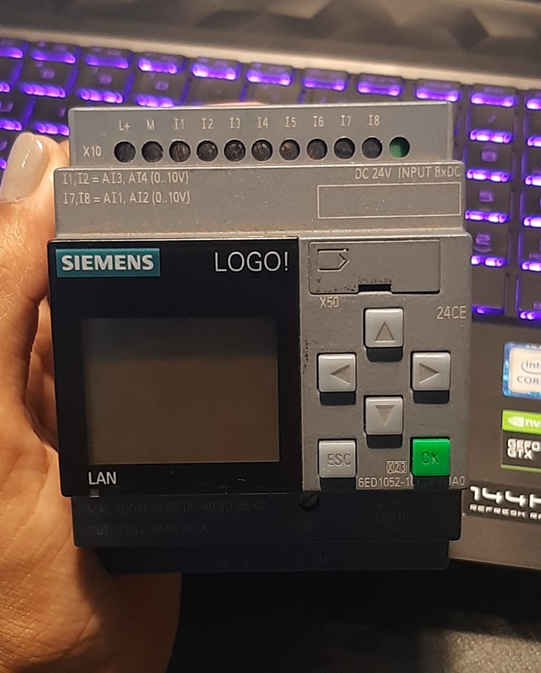
PLC is programmed interface between input sensors and output devices. PLC consist of different input elements like sensors, buttons, switches and final control/output elements like solenoid, control valves, actuators, drivers, etc. PLC is the combination of digital logic elements that are designed to take logical decisions and thereby provide outputs. As shown in the image Siemens LOGO PLC looks something like this.
Why PLC?
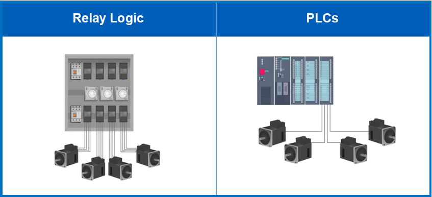
In early days before 1960’s control and automation tasks in industries were carried out via banks of relays. Each relay controller had inputs and outputs based on physical wiring. The old bank of relays was big in size and very complex. To change the operation, the physical wiring had to be changed which was very complex. Also faults finding was difficult and very time-consuming. To overcome the difficulties faced with relays, PLC was invented. It was introduced to meet the needs of the automotive manufacturing industries i.e., to provide flexible, rugged, and easily programmable controllers and as a replacement for relay systems. Now, they have been widely used in a variety of industries because they’re fast, easy to operate, and are easy to program. As compared to Relay systems, PLC units are more reliable, compact and required less maintenance.
Below is a differentiation between relay and PLC:
Relay
1. Has more wiring
2. Changes are difficult to make
3. Requires more power
4. Requires more maintenance
5. Difficult to expand
PLC
1. Has less wiring
2. Changes are easy to make
3. Requires less power
4. Requires less maintenance
5. Easy to expand
Considering all the factors above we can easily determine that PLC has successfully replaced Relays and is commonly used in many industries nowadays.
PLC Architecture
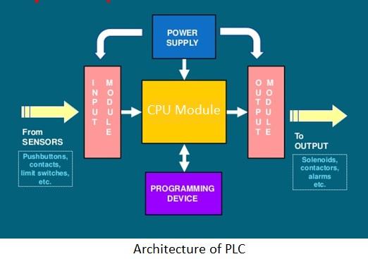
PLC architecture is the overall design of the PLC system. All PLC have four basic and essential components, combination of all these components is considered as a full system. As you can see in the image Power supply, CPU Module, input/output modules and programming device are the four main components of PLC. Further we will see the components in detail.
1.CPU module: Firstly, processing of the data occurs in the CPU of PLC and then it executes the control program that is stored in memory to send output signals.
2.Power supply module: It is a crucial module in providing power to the attached components of PLC and attached devices. It receives AC power and converts it into DC power.
3.Programming device: Various operations and logic need to be controlled without which a PLC is dysfunctional. Programs of various PLC can be written through their respective software.
4.I/O modules: They send and receive data to and from external devices. These modules can either be in digital form or analog form.
PLC Process Pipeline
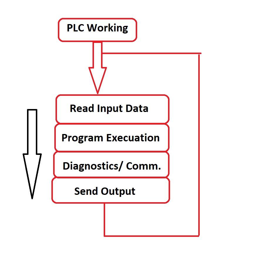
Components of PLC architecture work in coherence to ease the task of industrial automation. PLC captures data from the plant floor by monitoring inputs from the machines and devices that it is connected to. The CPU thereafter applies logic to the data, based on the input state. Logic is nothing but the user-created program representing the desired functioning for the process or task. The CPU after processing sends outputs or commands to the machines and devices connected to it.
CPU Module of PLC
CPU module has a central processor, memory, and other integrated circuits. It is known as the heart of PLC. ROM memory includes an operating system, application programs, and drivers. RAM (Random Access Memory) is used to store programs and data information.
1. Central Processor: It controls and supervises all operations within PLC through defined programming.
2. Memory: The total memory system in a PLC consists of two different memories Random Access Memory (RAM) and Read-Only Memory (ROM). These are present in every CPU module of PLC and are used to store temporary and permanent information respectively. Reading and writing operations occur in RAM while writing cannot be performed in ROM. The program controlling PLC are stored in ROM.
PLC Power Supply
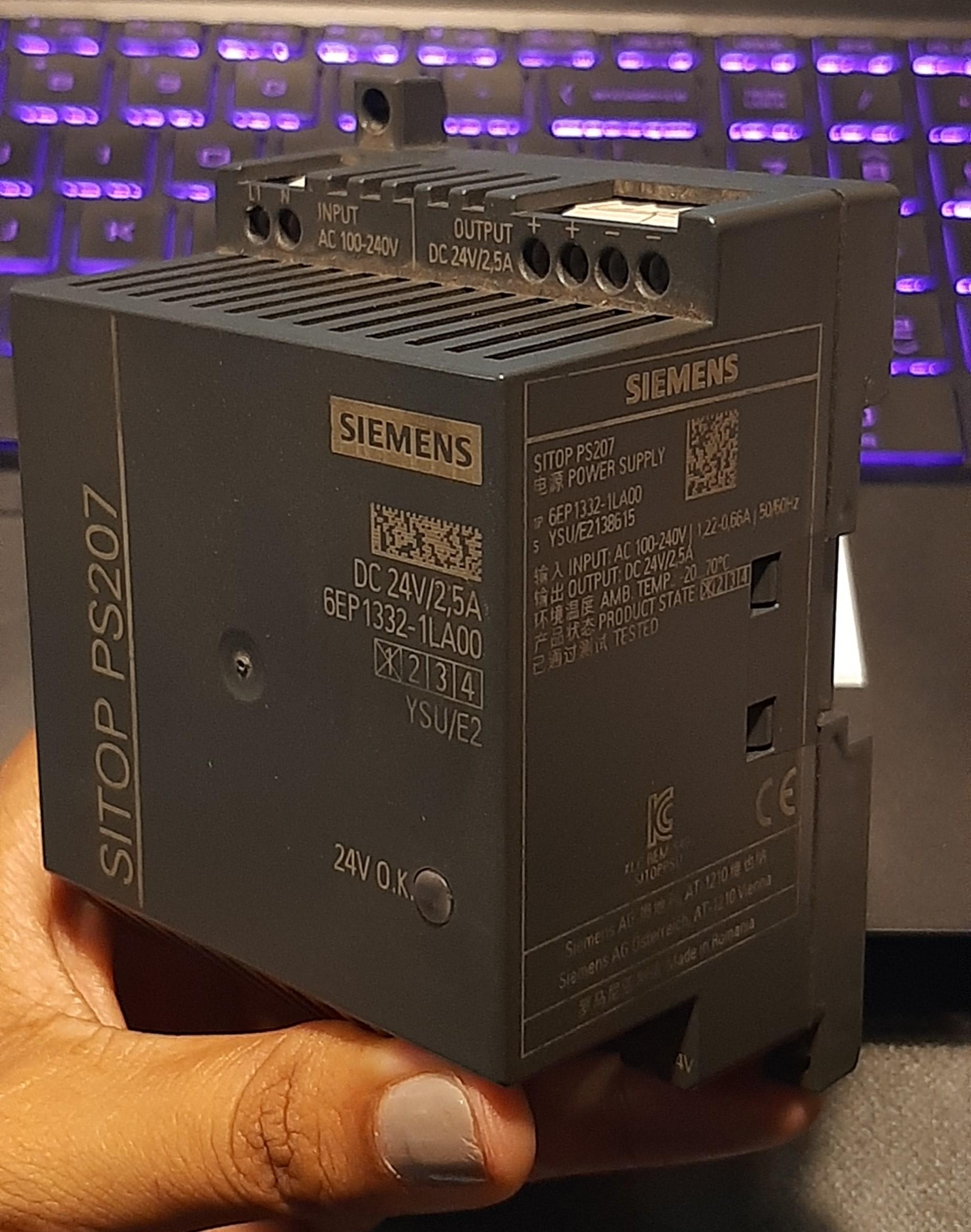
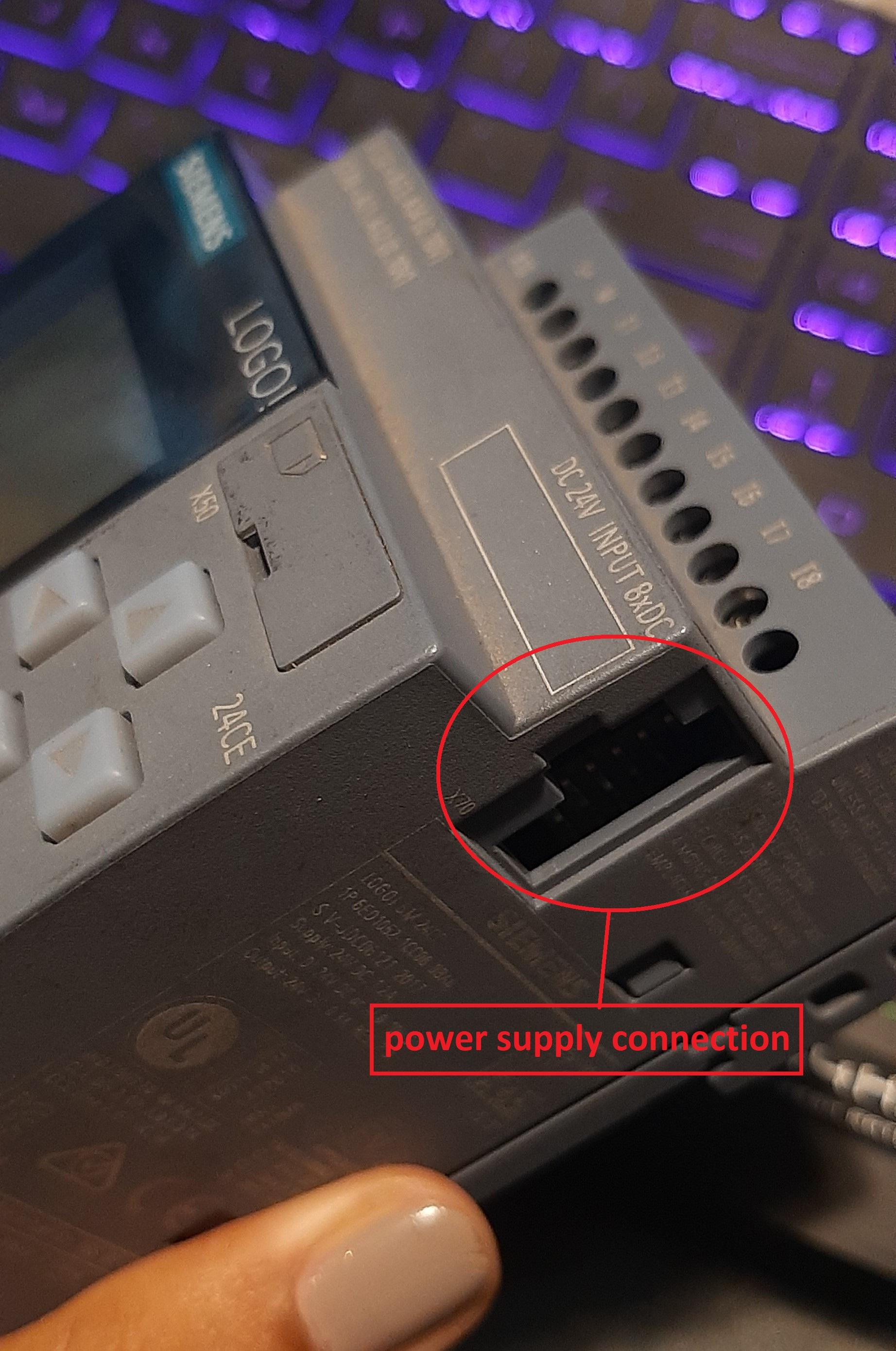
Power supply is an important part of PLC. It provides the voltage required to run the primary PLC components. PLC works on 24V DC while the devices attached to it require higher AC voltages, thus a power supply is necessary for conversion of voltages. This is the power supply of Siemens LOGO. Power supply should be given to PLC as shown in the image.
PLC I/O Modules
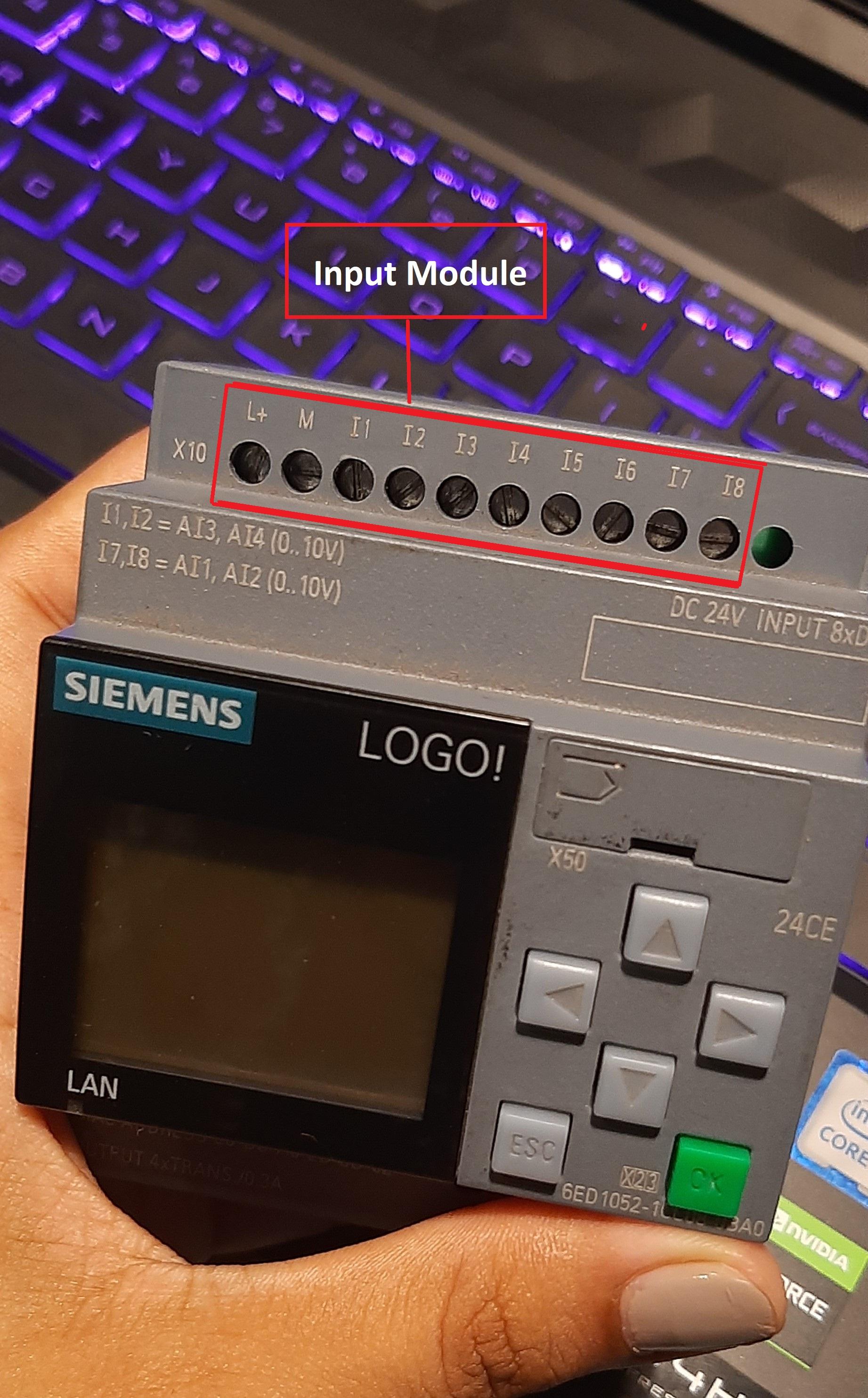
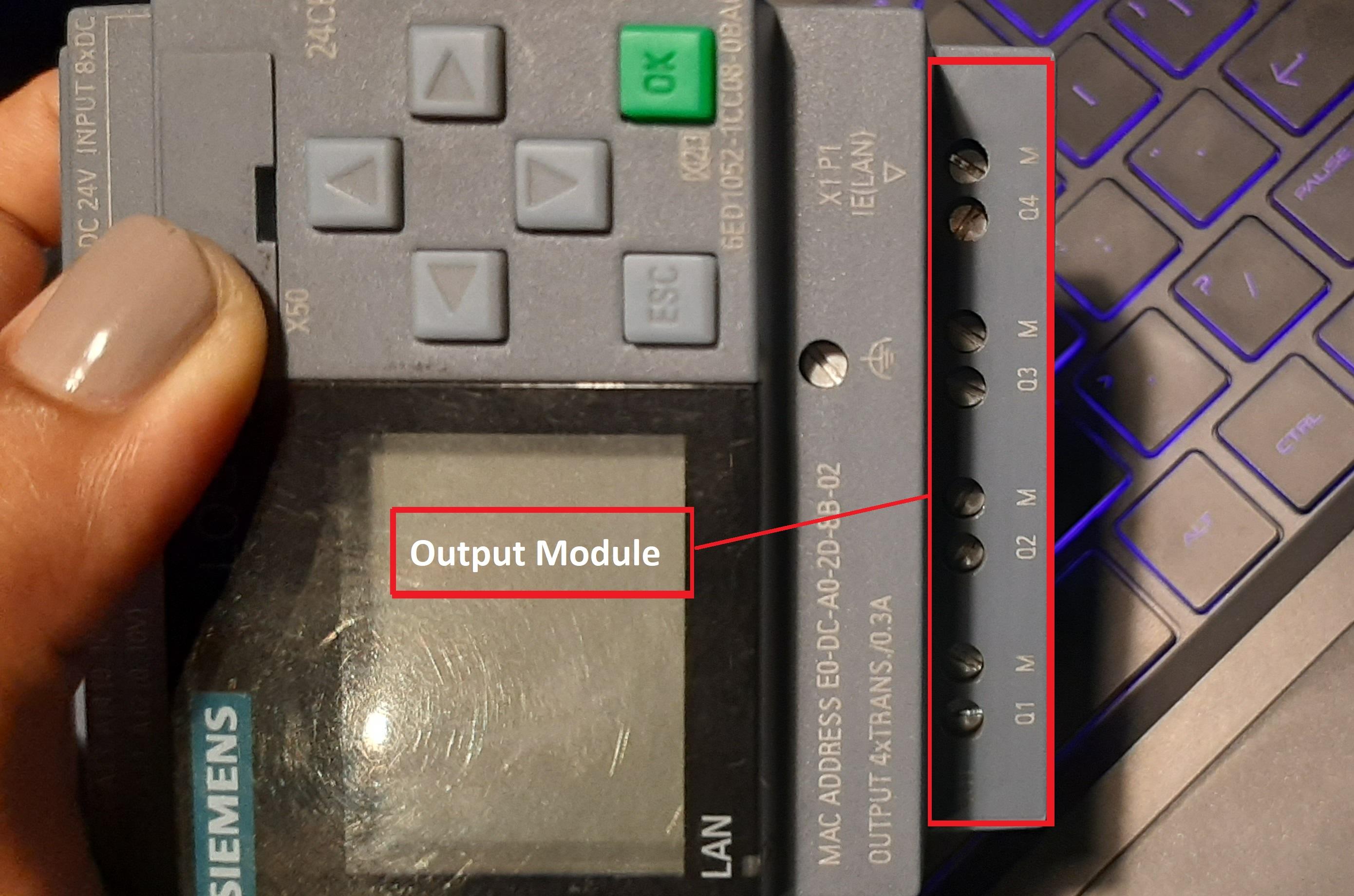
The I/O Modules act as receivers and transmitter of data. Input modules receive signals from sensors or switches and transfer the values to the CPU while Output modules receive signals from CPU and transfer those to the connected devices. These input/output modules can be either in digital or analog forms.
Advantages:
o Wide range of control application
o It has small physical size
o Troubleshooting is far easier
o Reliable in performing operation
o High scan time
Disadvantages:
o There are limitations for working of PLC under high temperature.
o To maximize the performance additional modules should be added.
o Only closed loop architecture is offered by PLC manufacturers- every manufacturer has different software for operation.
PLC Programming Languages
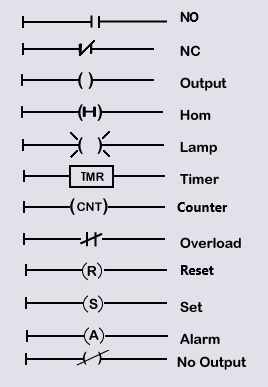
There are 5 different types PLC Programming Languages:
1. Ladder Diagram (LD):
It is the original programming language for PLC. Here programming can be done via relay logic symbols. Ladder diagram is the simplest form of PLC programming. It is commonly called as “relay logic”. Although all of these PLC programming languages can be used to program a PLC, Ladder diagram is typically preferred over all other languages. Ladder symbols are as shown in the image.
2. Sequential Function Charts (SFC):
As the name suggests, the program execution is in sequence in the form of a flowchart. “Steps” and “Transition” are 2 important elements of programming. Steps are the functional blocks in programs while transitions are used to transit from one step to another.
3. Function Block Diagram (FBD):
The function to be carried out is programmed inside of a box which is then connected within connection lines. This allows easy representation and error correction of programs.
4. Structured Text (ST):
Programming of PLC using this language is similar to that of C. It is a high-level language that can execute the desired task using functions and algorithms.
5. Instruction List (IL):
It resembles Assembly language, here each line of the program specifies instructions, conditions, and outcomes of the execution.
Conclusion
Here we have studied the basics of PLC.I guess you all have got the basic idea of what actually PLC is. This is the first part of Getting into world of PLC, in the second part we will see Siemens LOGO in detail . Stay connected for the next part, where we will study about registration, downloading, installation and set up of the Siemens LOGO! Comfort software. I will also try to cover an example for better understanding purpose. Hopefully I will very soon upload the part 2. Till then keep learning, keep growing..!!
(This article is performed and documented by Punyokti Patil- Trainee Intern at Aerobotix Techsolutions and Chaitanya Naik- Trainee Intern at Aerobotix Techsolutions).