Get Started With ESP8266 (NodeMCU Lolin V3)
by MrSottong in Circuits > Arduino
54641 Views, 18 Favorites, 0 Comments
Get Started With ESP8266 (NodeMCU Lolin V3)
Component Required:
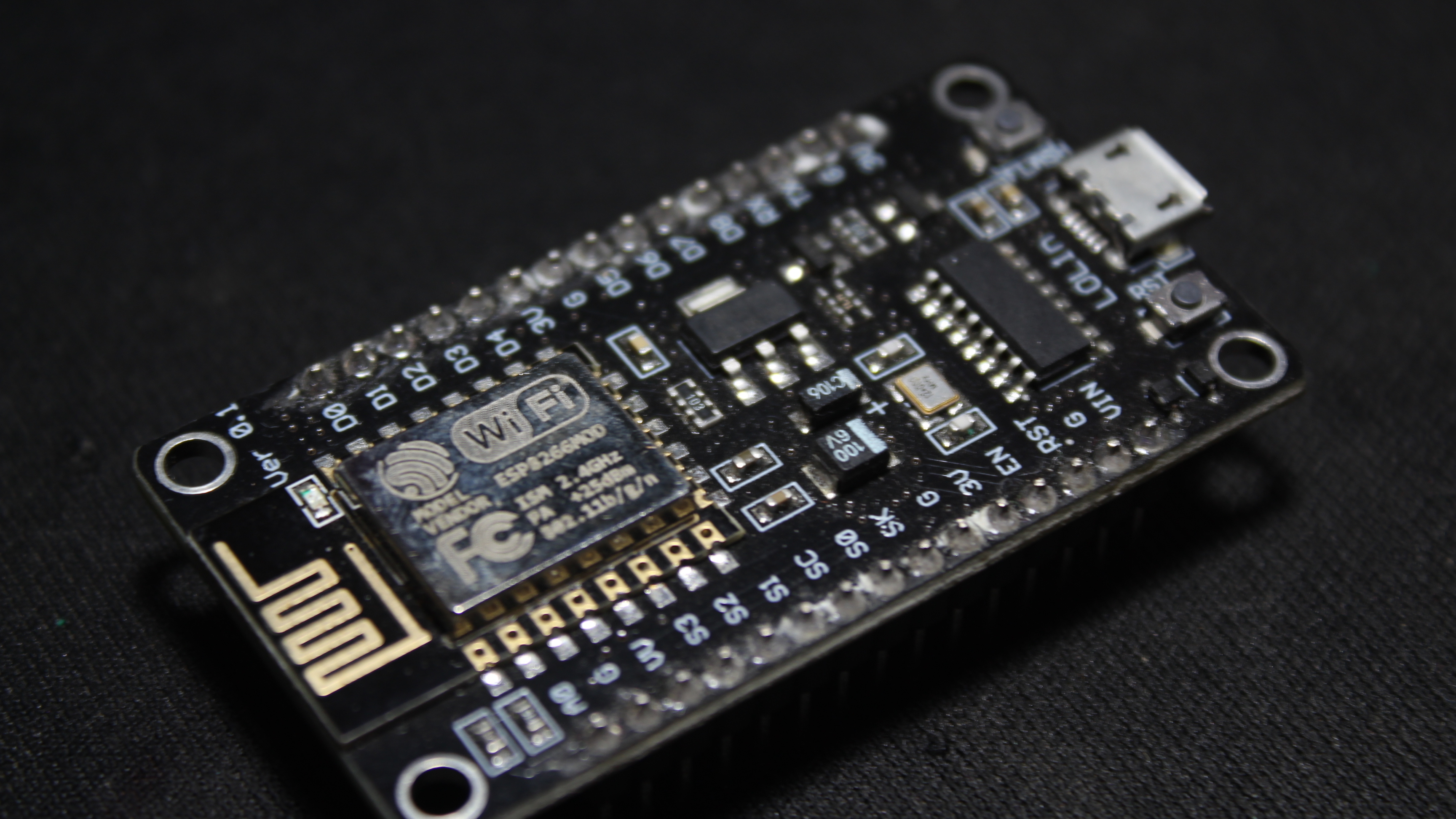
- ESP8266 (NodeMCU Lolin V3)
- Micro USB
- Arduino IDE
- Internet connection
NodeMCU lolin V3 Feature:
- Open-source
- Status LED
- MicroUSB port
- Interactive and Programmable
- Low cost
- ESP8266 with inbuilt wifi
- USB to UART converter
- GPIO pins
Add ESP8266 to Arduino IDE
this is a way to add the NodeMCU lolin V3 board to the Arduino IDE:
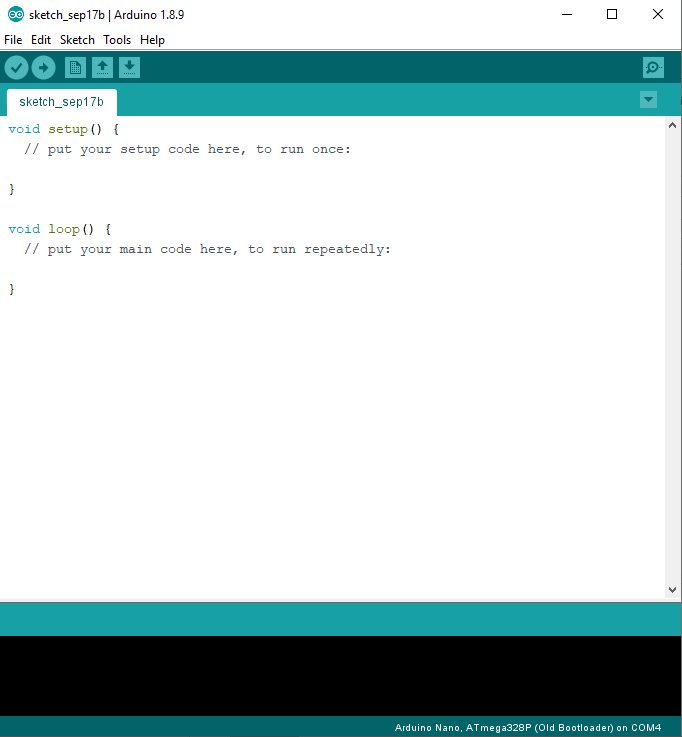
- Open Arduino IDE.
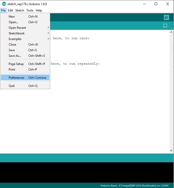
- Click File > Preference.
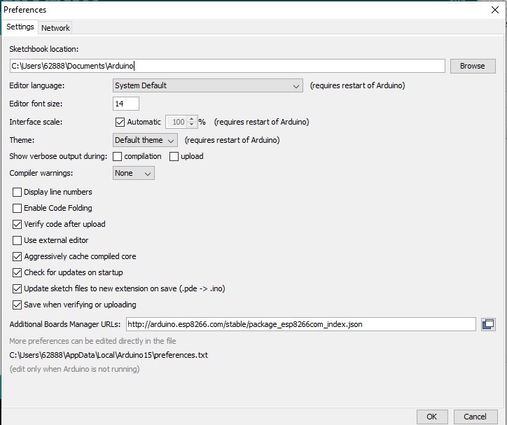
- Add This URL "http://arduino.esp8266.com/stable/package_esp8266com_index.json" to Additional Board Manager URLs.
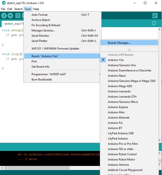
- Go to Tools > Board > Board Manager.
- Wait until the update is complete.
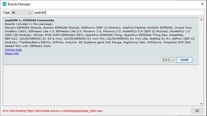
- Search esp8266 by ESP8266 Comunity, then install, wait until the installation is complete.
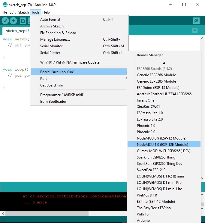
- After it finishes, Go to Tools > Board > NodeMCU 1.0 (ESP-12E Module).
Port on NodeMCU Lolin V3
To use a Port on NodeMCU, it is different from Arduino.
An example is the use of "pinMode ()"
To make Port D5 on Arduino as Output, the code will be like this:
pinMode(5, OUTPUT);
And to make the D5 port on NodeMCU lolin V3 as Outout, the code will be like this:
pinMode(D5, OUTPUT)
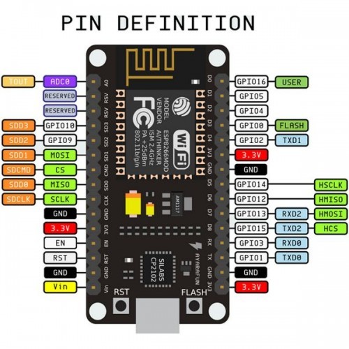
If you don't write the full port address when using NodeMCU lolin V3. What will be detected in the program is Port of ESP-12E which is in the Node.
See pictures for more details
Example Sketch
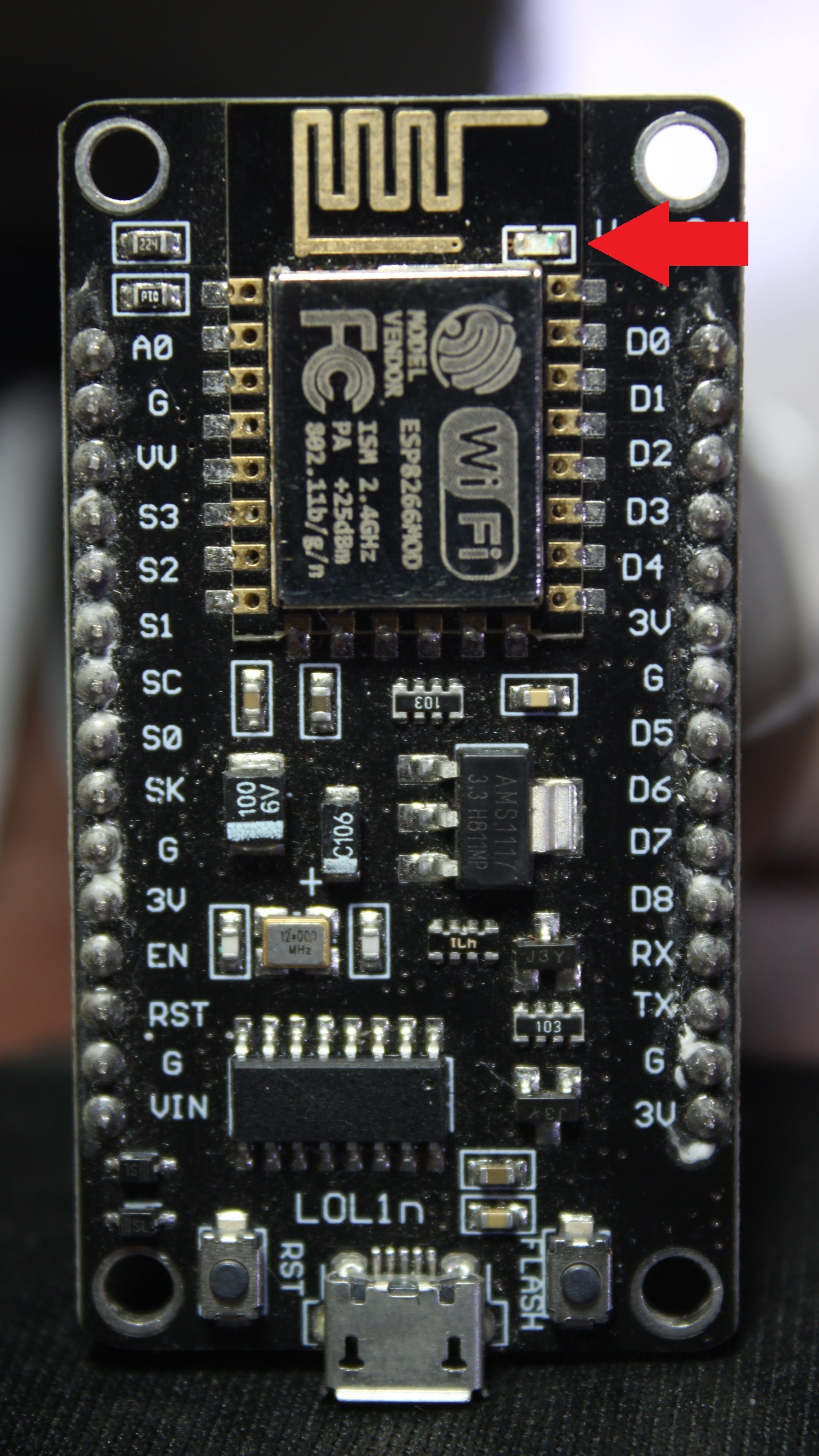
NodeMCU lolin V3 has LEDs installed on it. The led is connected to Port D4. I will use these LEDs for example sketch.
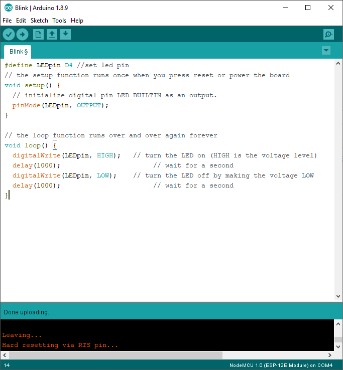
Example Sketch:
#define LEDpin D4   //set led pin
// the setup function runs once when you press reset or power the board
void setup() {
  // initialize digital pin LED_BUILTIN as an output.
  pinMode(LEDpin, OUTPUT);
}// the loop function runs over and over again forever
void loop() {
  digitalWrite(LEDpin, HIGH);   // turn the LED on (HIGH is the voltage level)
  delay(1000);                       // wait for a second
  digitalWrite(LEDpin, LOW);    // turn the LED off by making the voltage LOW
  delay(1000);                       // wait for a second
}
Based on the example sketch that I made. LEDs will flash once every second.