Gel Dispenser


Hi all
In this pandemic situation the care is necessary for that in this opportunity i present the functional and easy gel dispenser made in the program called "Autodesk Fusion 360" presented by me Fabian Mautino Penagos student in the university "San Martin de Porres" in Perú.
Lets started!!!!
Supplies
What do we need?
Not much to make this design!!!
First go to your computer and dowload the program "Autodesk Fusion 360" free and secure
Then relax, put on some music and let's get started.
Step 1: Dispenser First Side-Create Sketch
Let's start with the first face
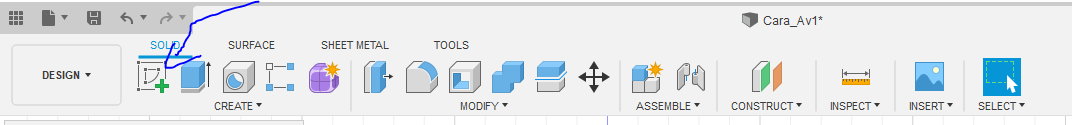
First go our application and press "Create Sketch" to begin the proyect
But first save it with the name you want
SELECTION

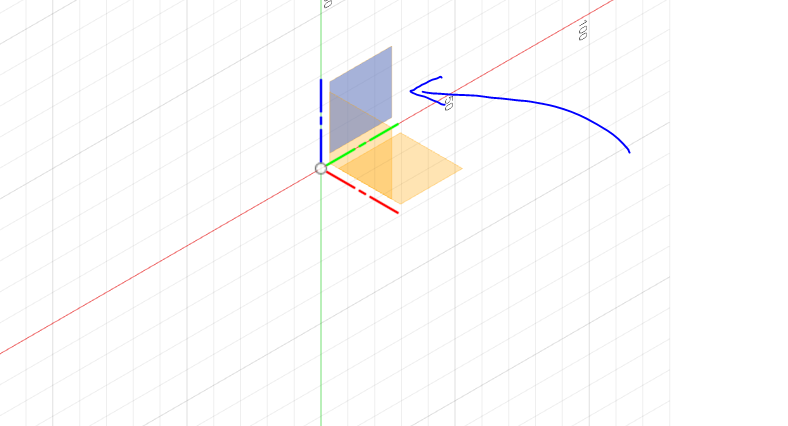
Now we choose the left side that would become X-Z, we click
The Structure-1


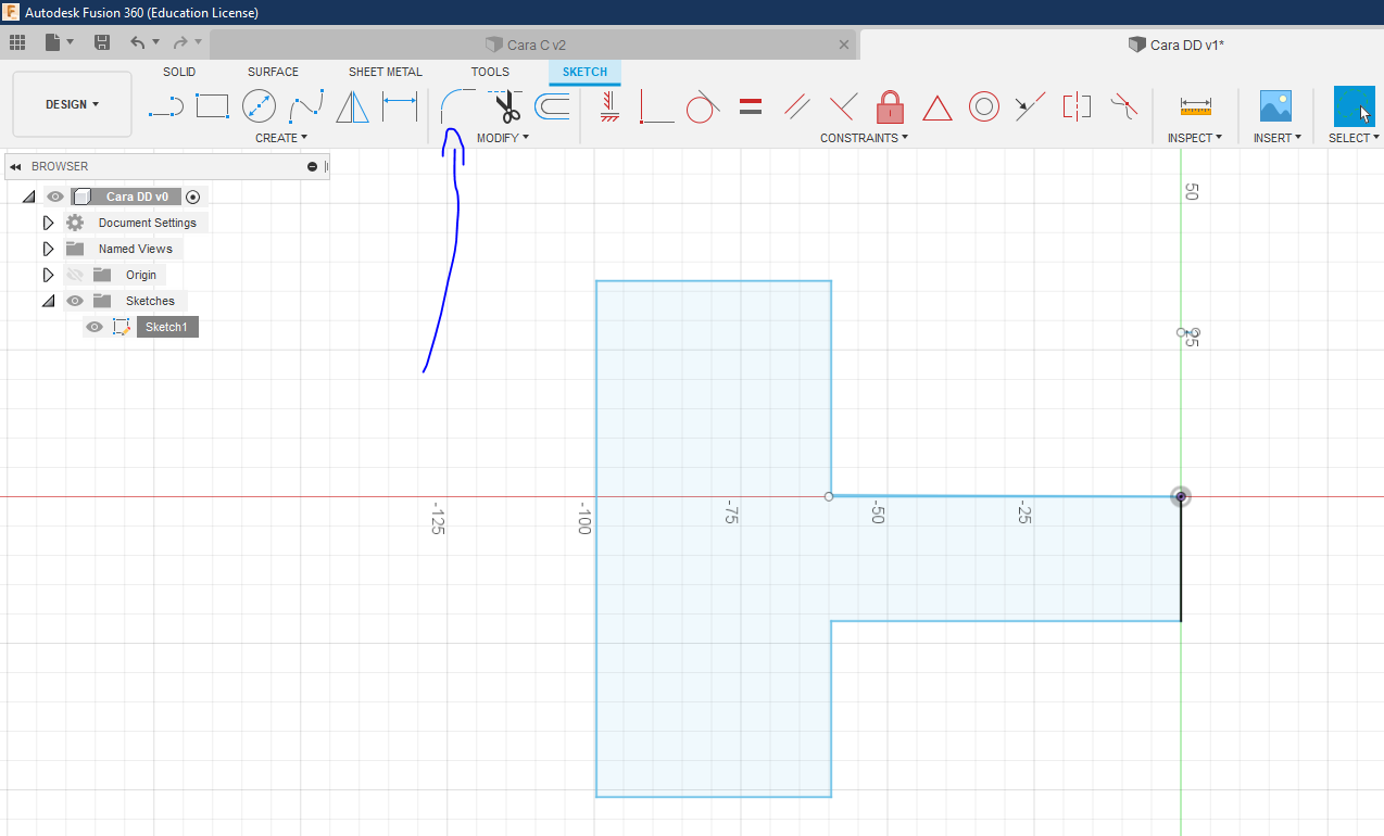
Go to solid section and select line
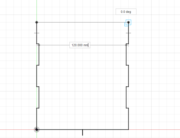
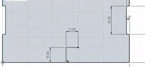
Then we place ourselves in the center of the whole and we click there
We can move the line to our liking but in this case we put 120 and put it down, then we only click and it will appear
Observation: Always work with click, when entering enter it will not be possible to complete
The Structure-2


After we have all the above we start, from the right another box will go up we put it to be 28 then we click it, after that another one will appear we put it up and it measures 3 and so on, seeing the sides and the times in the picture.
The Structure-3
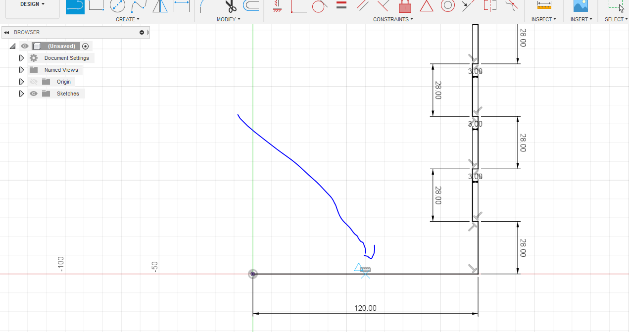
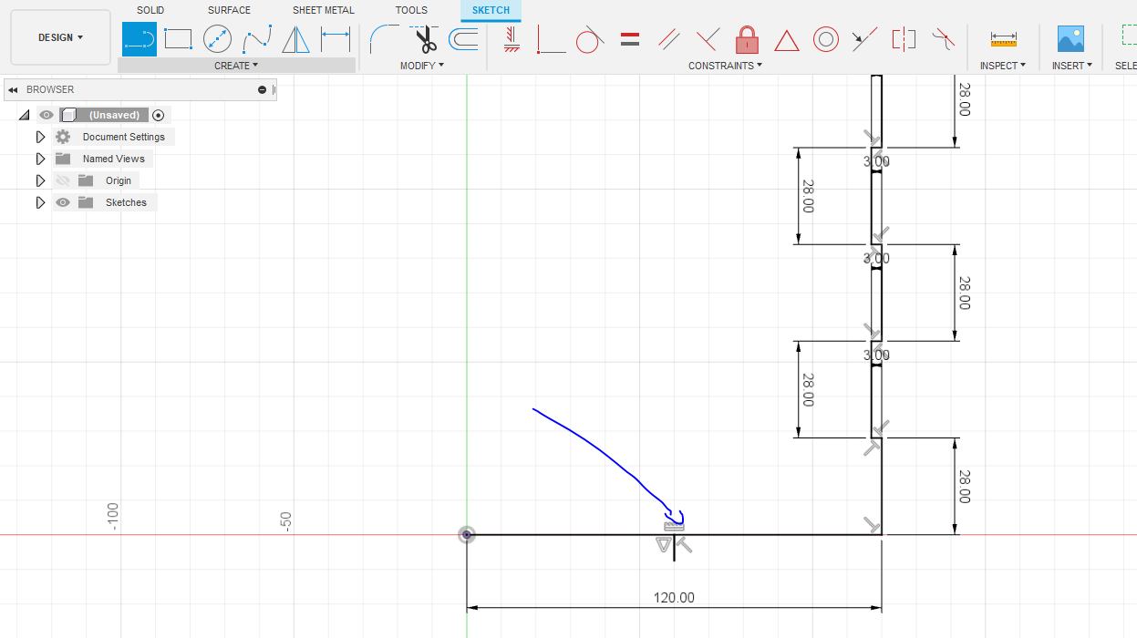


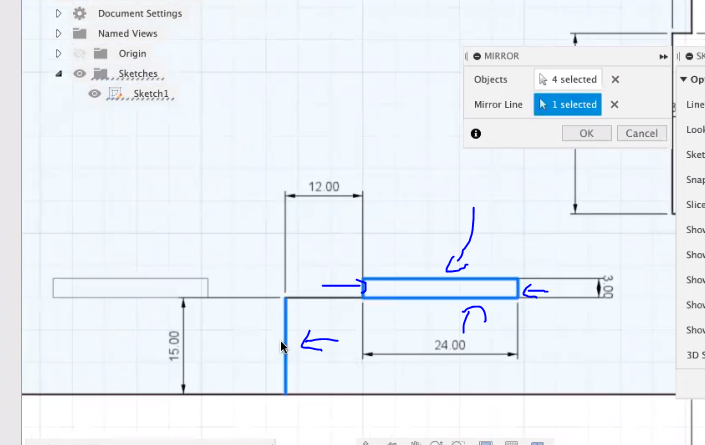
Since we have everything we go to the graph below and we go to the middle (to know which is a triangle will be seen) and we place a small line with the same function called line.
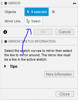
For the following we need to go to our panel on the right that if you do not see it, click on the 2 little arrows that will be seen on the right and remove the marks that can be seen in the photo.
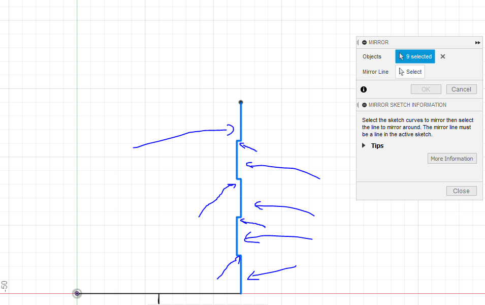
Then we locate create and select mirror, a panel will appear in this verification that is selected for "objects" and we select those seen in the photo and then select "mirror line" in the same panel and select the line that we did below, it will be something like this and we put in "okay" located in the panel.
Finally we only create a line that connects the missing.
The Structure-FINAL FIRST FACE
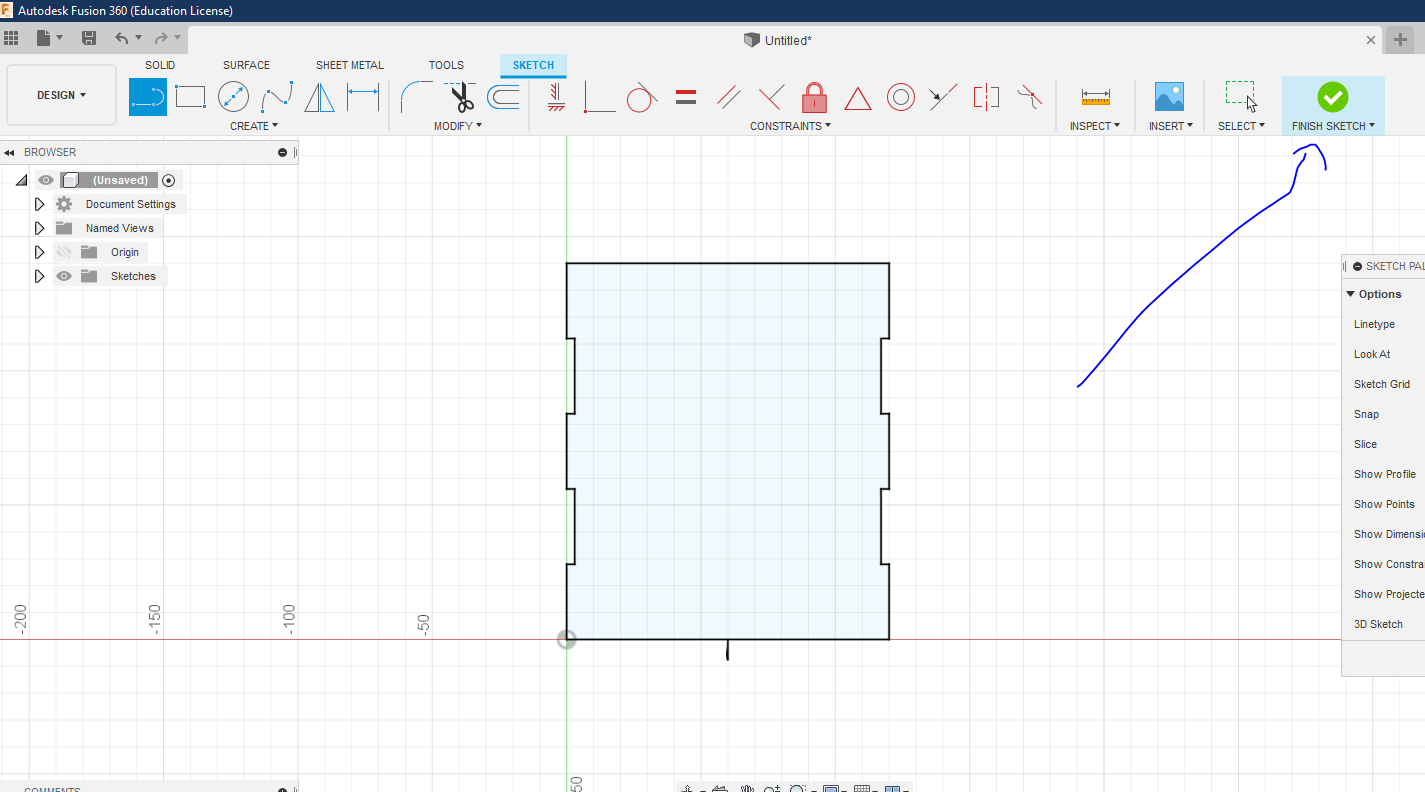
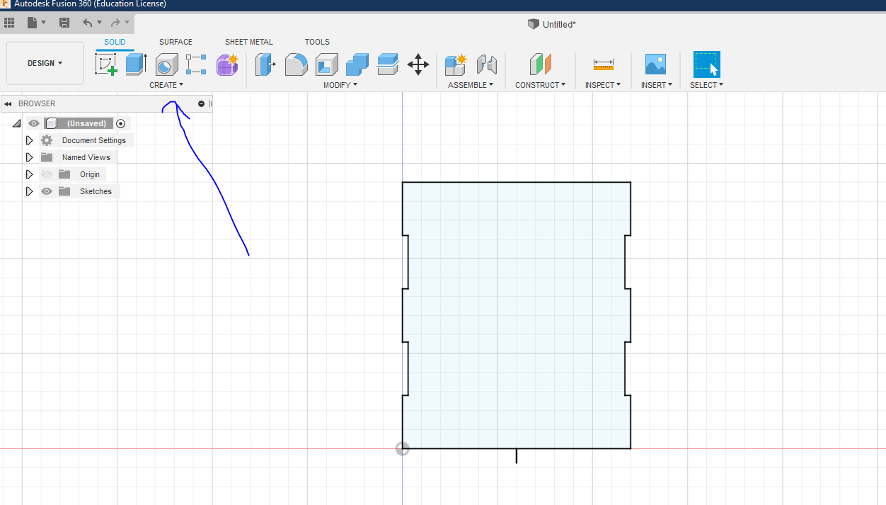


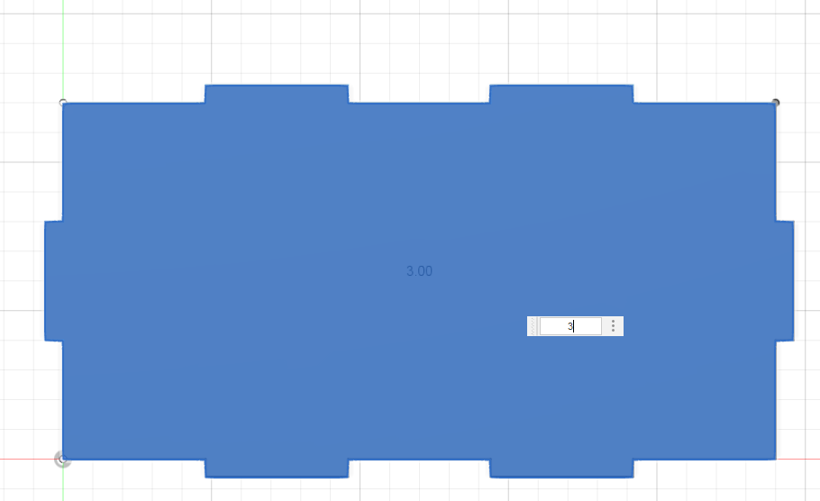
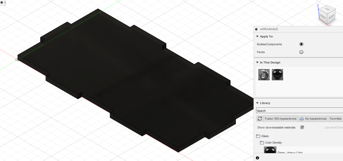
Having already all that part ready we put "finish sketch" and then go to "create" and select "extrude" to which we will put 3mm, to customize it we press "A" on our keyboard where a panel will appear in which we preferably choose the section of "glass" dragging the one that we choose to the form so that it is already placed
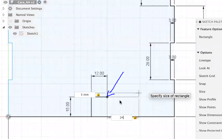
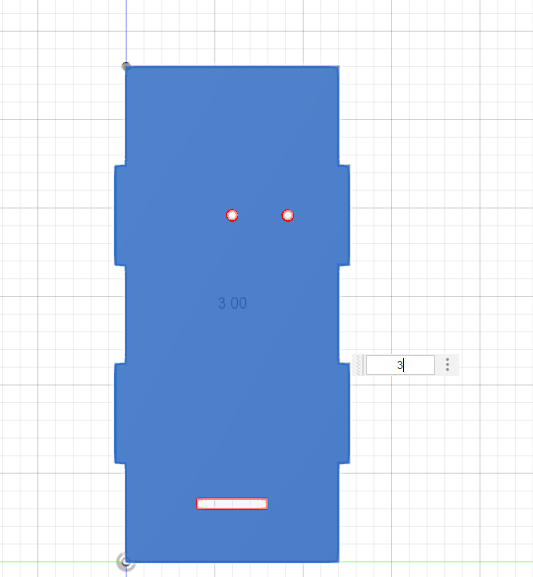
Finally we go to our left side and we will see a small panel where we will see a folder called "Sketches" which we select leaving Sketch 1 by right clicking there and putting edit sketch, we go to the center of everything as before using "Line" again with 15 for up and 12 right, then selecting the option "Point Rectangle" shown in the image, then selecting the last point on the right of 12 and making the rectangle with 3mm from above and going to the next with the "tab" key. "Putting 24mm there then we select the mirror option previously used and we only select what is highlighted in blue in the image when it appears we give the" escape "on the keyboard and we are erasing what we no longer need, we place" finish sketc "of new and last we go to the square that can be seen in the lower part and we press right click and we give "dit feature" where we select the 2 squares that we have, we give "okay" and we have all this ladder or done
This is how easy the first face step by step!
The Structure 2- Second Side or Face


Now that we are more familiar with the application we are going to do it a bit faster and easier with the following sides first starting with the second face or the second side.
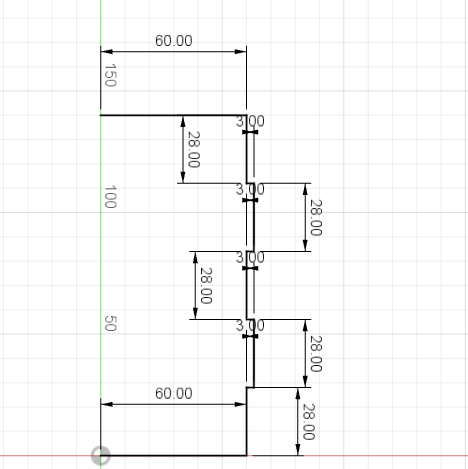
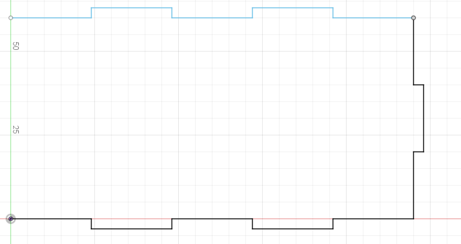
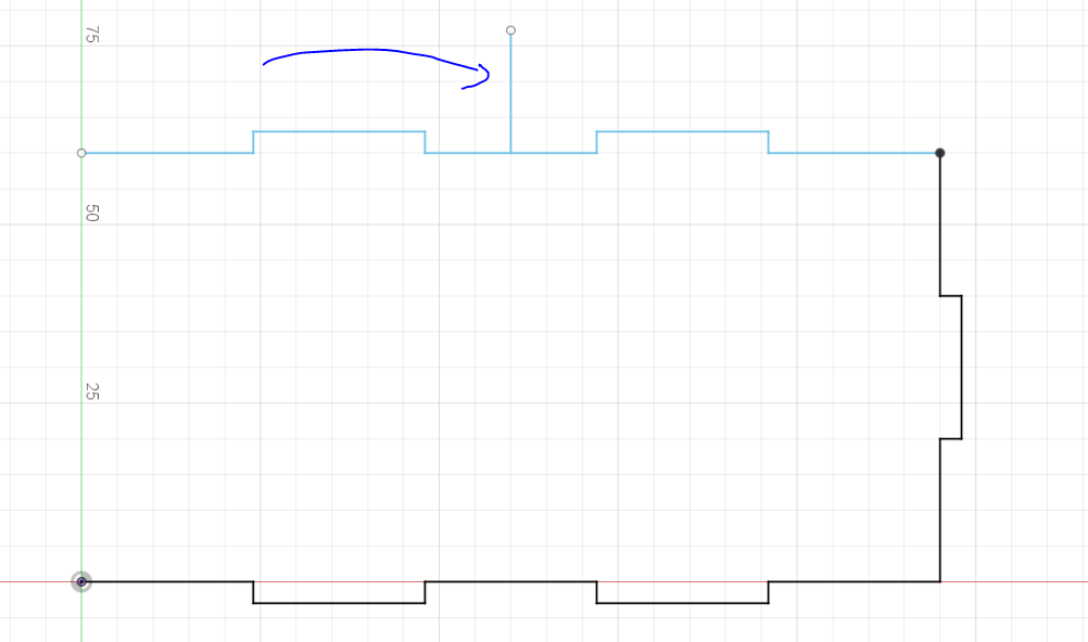
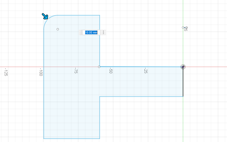
First we are going to create a sketch and then select the face indicated in the image again, we start from the center but now with 60mm, then putting a 28mm one to the right to go up with one of 3 and so on the number of times of the image so that At the end to the left let's put a 60mm one of which from the center we will put a line to proceed to indicate with mirror what is selected in the image in order to have everything already being able to eliminate the line that we made, now from the center below we go up a line Let it be 15mm and to the right a 10mm (if an error appears in the whole process, do not give it the importance) then we go up from the 10mm a small 3mm to go to the left 20mm, going down from this 3mm and completing the entire rectangle, then the center line is eliminated and only the rectangle is left
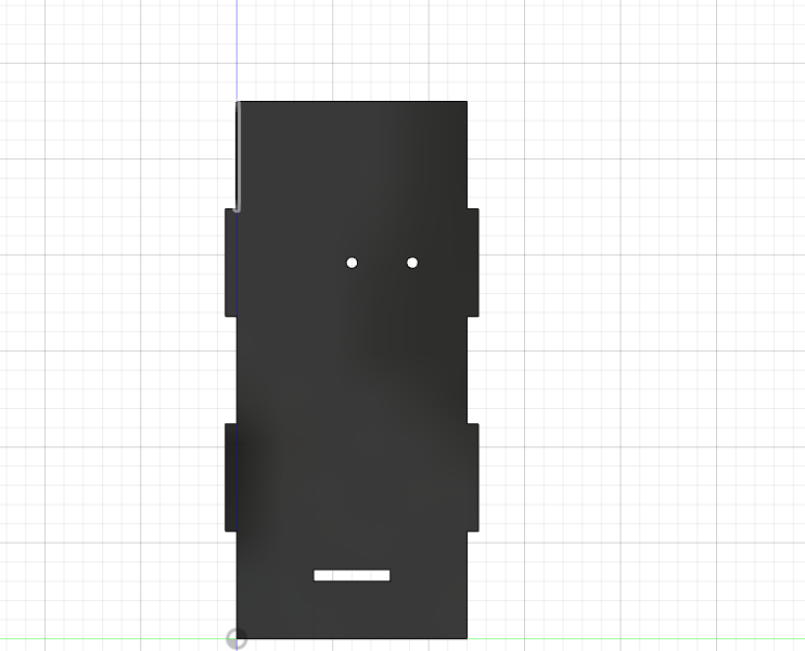
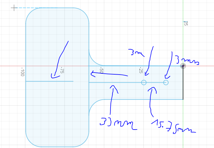
Once we have all that, we look for the first intersection so to speak left and we put a line in the center that measures 33mm to take out of that other one that measures 15.75mm, being able to eliminate the first 33mm, by staying as in the image then at each point of On the left, we add circles that are in "create" then to "circles" and we choose the first one by putting on each lower point that measures 3mm as seen in the image, eliminating the line then that joins them equally as seen in the image has to stay, we give "finish sketch" to go to "Extrude" placing 3mm
Finally we only give it an appearance as it was taught before and the second side would already be there!
The Structure 3- Third Side or Face


For the third side we follow the same process of creating a new sketch but choose the bottom side indicated in the image and with the "line" function we make the plane that is in the image starting from the center with 24mm then 3mm to the right and down 24mm and so on and then put on the right a 20mm with 3mm equally, then we have to create a line on the right as indicated in the image to indicate with the "mirror" tool those indicated in objects and mirror line as It is in the photo to put "okay" and that everything comes out later in what I believe we put in the center always remember a line as seen in the image so that it is already with mirror what is indicated in the image
We continue to put "finish sketch" and put 3mm extrude again and then personalize it with "Appearance" or just by pressing the letter "A" on the keyboard, remember that glass is recommended
The Structure 4-Final Side


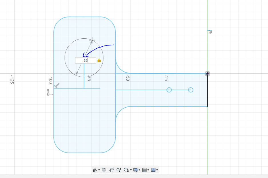

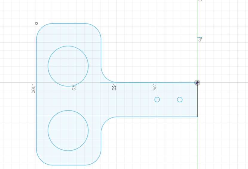

First, as always, we first create the sketch and then in this case select the side shown in the image, we begin to make the corresponding plane that is in the image with the measurements set, when we have the entire plane ready and joined, we go to the option "fillet" that can be seen in the image where it is located and we are joining each corner with its side that is seen in the image with 10mm each, done the above we create a line in the middle more or less long as seen in the image to then create another that one each side of reference and make a 33mm line together then another of 15.7mm and then at each point that you see put a 3mm circle like this in the image, after we have all that of the line that we took previously, which is located in the middle, in it we place another one to make a 25mm circle at the tip, then with the mirror function we place and select as it is in the image and place "Ok" so that it is done on the other side , ending c With all of the above we erase the lines that do not work for us as seen in the image
At the end give "finish sketch" and put the extrude function as in the previous parts with 3mm
Placing at the end with "appearance" the "glass" that is preferred
Assembly- FINAL STEP


As no plane is going to be created, it is not necessary to create a sketch
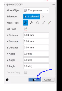
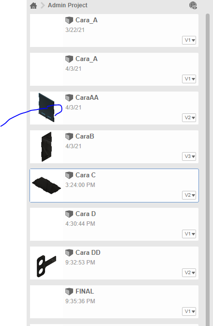
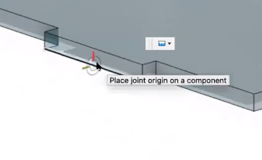
The assembly is the easiest of all, we only go to the left where we are going to see some small squares and we select what is seen in the image (there you can also see where the squares are) after that we select our sides that we are going to use but first we place the base and press left click on it and put in "Insert into current design" so that from there it is easier (the name varies by which you have put it but it is face or side C and it is the same process for the selection) we put "OK" and then we select the side we prefer in this case first select side A and we put it when it is there we go to the "Assemble" section that will be seen where it is in the image and we select "joint" when is selected we are located in the right box of our side A and we select the small line below and then the line below our right box of the base (as seen in the image)
And so on with the rest simply
Place another example with side B so that it can be better understood so that a product is left like this.
DOWLOADS AND MORE
This is not a step in itself but I leave the download links of the program and the parts so that you can download it and make it easier for you.
LINKS:
https://www.autodesk.com/campaigns/education/fusio...
PARTS:
https://mega.nz/folder/osZnFATA
The encryption key: ccfGy8KzQtE2QVmiqnHoSw
OR:
https://www.mediafire.com/folder/pjz4byr3h2l5m/PAR...
Thanks for watching this post and let's take care of ourselves in these difficult situations.