Gas Leak Detector Alarm System With Arduino Nano

by CarlosVoltT in Circuits > Arduino

68 Views, 1 Favorites, 0 Comments

Gas Leak Detector Alarm System With Arduino Nano

IMG_20210821_221620355-820x461 (1).jpg

In this tutorial we will see how to build a gas leak detector alarm system with Arduino Nano. 

In this tutorial we will see how to build a gas leak detector alarm system with Arduino Nano. We will see a list of the electronic components to be used, the assembly of the circuit, the source code, and finally we will test the operation of the system. This project is ideal for use in sources close to our home, where there is gas, such as a kitchen, stove or water heater.

Electronic components
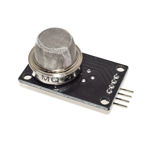
mq2 gas sensor

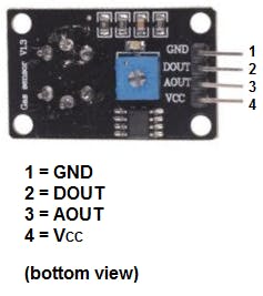
Pin-Out gas sensor Mq-2

Datasheet sensor MQ-2

Download–> MQ-2

Gas sensor (MQ2) is useful for gas leak detection (in home and industry). It can detect LPG, i-butane, methane, alcohol, hydrogen, smoke, etc. Based on its fast response time, measures can be taken as soon as possible. In addition, the sensitivity can be adjusted by a potentiometer (digital pin).

TECHNICAL SPECIFICATIONS

Operating Voltage: 5V DC

Fast response and high sensitivity

Detection range: 300 to 10000 ppm

Characteristic gas: 1000ppm, Isobutane

Sensing resistance: 1KΩ 50ppm Toluene 20KΩ in

Response time: ≤ 10s

Recovery time: ≤ 30s

Working temperature: -20 ℃ ~ +55 ℃

Humidity: ≤ 95% RH

Ambient oxygen content: 21%

Consumes less than 150mA at 5V.

APPLICATIONS

Gas Leak

Detector Industrial Gas Detector
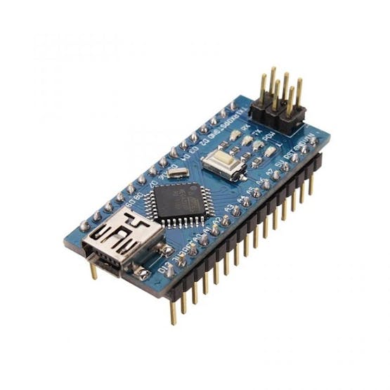


Arduino nano


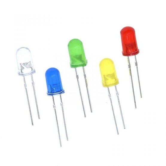
Six 5mm LED diodes of different colors


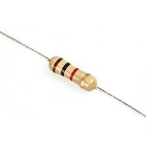
Six 1 Kohm resistors


A 5 volt buzzer


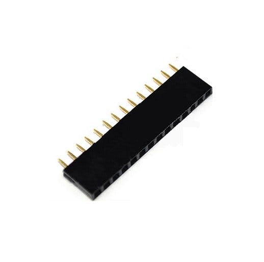
Female pins (4 pins total)


Male pins (2 in total)


Socket for the arduino nano
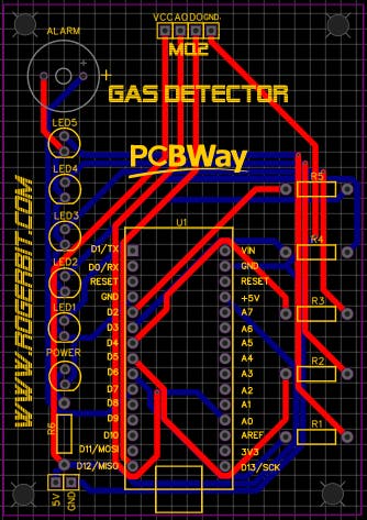


PCB

Download Gerber file –> Gerber_GAS_METER_MQ-2

Circuit


Source Code

int sensorMQ2=0;
void setup(){
Serial.begin(9600);//Configuración de la velocidad del puerto serial de arduino a 9600
//Se configuraran los pines 2,3,4,5,6 y 7 como salidas
//Del pin 2 al 6 van conectados a diodos led con su respectiva resistencia
pinMode(2, OUTPUT);
pinMode(3, OUTPUT);
pinMode(4, OUTPUT);
pinMode(5, OUTPUT);
pinMode(6, OUTPUT);
//Va conectado al Buzzer
pinMode(7, OUTPUT);
sensorMQ2=analogRead(A0);//Se lee el valor de la entrada analógica A0 donde está conectado el sensor MQ2
while(sensorMQ2>80){
Serial.print("Esperando a que se estabilice el sensor MQ2 (valor menor a 80): ");//Se imprime su valor por el terminal serial
sensorMQ2=analogRead(A0);//Se lee el valor de la entrada analógica A0
Serial.println(sensorMQ2);//Se imprime su valor por el terminal serial
digitalWrite(2, HIGH);
digitalWrite(3, HIGH);
digitalWrite(4, HIGH);
digitalWrite(5, HIGH);
digitalWrite(6, HIGH);
delay(500);
digitalWrite(2, LOW);
digitalWrite(3, LOW);
digitalWrite(4, LOW);
digitalWrite(5, LOW);
digitalWrite(6, LOW);
delay(500);
}
}
void loop(){
sensorMQ2=analogRead(A0);//Se lee el valor de la entrada analógica A0
Serial.print("Valor del sensor MQ2: ");
Serial.println(sensorMQ2);//Se imprime su valor por el terminal serial
//Se compara el valor de la variable sensorMQ2 si se cumple apagará todos los led
if(sensorMQ2<79){
digitalWrite(2, LOW);
digitalWrite(3, LOW);
digitalWrite(4, LOW);
digitalWrite(5, LOW);
digitalWrite(6, LOW);
digitalWrite(7, LOW);

}
//Se compara el valor de la variable sensorMQ2 si se cumple encenderá el led en el pin 2
if(sensorMQ2>80){
digitalWrite(2, HIGH);
digitalWrite(3, LOW);
digitalWrite(4, LOW);
digitalWrite(5, LOW);
digitalWrite(6, LOW);
digitalWrite(7, LOW);

}
//Se compara el valor de la variable sensorMQ2 si se cumple encenderá el led en el pin 2 y 3
if(sensorMQ2>120){
digitalWrite(2, HIGH);
digitalWrite(3, HIGH);
digitalWrite(4, LOW);
digitalWrite(5, LOW);
digitalWrite(6, LOW);
digitalWrite(7, LOW);

}
//Se compara el valor de la variable sensorMQ2 si se cumple encenderá el led en el pin 2, 3 y 4
if(sensorMQ2>160){
digitalWrite(2, HIGH);
digitalWrite(3, HIGH);
digitalWrite(4, HIGH);
digitalWrite(5, LOW);
digitalWrite(6, LOW);
digitalWrite(7, LOW);

}
//Se compara el valor de la variable sensorMQ2 si se cumple encenderá el led en el pin 2, 3, 4, y 5
if(sensorMQ2>200){
digitalWrite(2, HIGH);
digitalWrite(3, HIGH);
digitalWrite(4, HIGH);
digitalWrite(5, HIGH);
digitalWrite(6, LOW);
digitalWrite(7, LOW);

}
//Se compara el valor de la variable sensorMQ2 si se cumple encenderá el led en el pin 2, 3 ,4 ,5, 6 y el buzzer
if(sensorMQ2>240){
digitalWrite(2, HIGH);
digitalWrite(3, HIGH);
digitalWrite(4, HIGH);
digitalWrite(5, HIGH);
digitalWrite(6, HIGH);
digitalWrite(7, HIGH);//Se actica el buzzer

}
delay(100);//pequeño retardo antes de comenzar de vuelta
}