Gas Cap
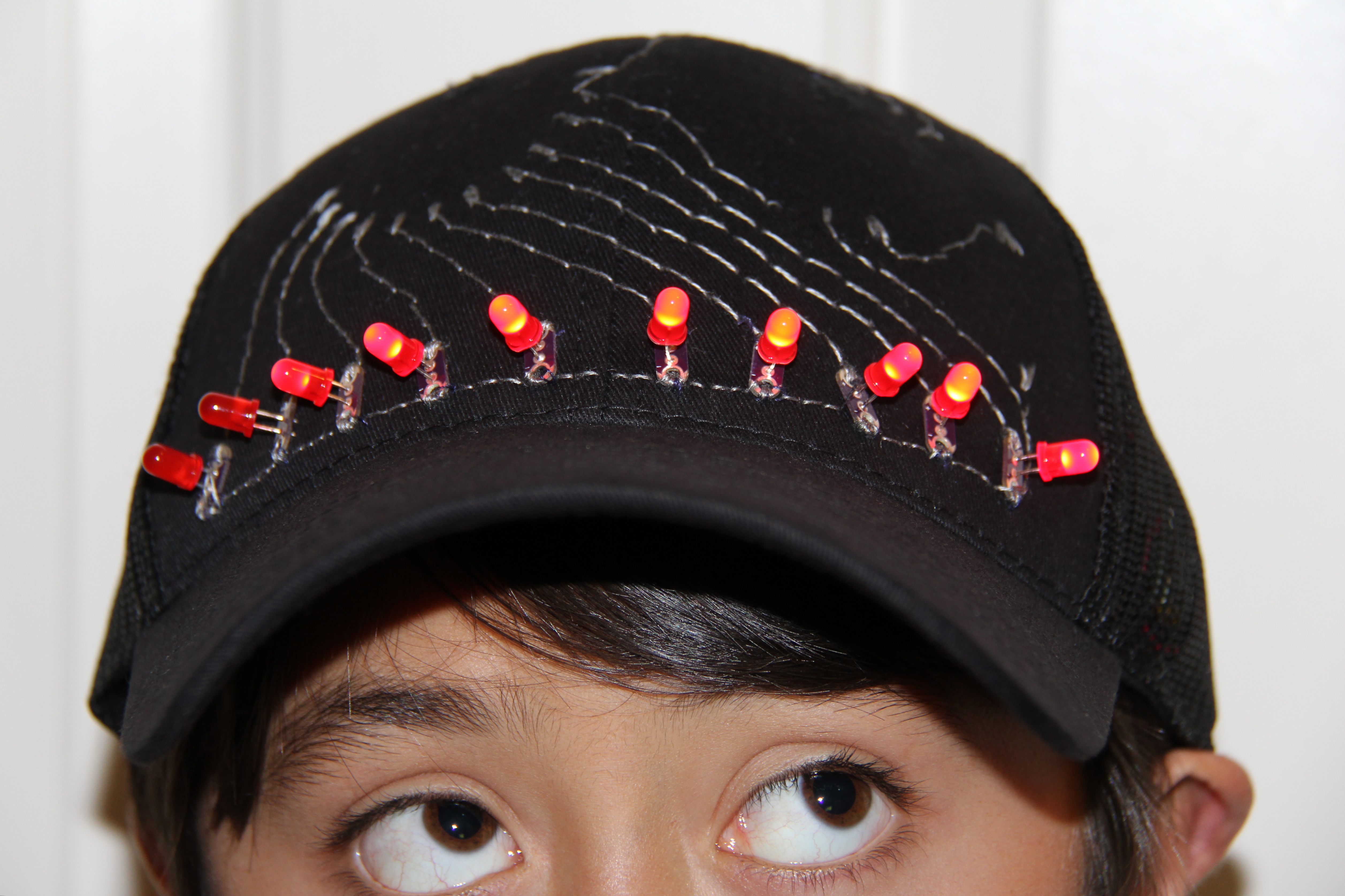
Since you've gotten into electronics, haven't you wondered if there is a fart sensor out there? I sure did. I discovered that if you use a methane sensor, especially the MQ-4, even at very low concentrations, it reads farts. What if you combined that into a hat with an LED Bar Graph and a XBee? Exactly. The Gas Cap was made with that in mind. For around $100, you can build your own Gas Cap, a human gas-operated LED Bar Graph on a hat. So, you fart into the methane sensor, wirelessly transmit that data to the hat, and watch the LEDs light up so that your friends can see how horrible it was.
Feel free to leave any questions or comments.
Feel free to leave any questions or comments.
Parts
You will need to purchase the following from Sparkfun:
Relevant Parts:
Methane CNG Sensor $5
330 Ohm Resistor $0.25 (2)
XBee Series 2 - Wire Antenna $26 (2)
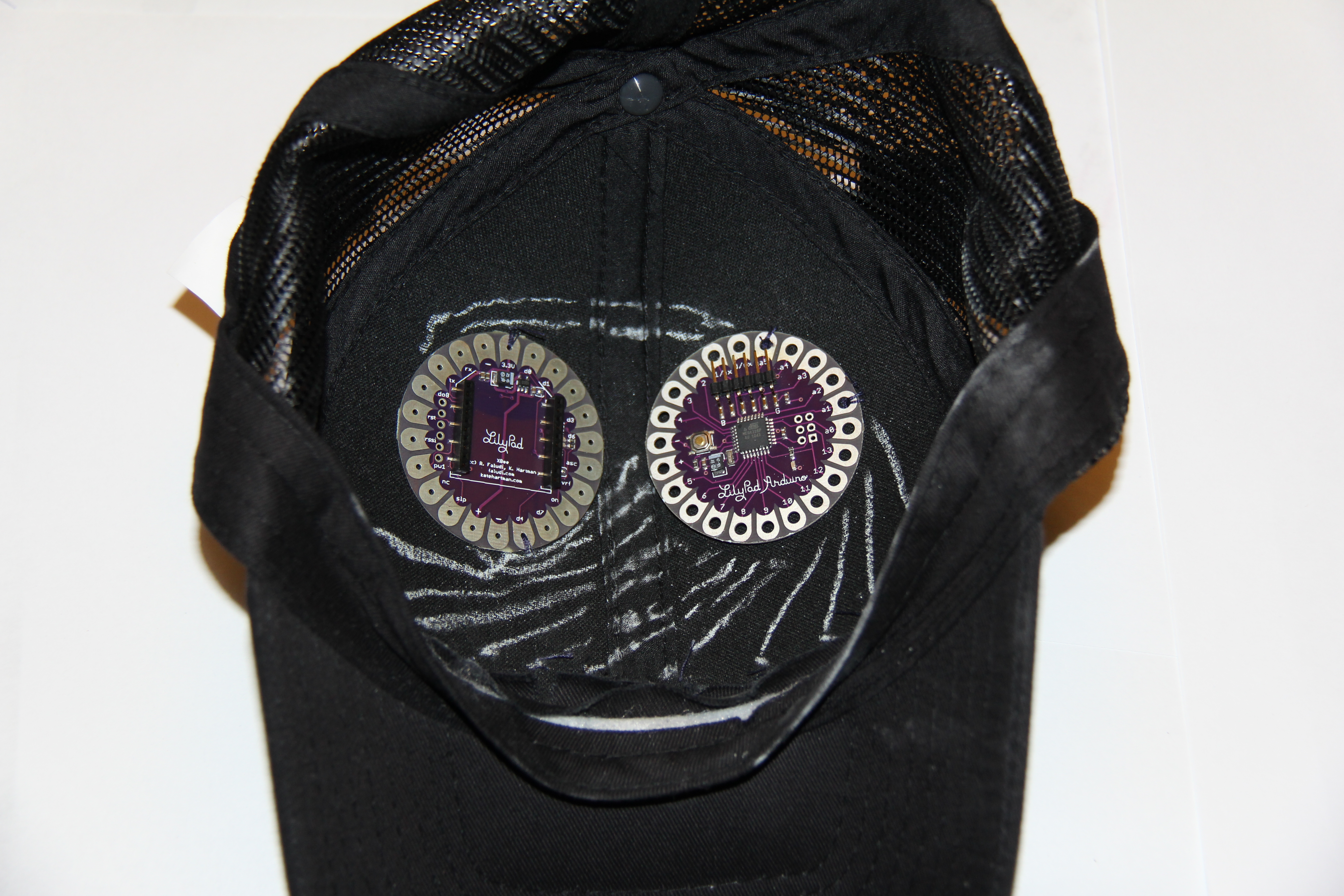
Lilypad Arduino 328 Main Board $22
Lilypad XBee $15
Lilypad LED PCB Set $5
Lilypad Simple Power $5
FTDI Basic 3.3V (for programming the Lilypad) $15
110mAh LiPo $7
850mAh LiPo $9
XBee Explorer $25
XBee Breakout Board $3
XBee Headers for Breakout Board $1 (2)
JST 2-pin Through-Hole Connector $1
SPDT Mini Power Switch $1.50
Other:
Red LED (10)
Green LED
LiPo Charger Basic $10
Mini-B USB Cable
A Black Soft Cotton Hat
Altoids Smalls mint tin
PC
Soldering Iron
Dremel
Needle
Conductive Thread $3
Long Wooden Stick or Umbrella
Hot Glue Gun
Chalk
Terminal Configuration
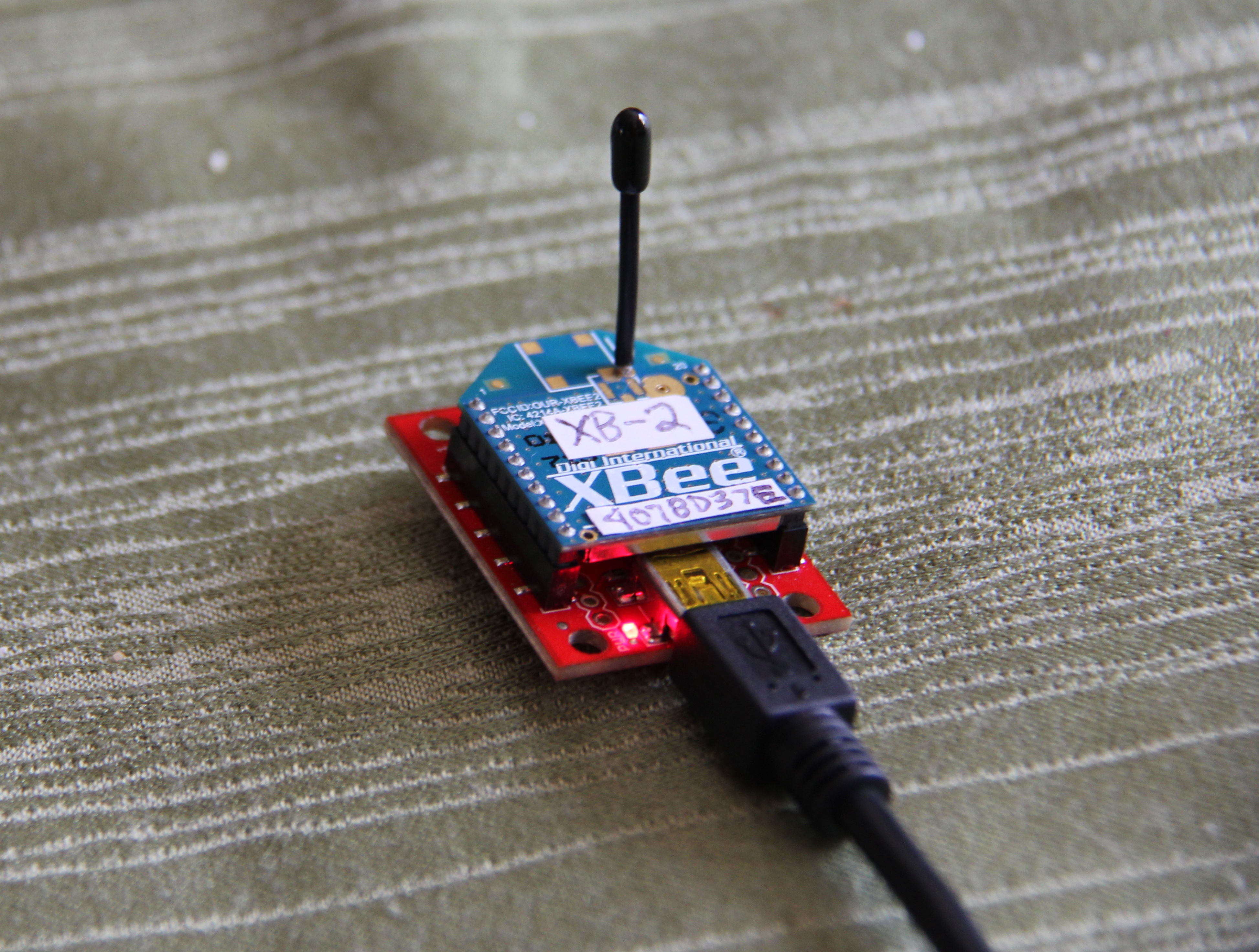
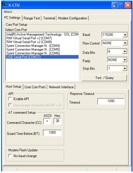
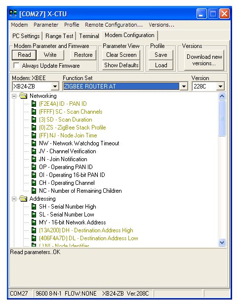
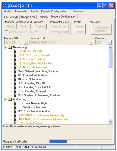
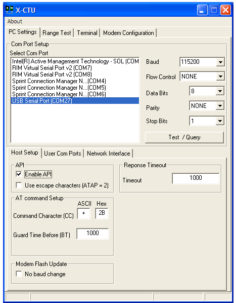
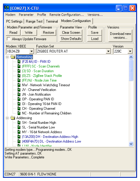
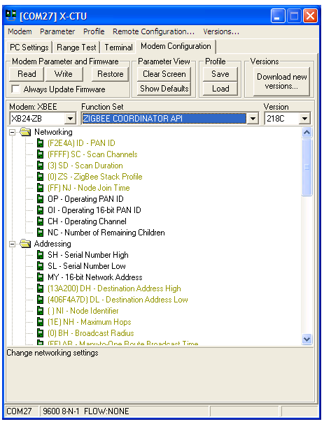
Now it's time to setup our XBees. We'll first load a new firmware on with X-CTU, and then set the parameters with your favorite terminal application. We need one XBee configured as a Router AT and another for a Coordinator API. This is because we are sending data from the router, but the only way to receive it is to set it in API mode.
Plug your XBee Explorer into your computer with one of the XBees on it already. Once in X-CTU, select the correct COM port (usually known as "USB Serial Port") and check the "Enable API" box. Go into the Modem Configuration tab. Click the leftmost drop down menu and select XB24-ZB. Click on the drop down menu to the right of it and select ZigBee Coordinator API. Click the Always Update Firmware box and then press write. After about a minute, it should be done uploading the firmware. Now, take out this XBee and put a "C" on it so that we remember it's the coordinator. Put the other XBee in and on the right hand drop down box, select ZigBee Router AT this time. Go back to the PC Settings tab, and then uncheck the "Enable API" box. Go back to the Modem Configuration tab, and then press the write button. After about a minute, it should be done uploading the firmware. Make sure to mark this one with an "R" so that we remember it's the router.
Wait! Stay in X-CTU! We need to program our coordinator in X-CTU because it is API mode. Every time you have an XBee in API mode, you have to configure it in X-CTU. Insert the XBee with a "C" on it. Check the enable API box in PC settings. Go back to the terminal and type in "+++" . Type in "ATRE" to restore the factory defaults. Type in "ATDH0013A200" to set the high part of the routers serial address. Type in "ATDL the low part of your router's serial address" to set the low part of your router's serial address. Type in "ATID 0" to set the PAN ID to 0. Type in "ATWR" to write your changes.
Go into your favorite serial terminal application and plug in your XBee Explorer with the XBee labeled with an "R", or your router. Type in the following commands after you type in "+++"!
- ATDH 0013A200
- ATDL the low part of your coordinator's serial address goes here
- ATID 0
- ATJN 1
- ATD02
- ATIR 64
- ATWR
Programming the Lilypad

You can download the Arduino code below. Put your FTDI Basic 3.3V on the Lilypad and plug into the computer. Select Lilypad Arduino w/ ATmega328 from the Arduino boards menu. Upload the code to the Lilypad. Charge your LiPo's now so that they will be fully charged for step 6.
Downloads
Assembling the Hat
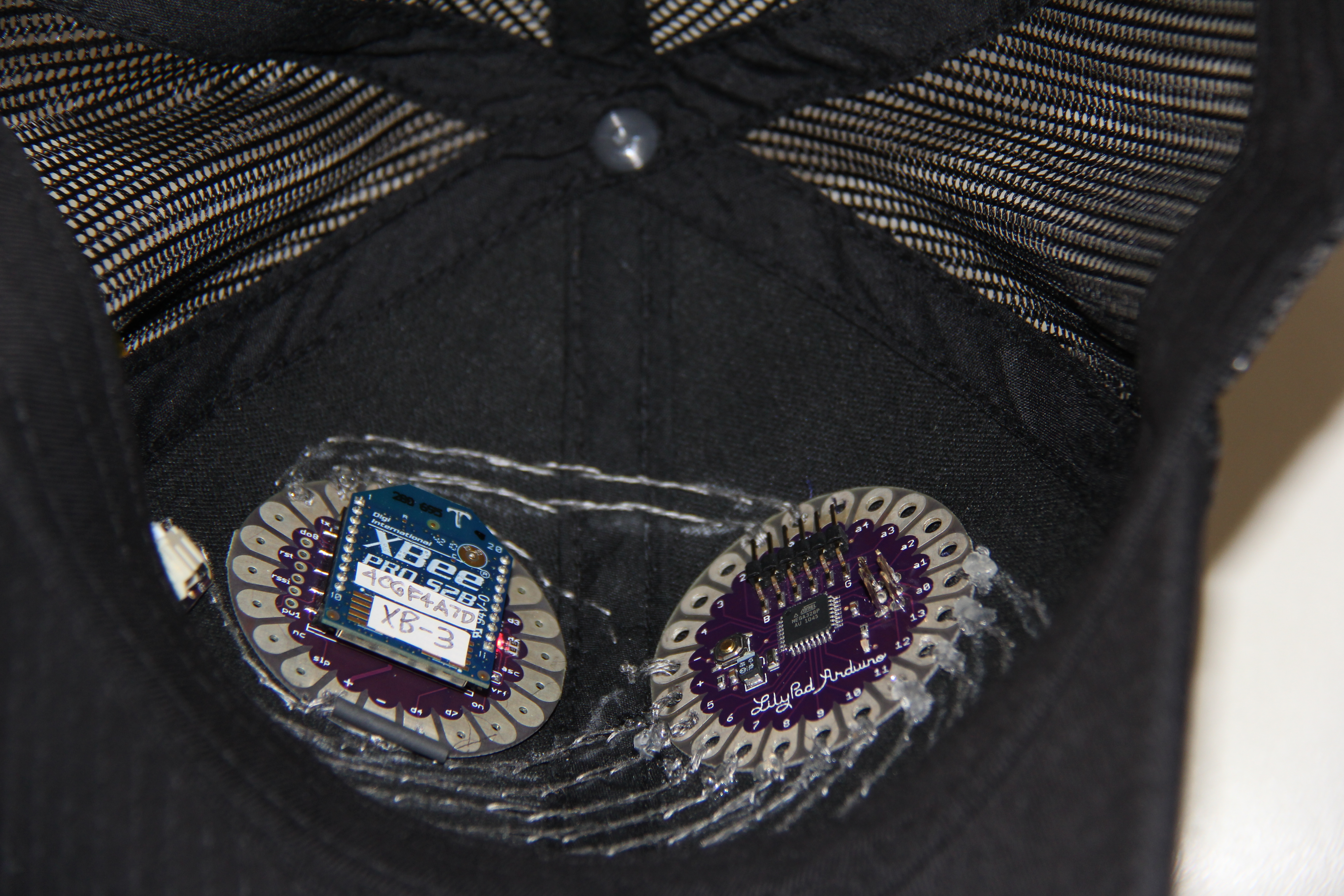
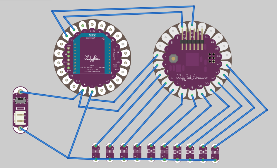
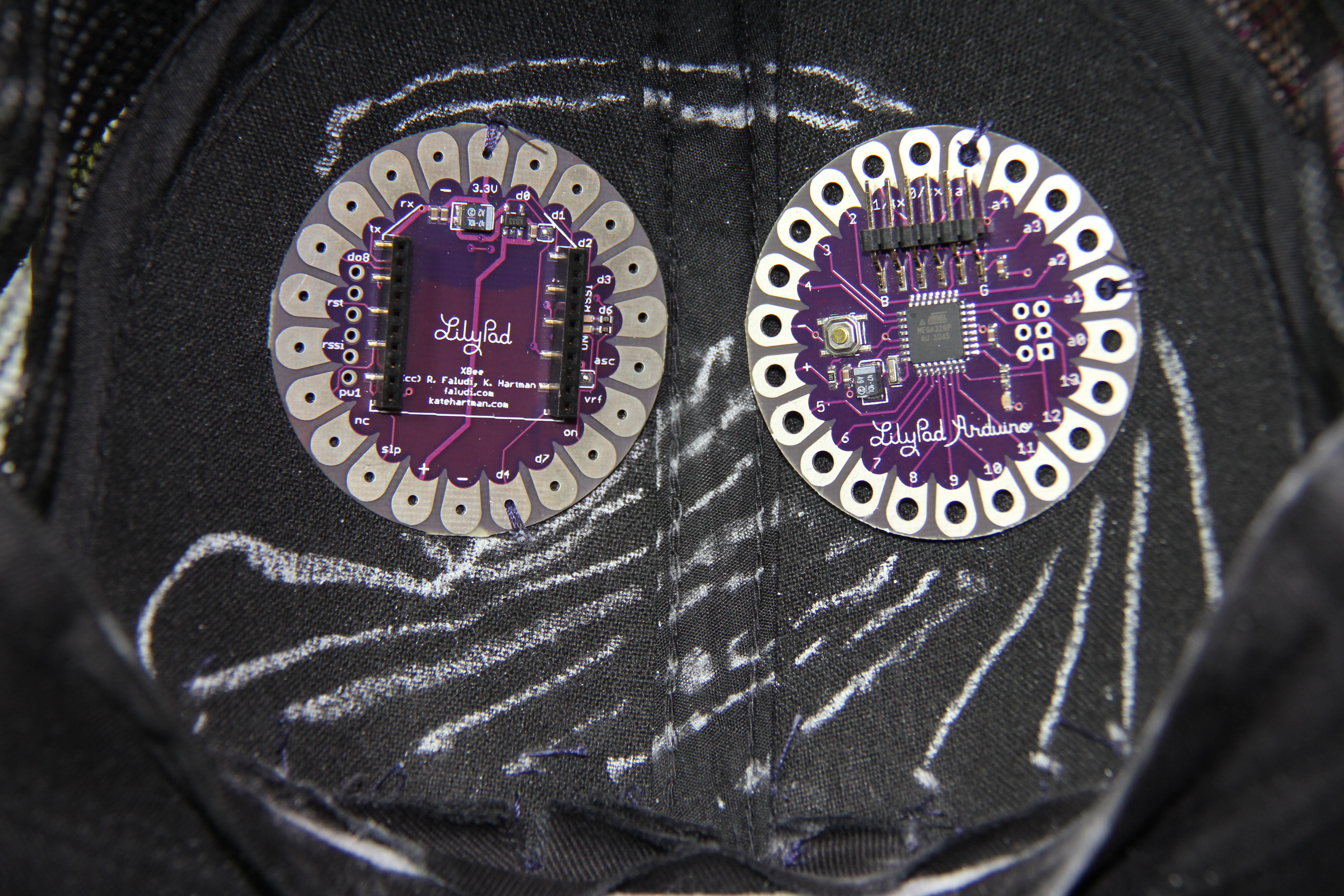

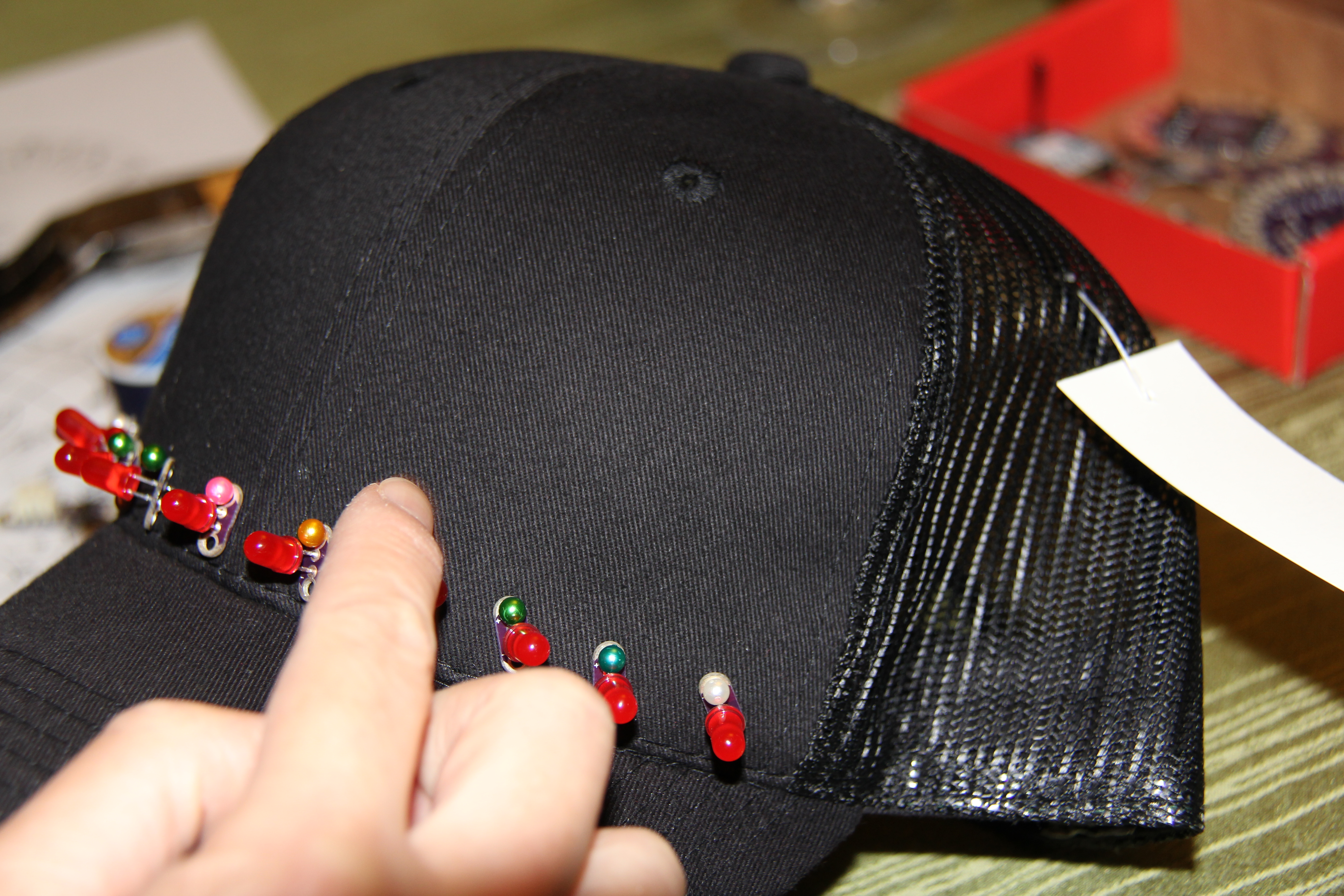
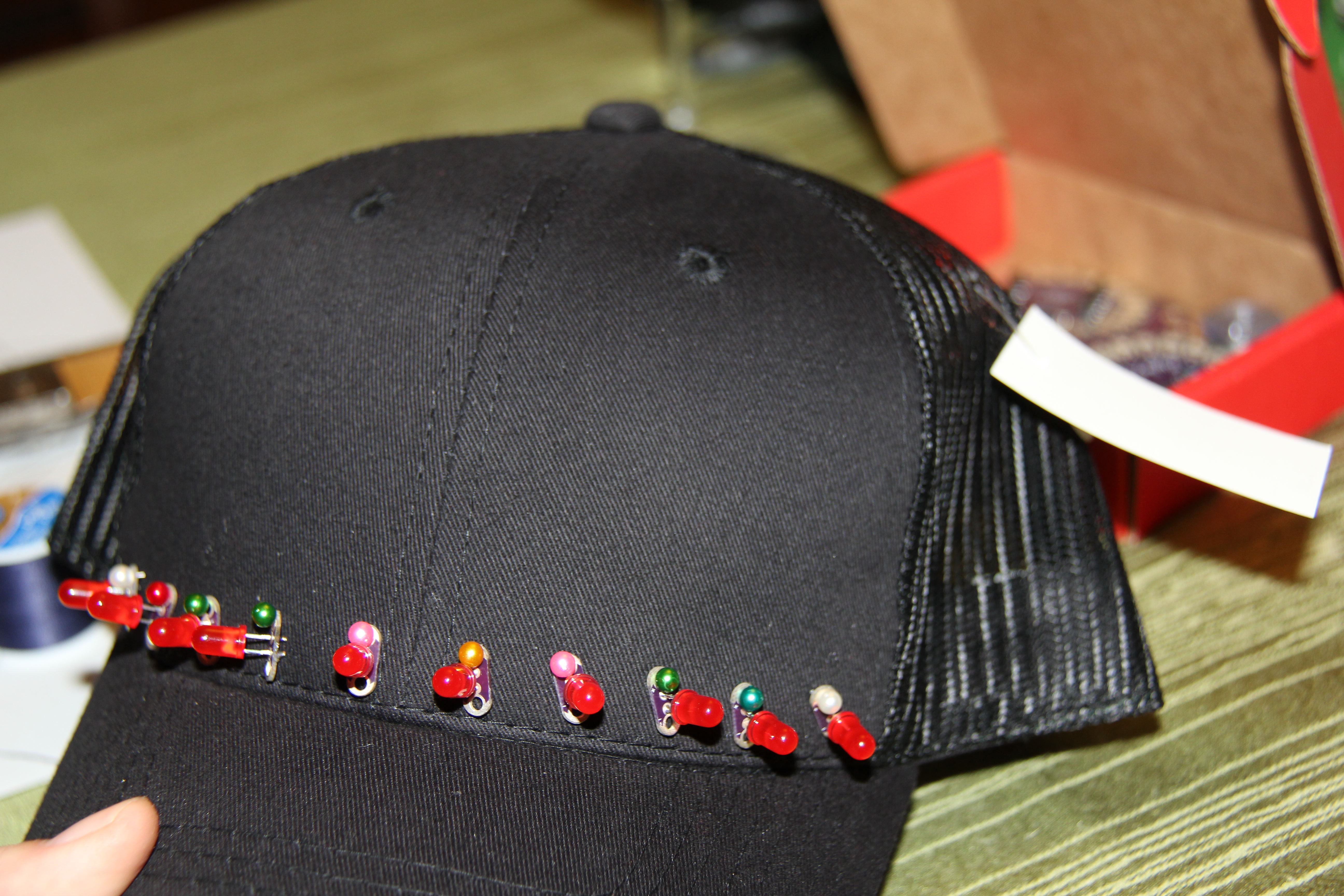
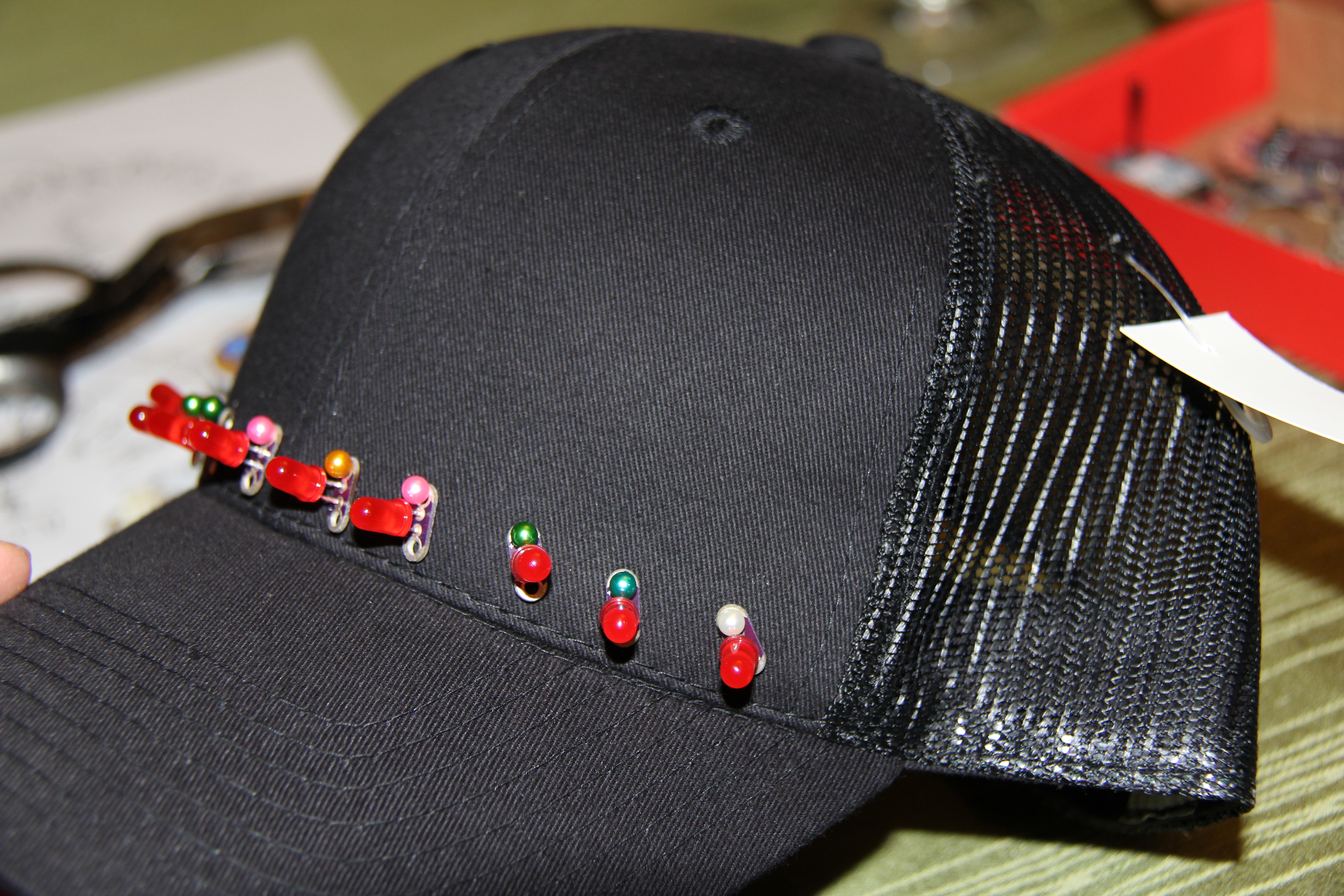
Now, take your cap and make sure there are no metallic parts in it. Use a soft cloth hat (not a hard polyester one with cardboard inside like I used which was very difficult to stitch). Decide where you want your 10 LEDs, and also where the Lilypad and Lilypad Xbee, and Lilypad Simple Power are going to be located. Using regular thread (not conductive), sew these in place with a few stitches each just to stabilize them a bit. It is a lot easier than using pins, and then you won’t poke yourself.
Take a piece of chalk, and map out all your connections, just to make sure. The chalk will brush off later.
Using the conductive thread, sew all your connections as planned. Make sure that the power source is as close to the Lilypad main board as possible. Remember to make good knots at the end of the stitch and then cut closely so as not to overlap the threads and short circuit. I also put hot glue at most of the knots to make sure they didn’t unravel. You will need to use a small insulation tube where the + to + overlaps another row of stitches. Put at least 3-4 passes through each of the Lilypad holes to ensure good conduction.
Assembling the 2nd Part of the Gas Cap
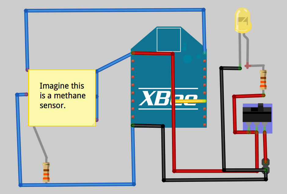
Use the Fritzing example to understand the connections.
Wire up the methane sensor like so, but use your 330 ohm resistor instead of the 10K that they show in the example. The reason for this is that the XBee's voltage reference is 1.2V, so we need a really low value, and replacing the voltage divider resistor it the exact thing to do.
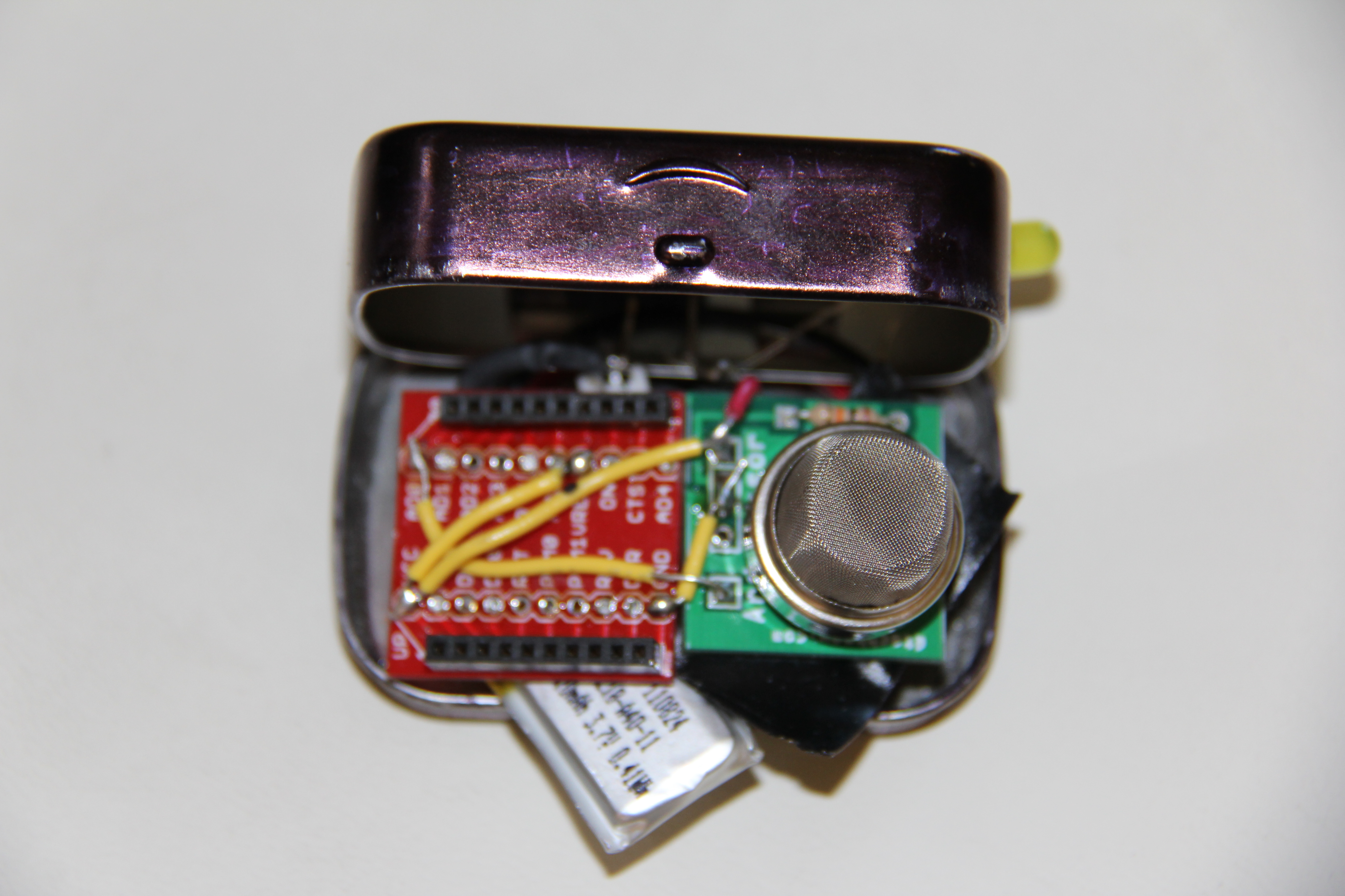
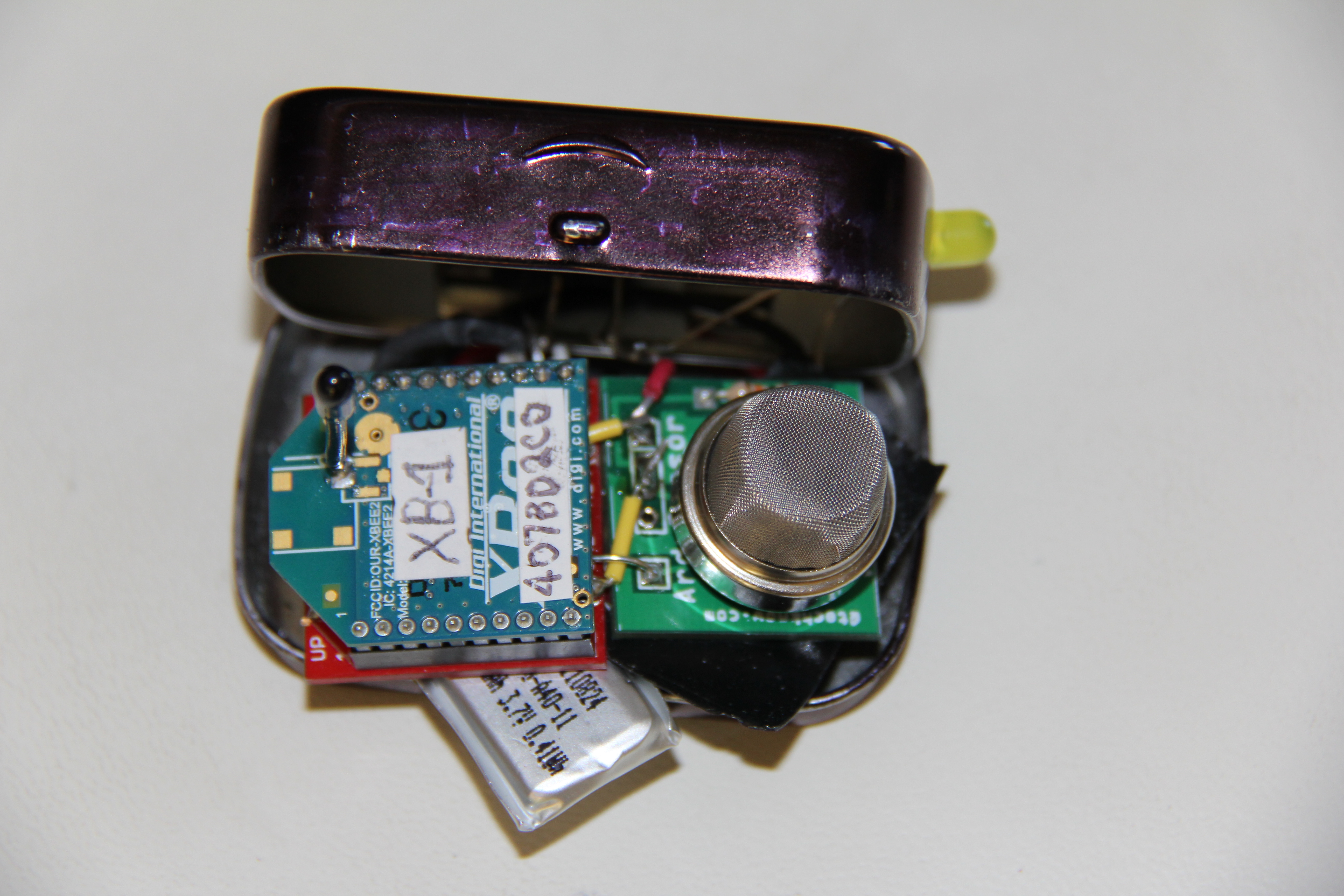
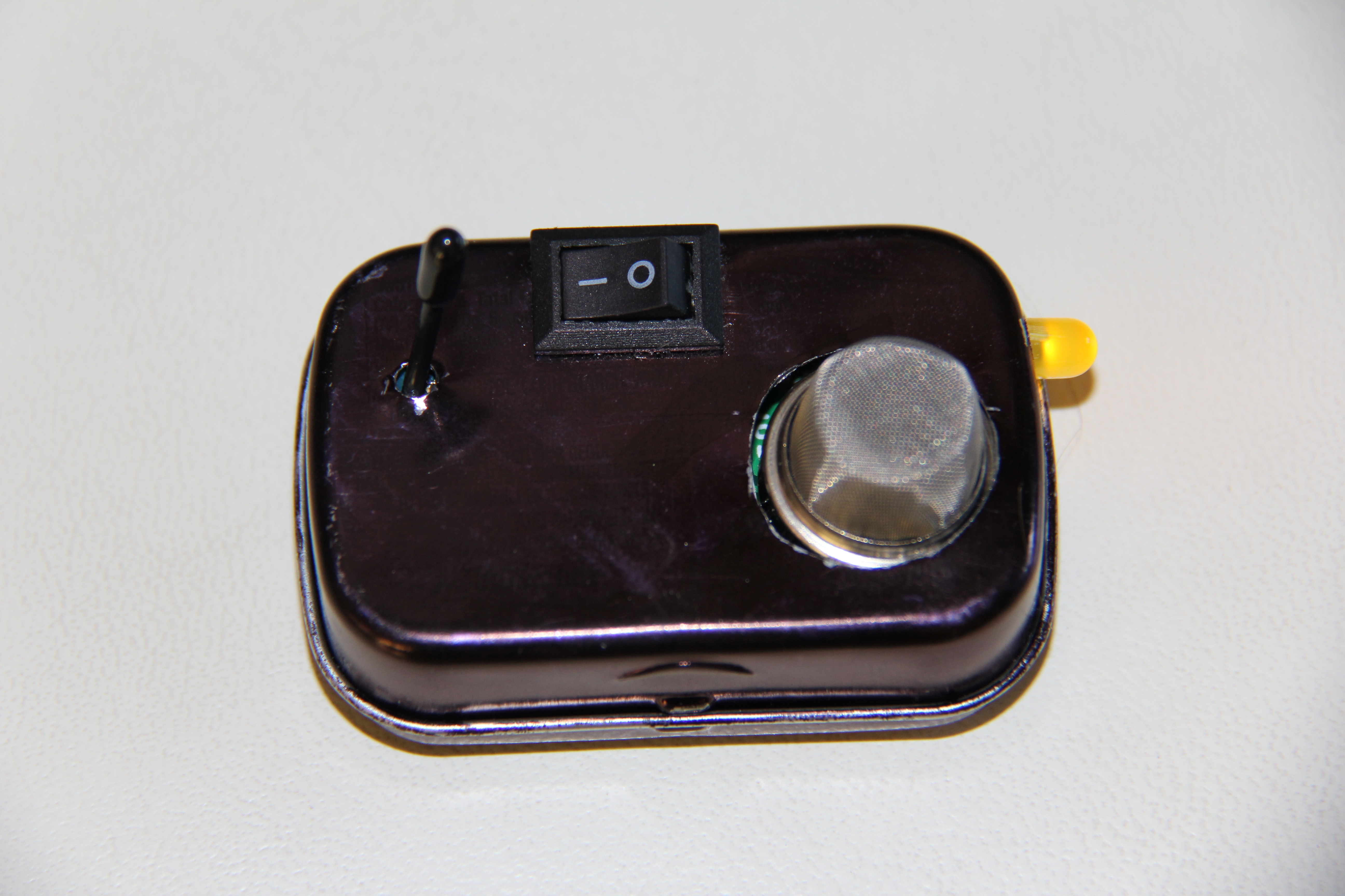
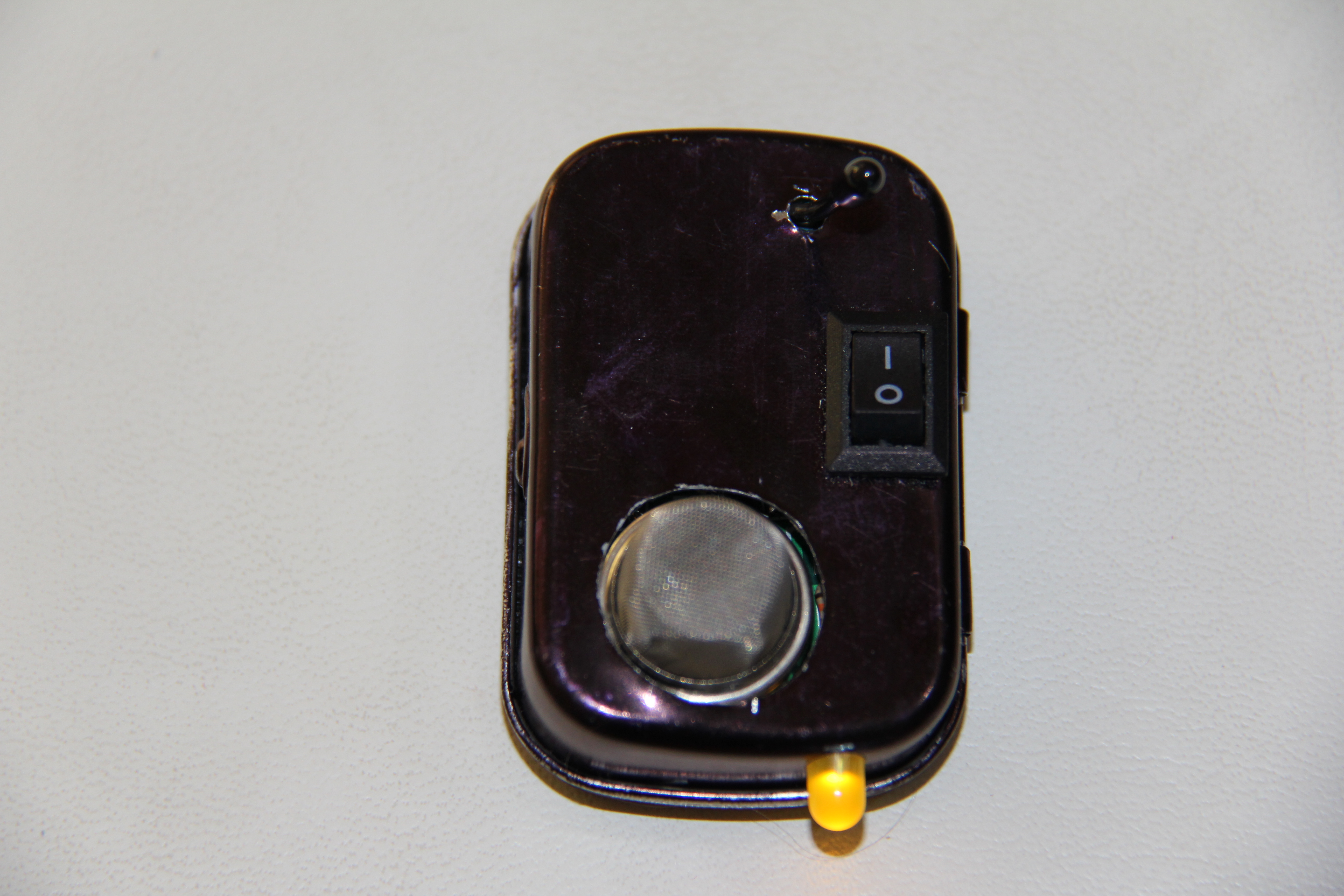
Solder the XBee headers to the breakout board (not the actual XBee!) and attach one of the XBees to the new breakout board. Looking at the Altoids tin, flip it over so that the clamshell end is at the bottom. Open the top up and of the left, rotate the XBee breakout board so that the top of the breakout board is facing left. Place the methane sensor in the right of the bottom of the tin. Dremel the Altoids tin on the bottom so that it makes a small hole for the XBee's antenna. Dremel a bigger hole for the methane sensor to the right of that. Make sure it fits, and then take out the sensor and the breakout board. Take the XBee out of the breakout board. Put electrical tape on all sides of the tin so that no metal is showing because we don't want it to get shorted out!
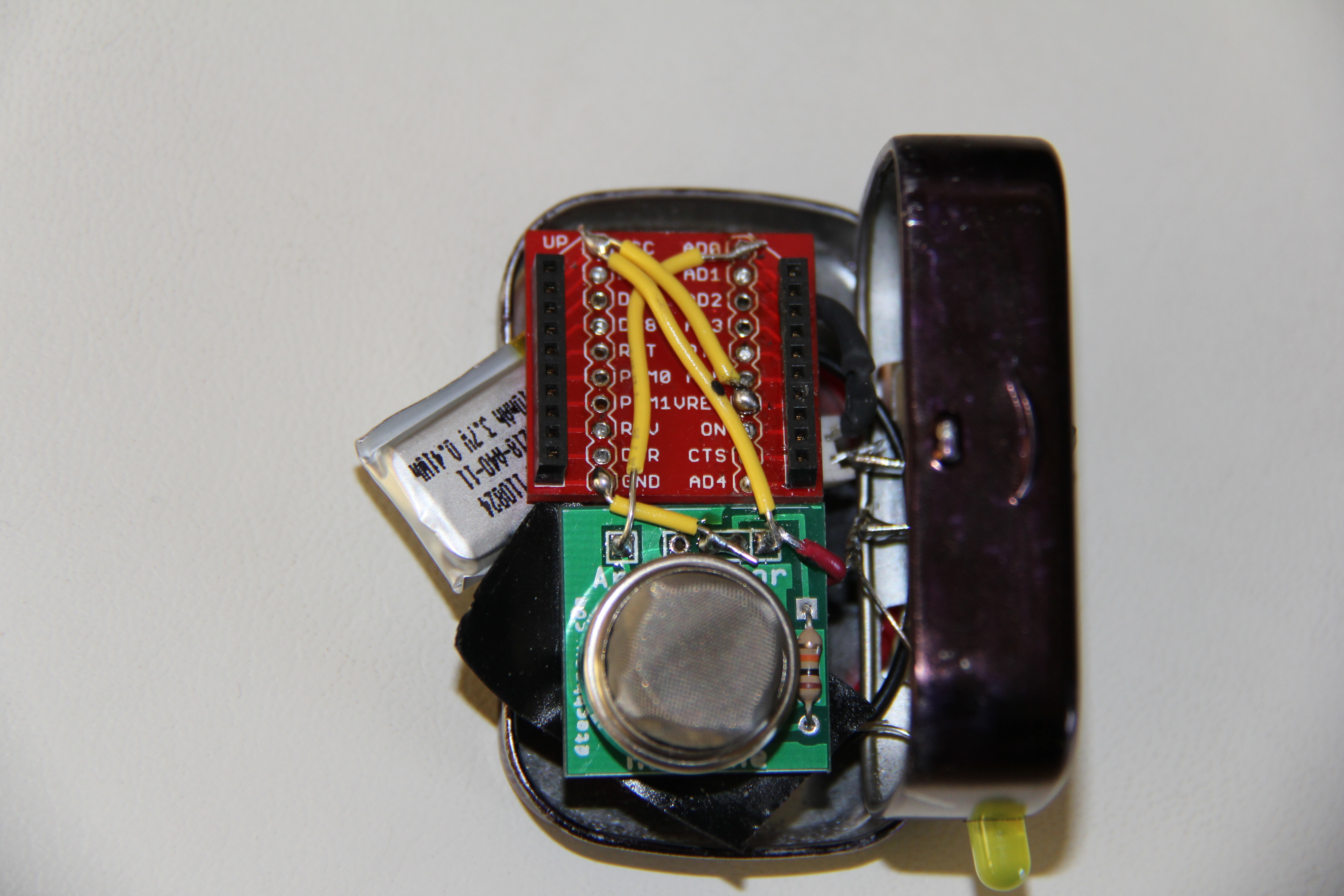
Now it's time for soldering! Connect the analog input pin on the methane sensor to pin 20 of the XBee breakout Board (the top right pin). Connect +5V of the methane sensor and connect it to VCC on the breakout board. Connect GND's together on the sensor and then connect to GND on the breakout board. Connect VREF on the breakout board to VCC on the breakout board. Attach an LED and resistor between ON on the breakout board and GND. Wire up a switch to the LiPo jack in-between VCC and GND. Check the polarity of the LiPo jack by inserting the LiPo the correct way and soldering. Cut the methane sensor's leads so that they do not touch the Altoids tin.
With the Altoids tin open, rotate it 180 degrees so that "smalls" label on the tin is facing you. Put your XBee in the socket that we attached to the methane sensor, the switch, and the power LED. Put the whole jumble of wires including the XBee socket, methane sensor, the switch, and the power LED into the altoids tin facing down so that the Xbee antenna and methane sensor go out of the holes that you Dremeled. Put the 110mAh LiPo on top of the whole mess and connect it to the LiPo jack connected to the XBee socket. Close the Altoids tin and flip over.
Stay Away!
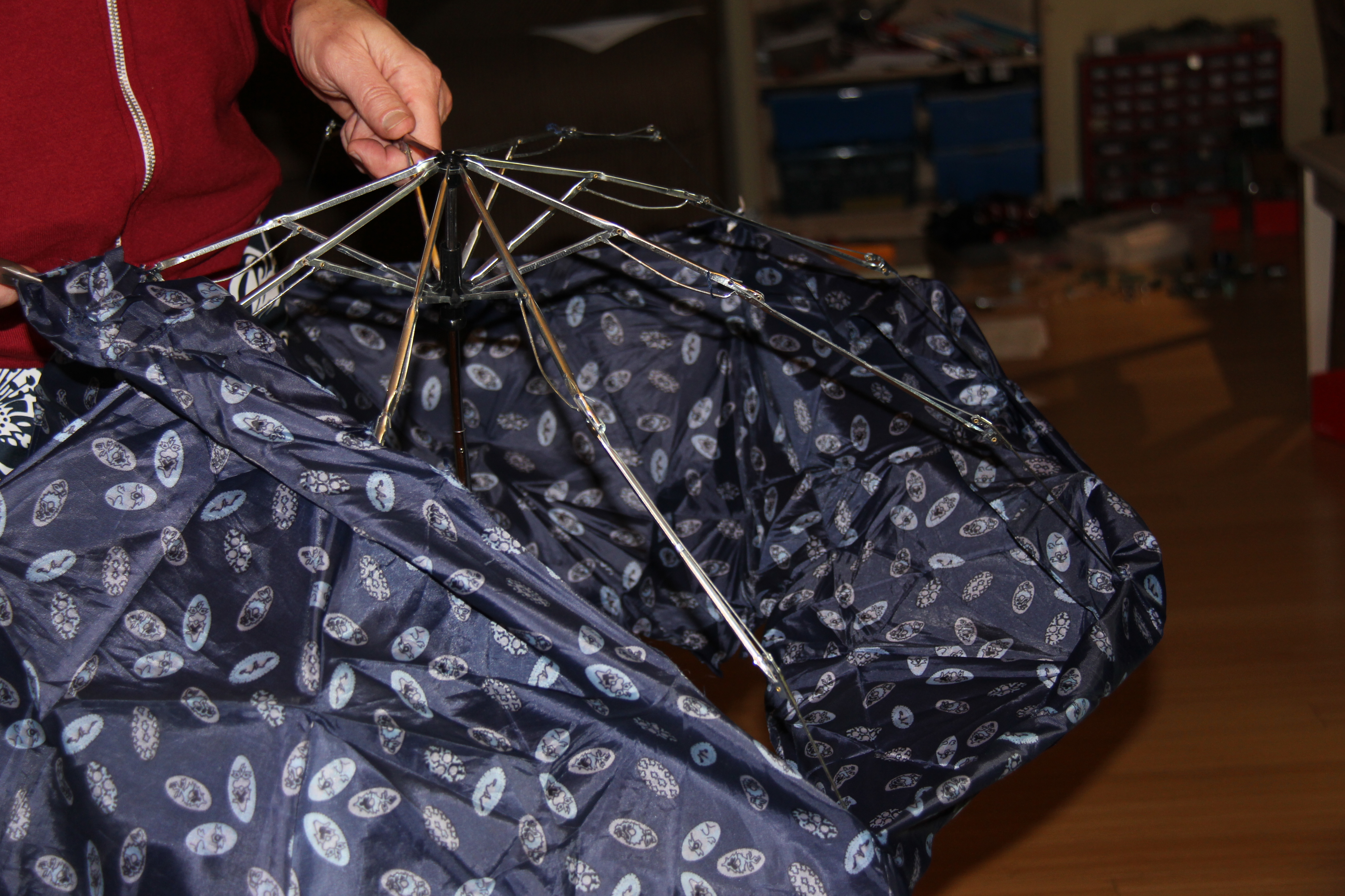
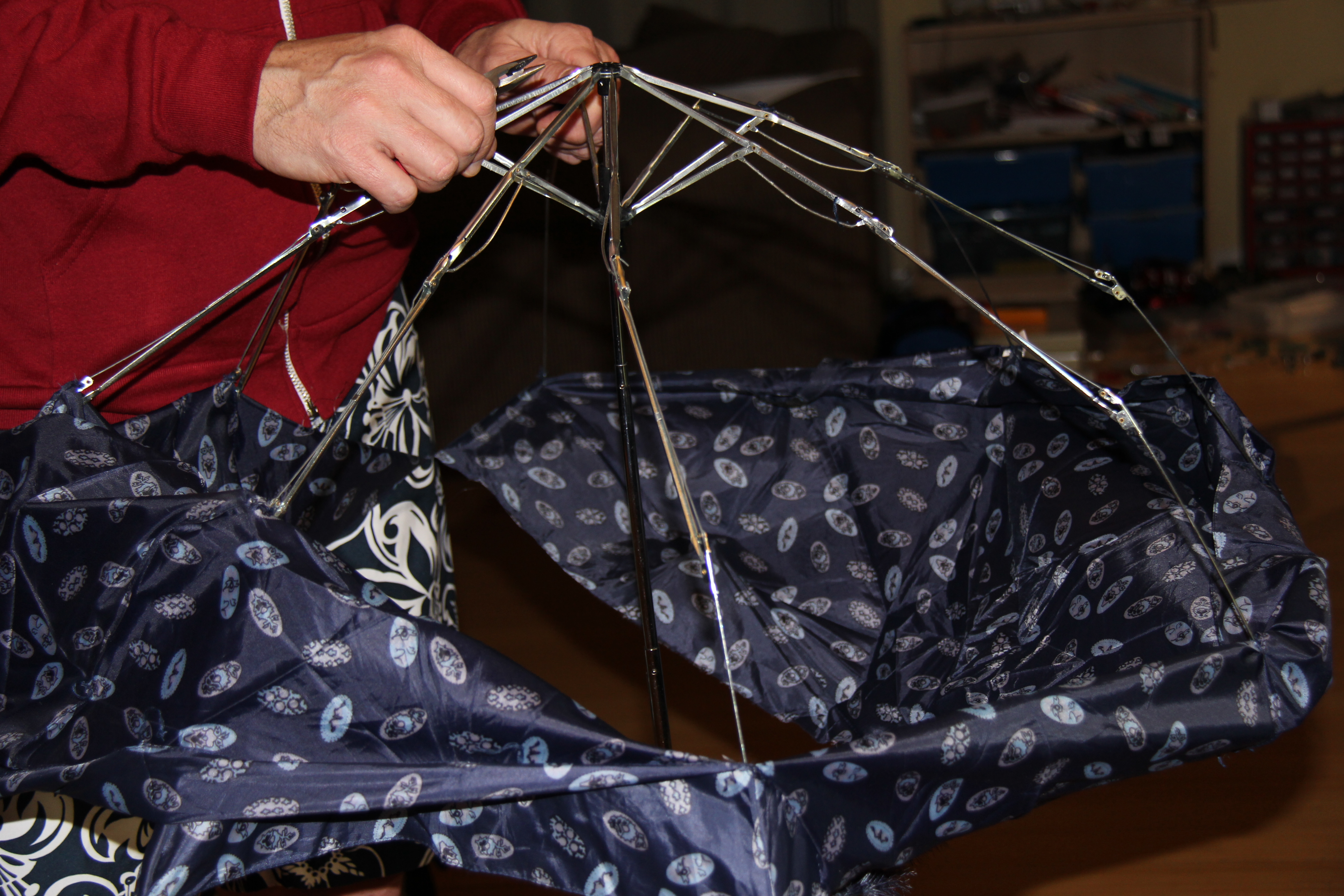
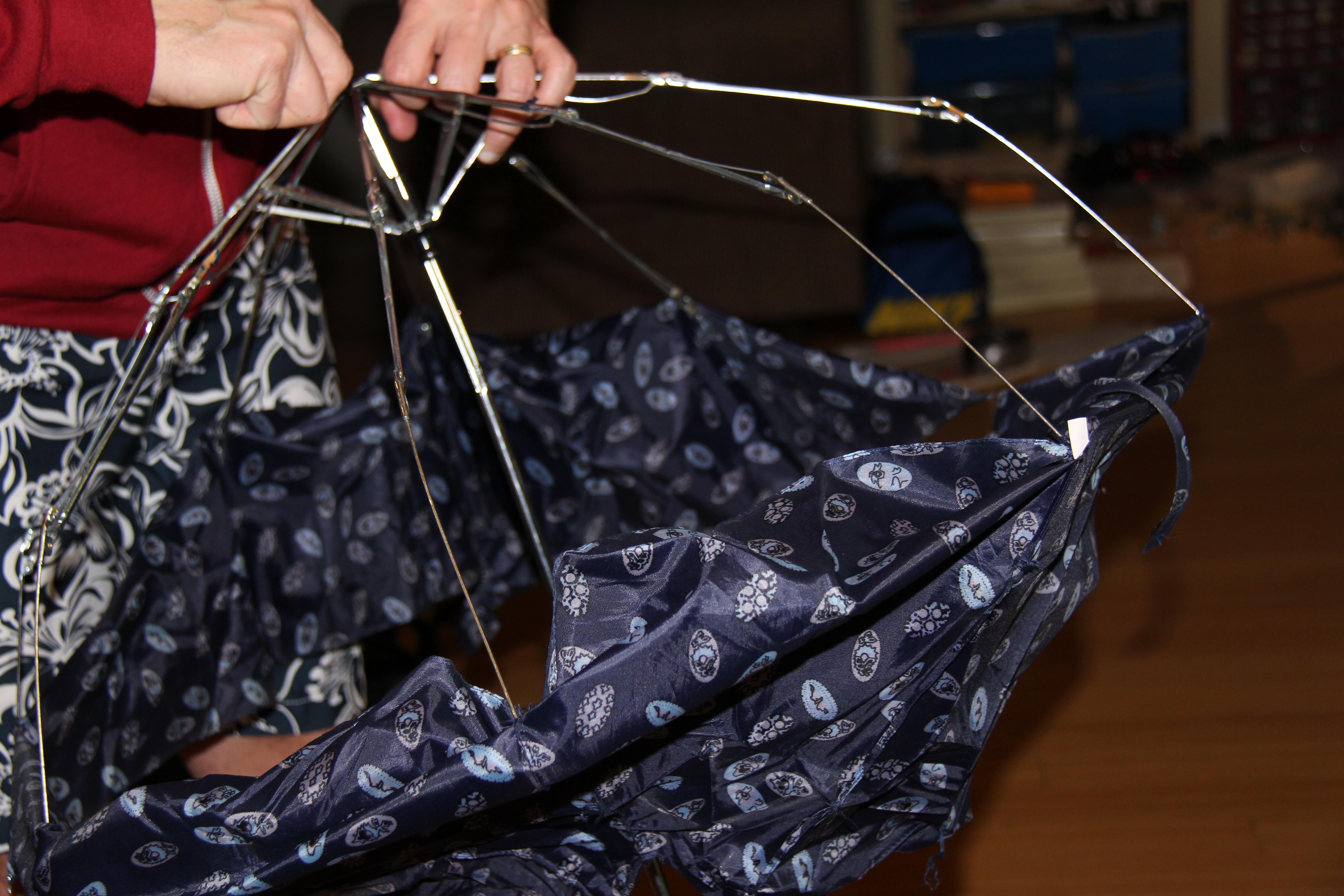
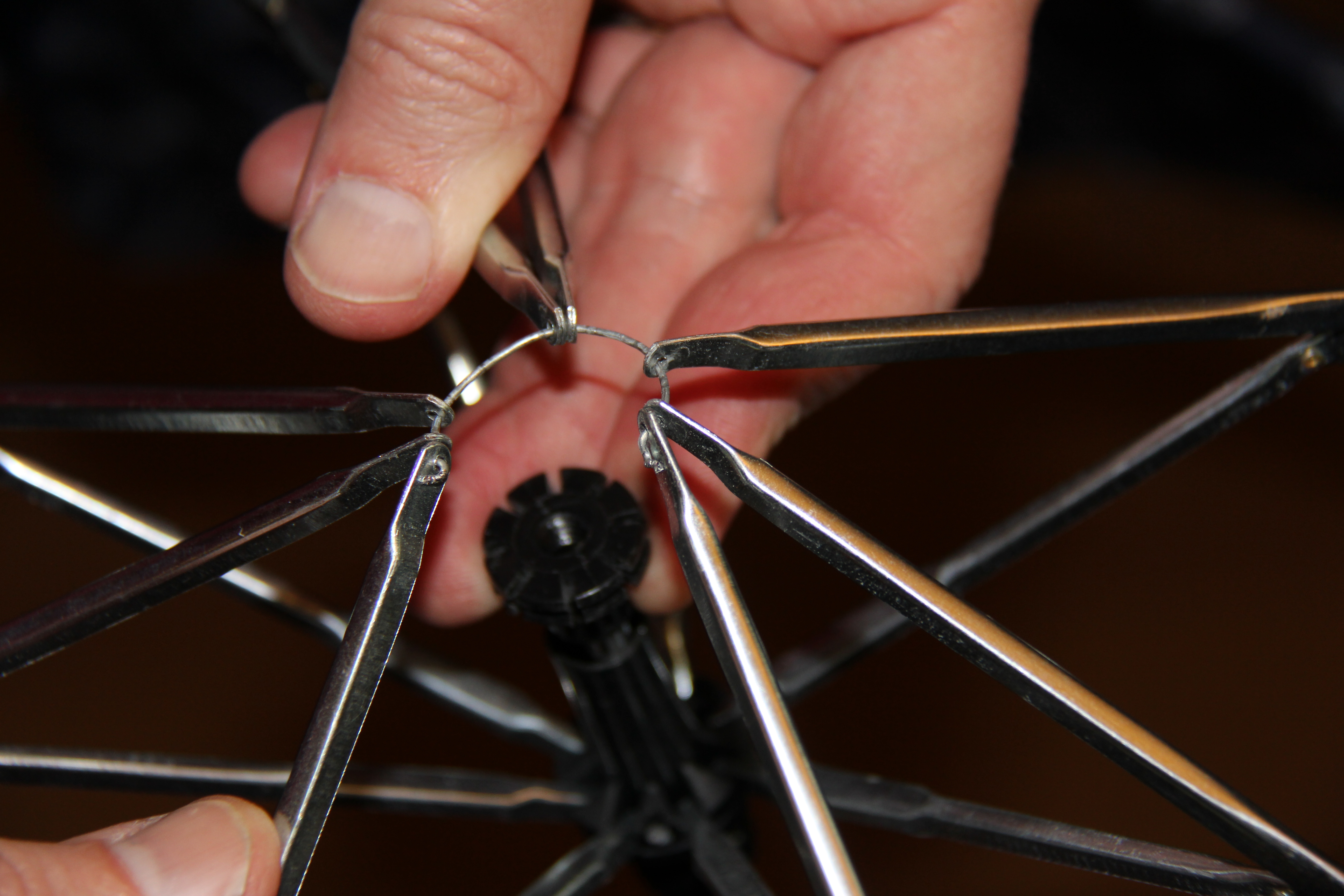
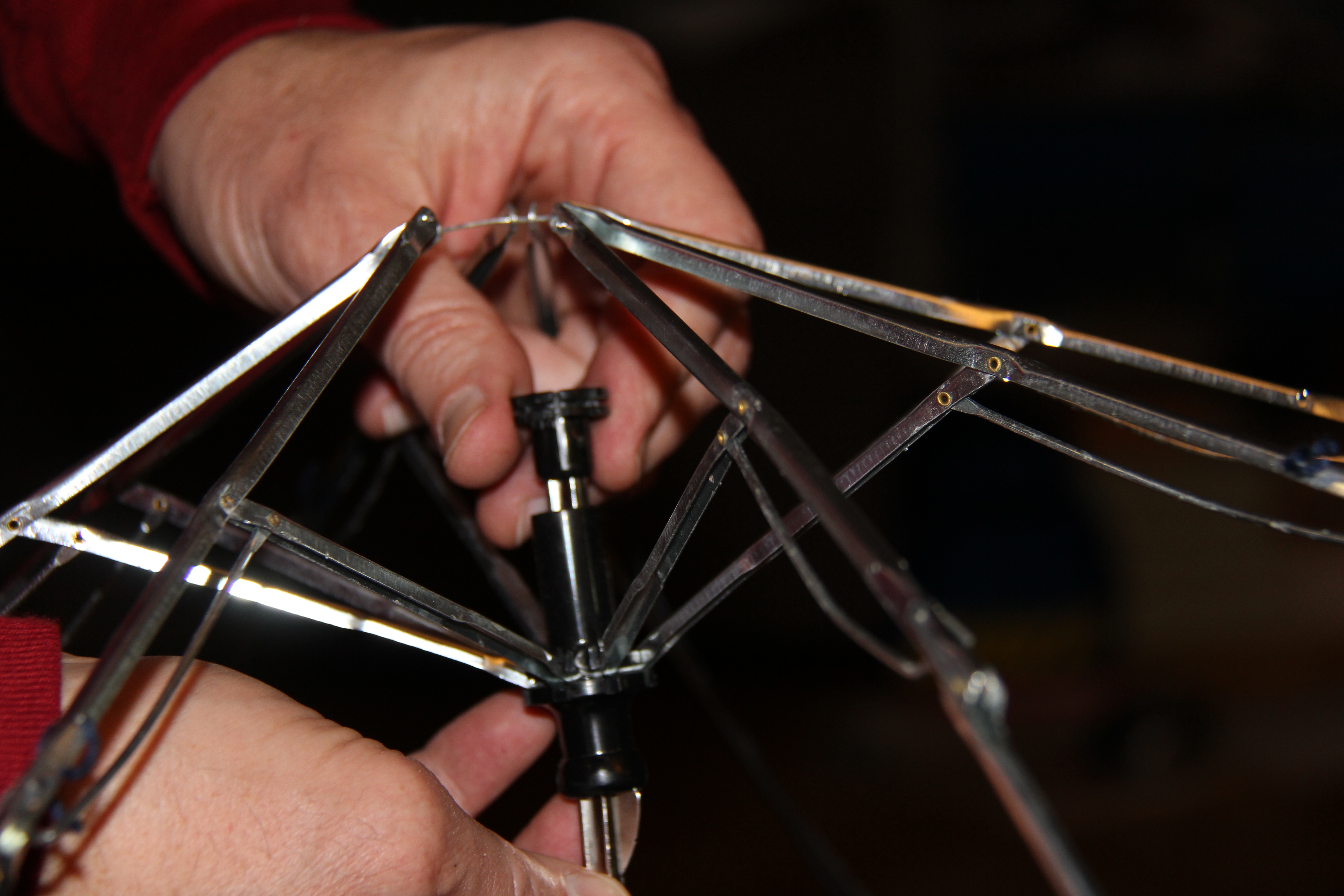
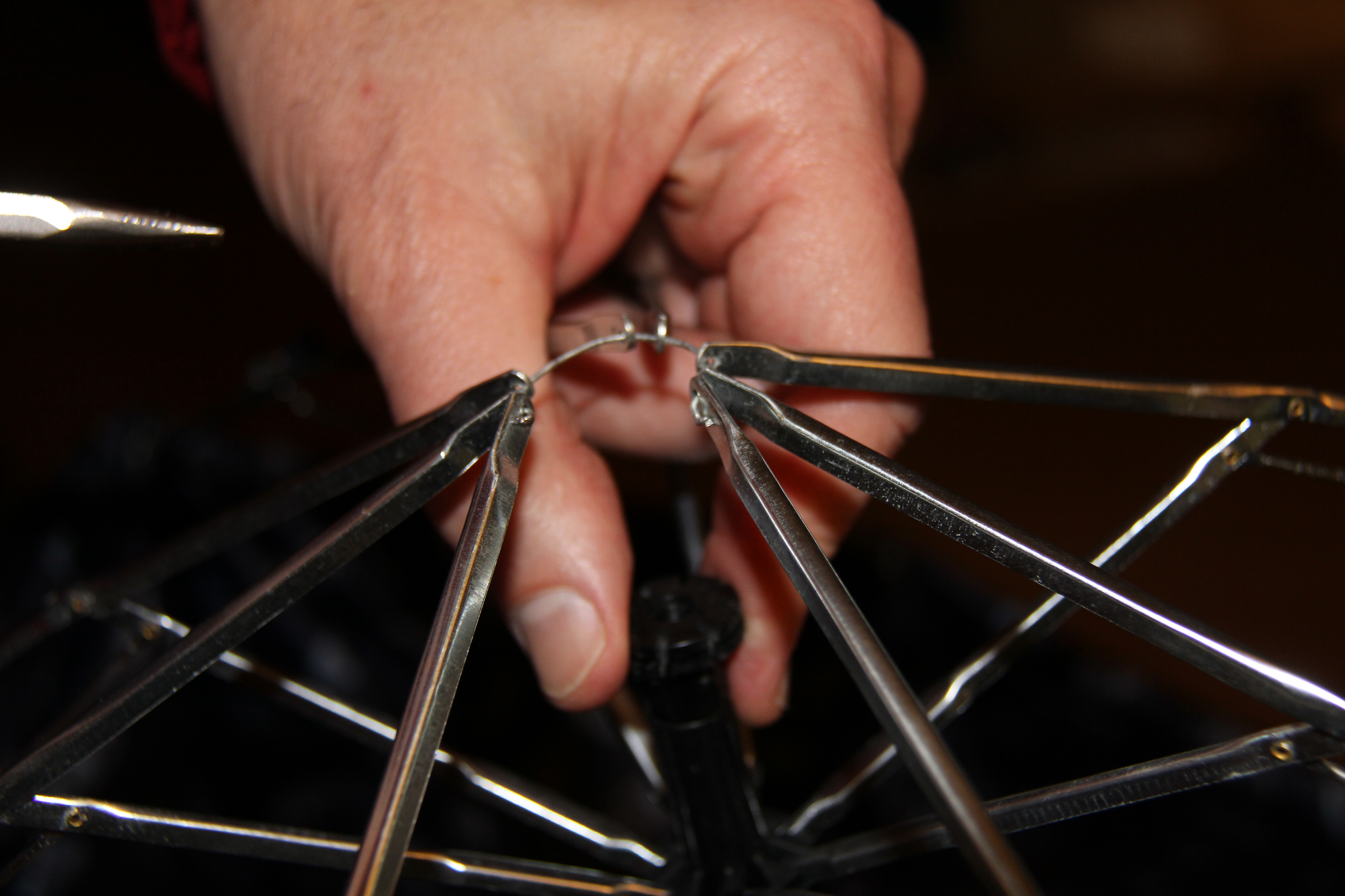
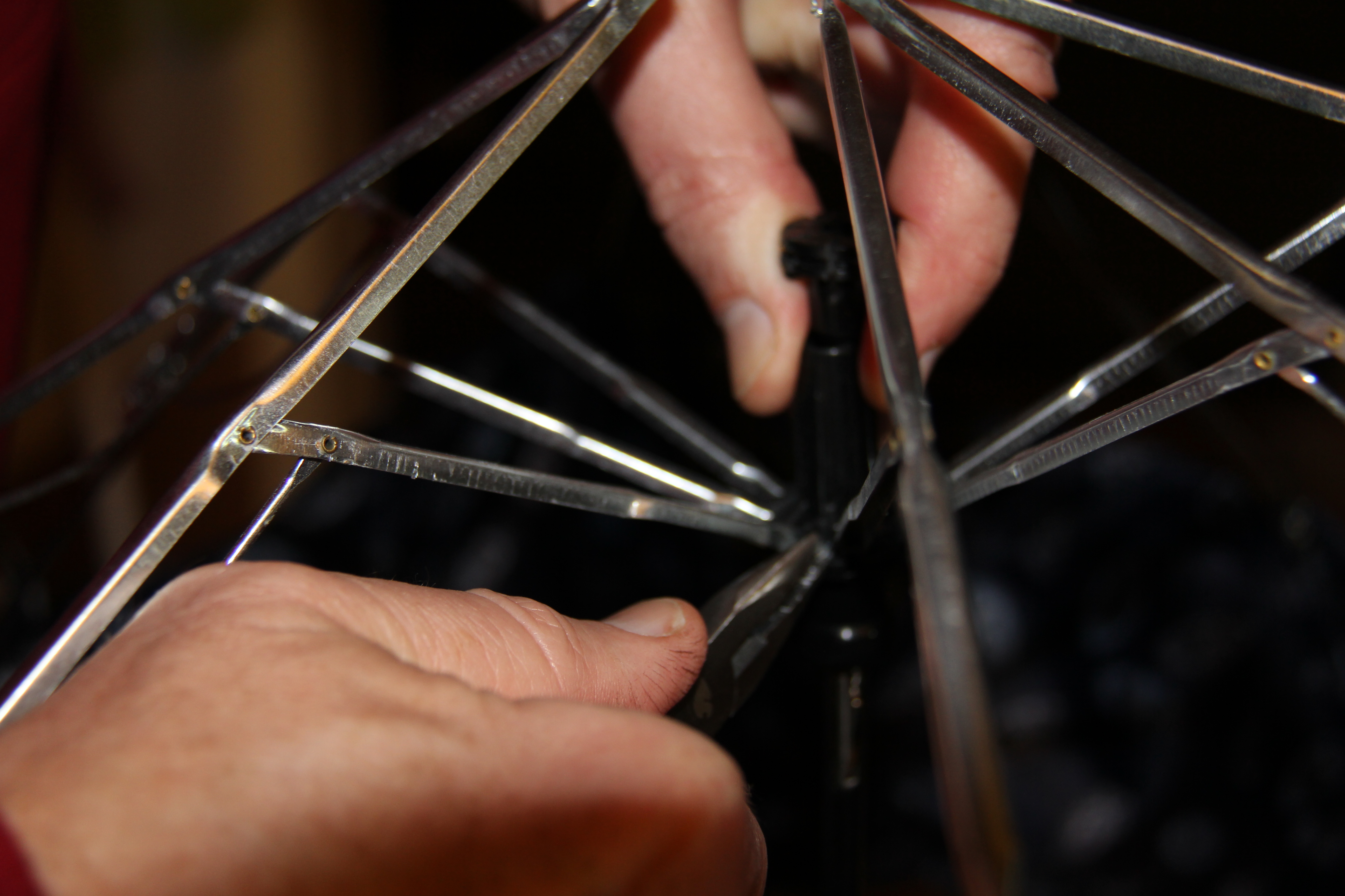
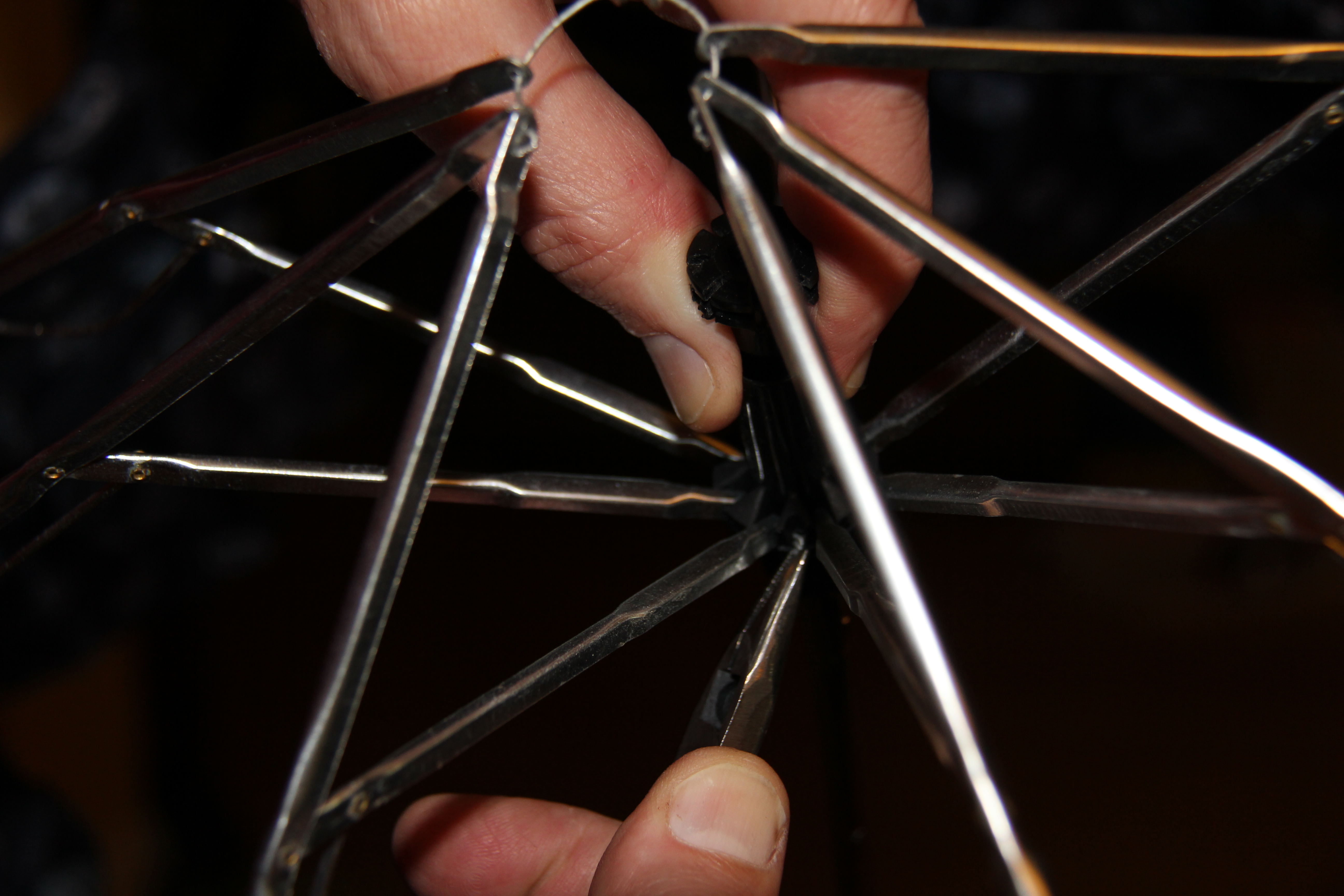
Now, we don't want someone to fart on your hand! Hot glue the top side of the tin (the side that does not have the methane sensor and the rocker switch) to a long wooden stick or the end of a torn down umbrella. If you don't have a long wooden stick of some sort, go buy an umbrella for $3 at Walmart. That's what I did. There are some pictures up above of the meltdown of the umbrella.
Farting Finale!

Now plug in the 850mAh LiPo into the Lilypad Power Supply in the hat. Flip on both of the switches and start farting! It's hilarious! Thank you for looking at my instructable. If you like this, please subscribe.