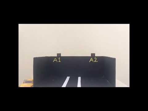
Garage With Pinoo
Project Purpose: To make a garage project by using Ldr and led modules with Pinoo control card.
Duration: 2 lessons
Age Group: 9 years and older
Pinoo Set: Basic, Invention,Maker,Full Set.
Benefits:
• Learns to code Pinoo control card.
• Learns to use a LED module.
• Learns to use the Ldr module.
• Improves the skill of setting up algorithms.
• Improves coding skill.
Supplies
Required Materials: Mblock 3 program, Pinoo control card, 2 led modules, 2 ldr modules
Materials Required for Design: Shoe box, black cardboard, felt-tip pen, scissors and a utility knife, A-4 paper, silicone gun and silicone.
Project Preparation
- For our project, let's start by designing the garage first.
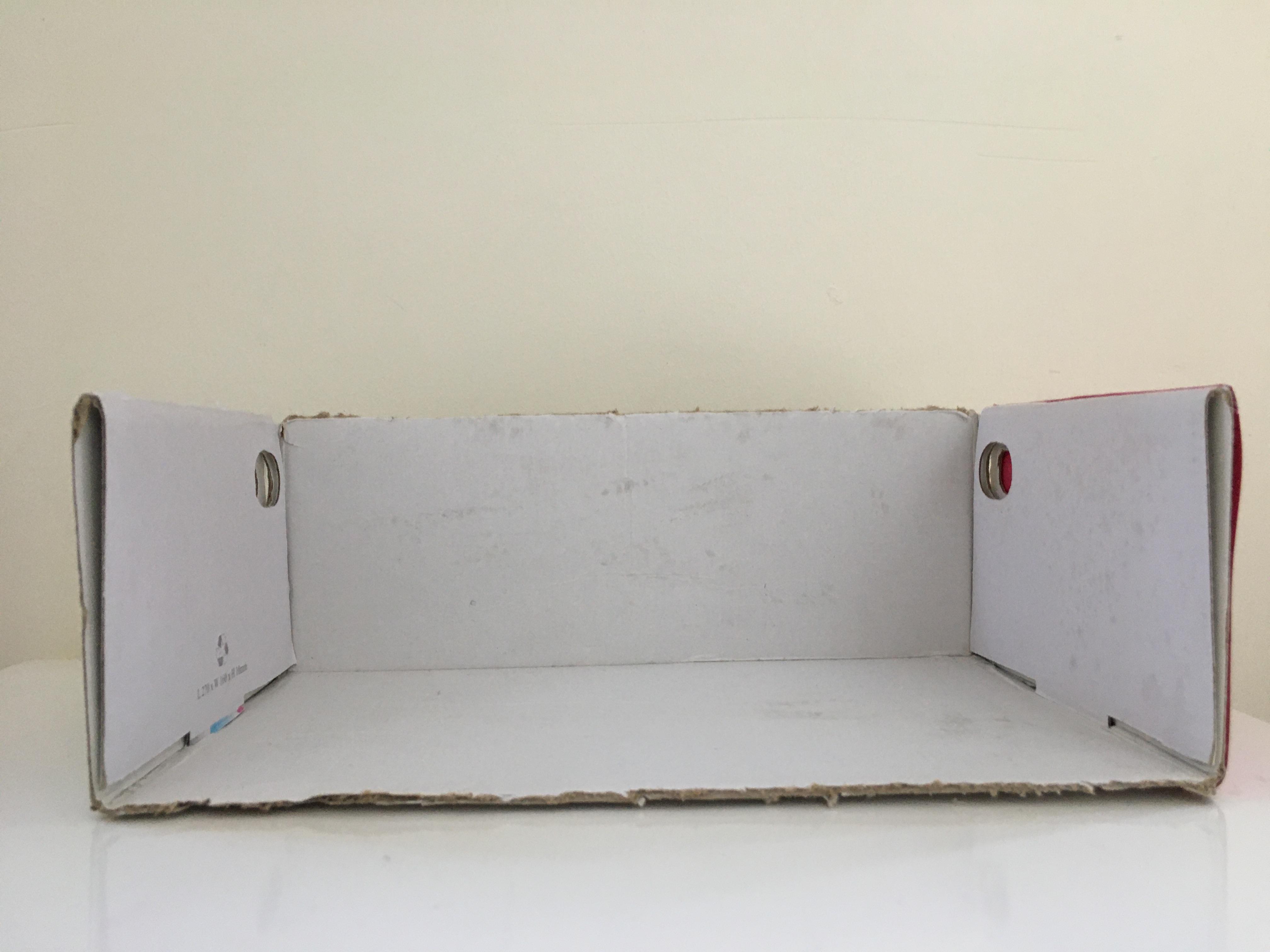
- We cut the cap and top of the box.
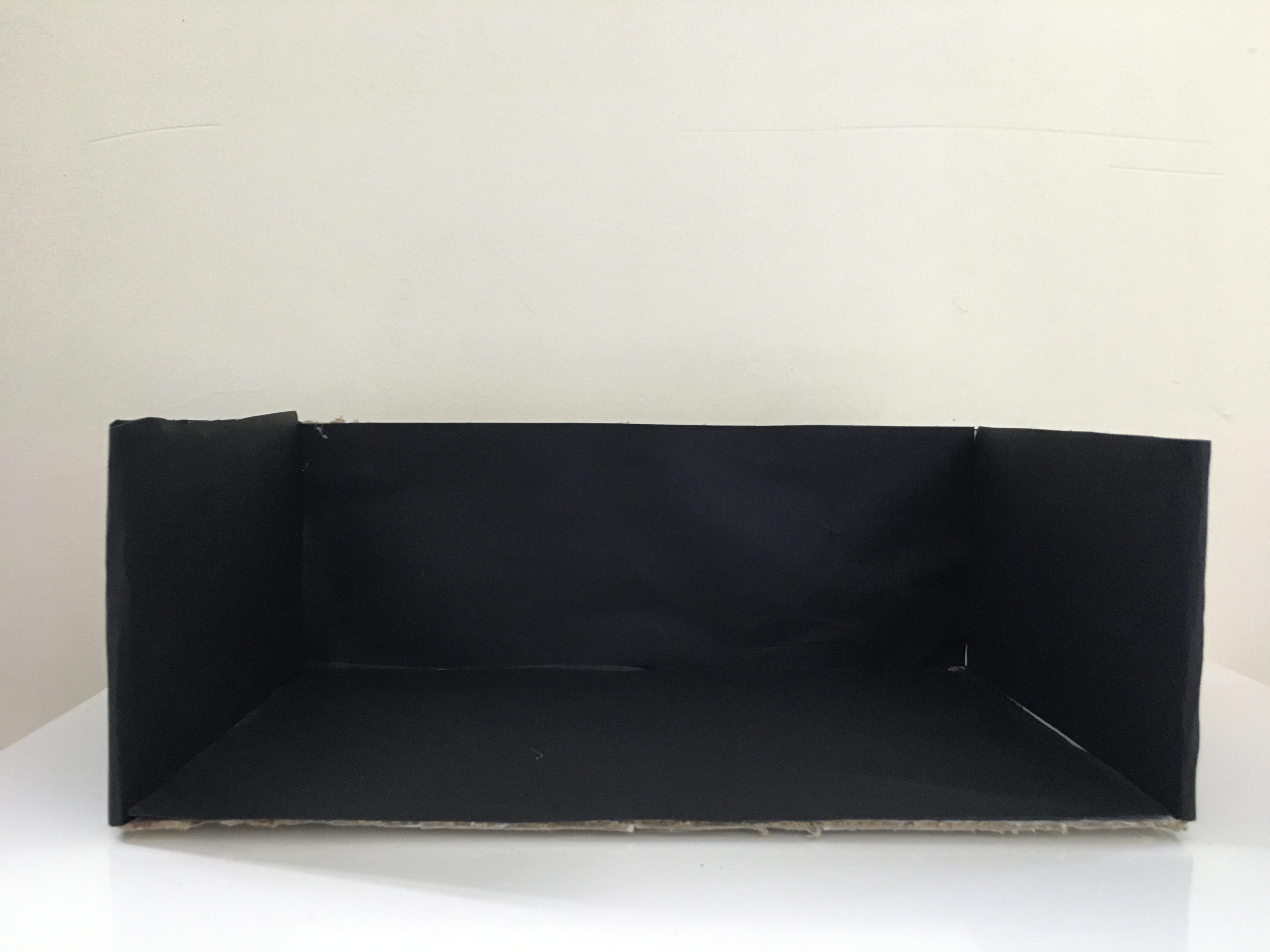
- We cover the box with black cardboard and silicone.
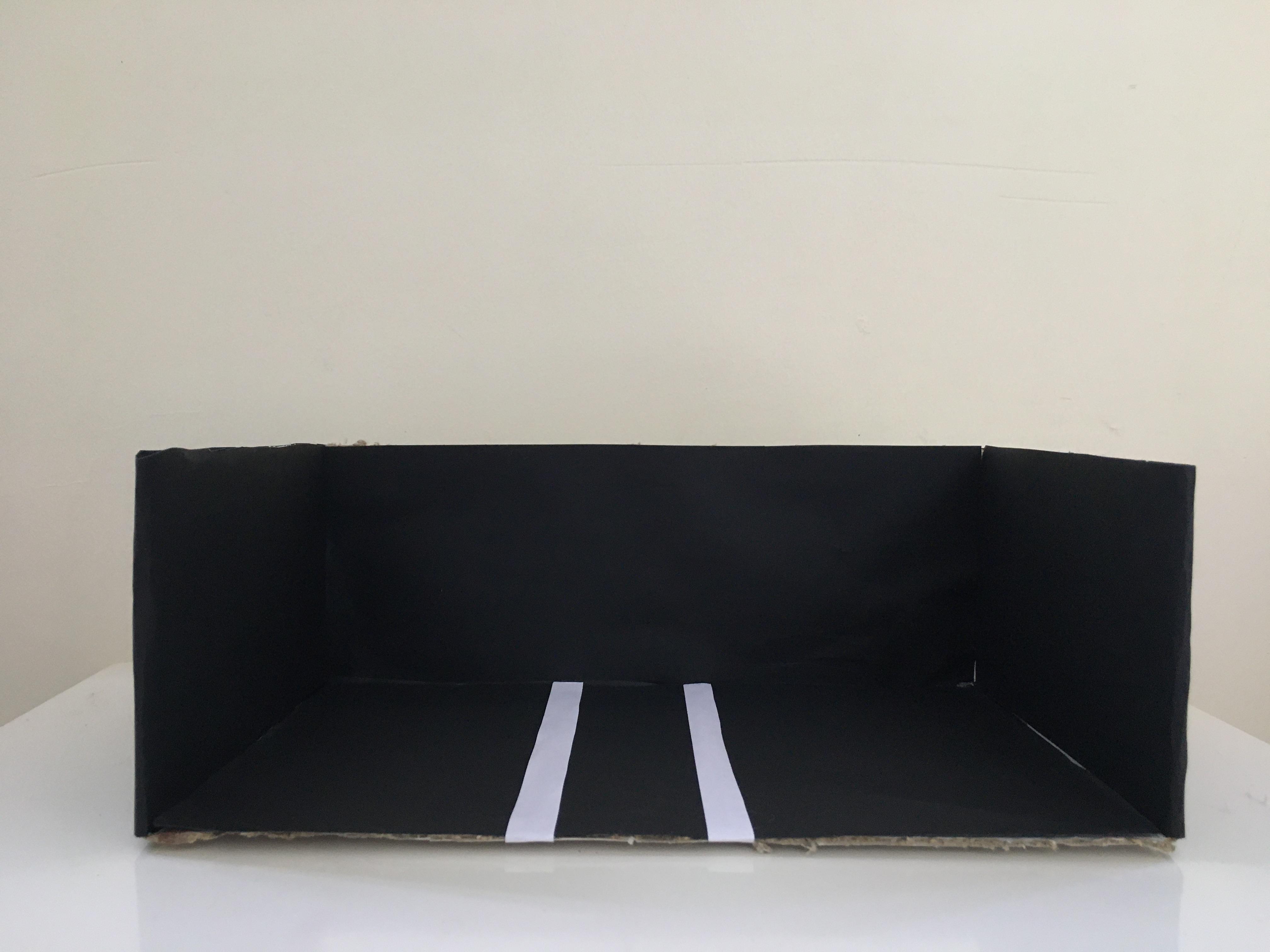
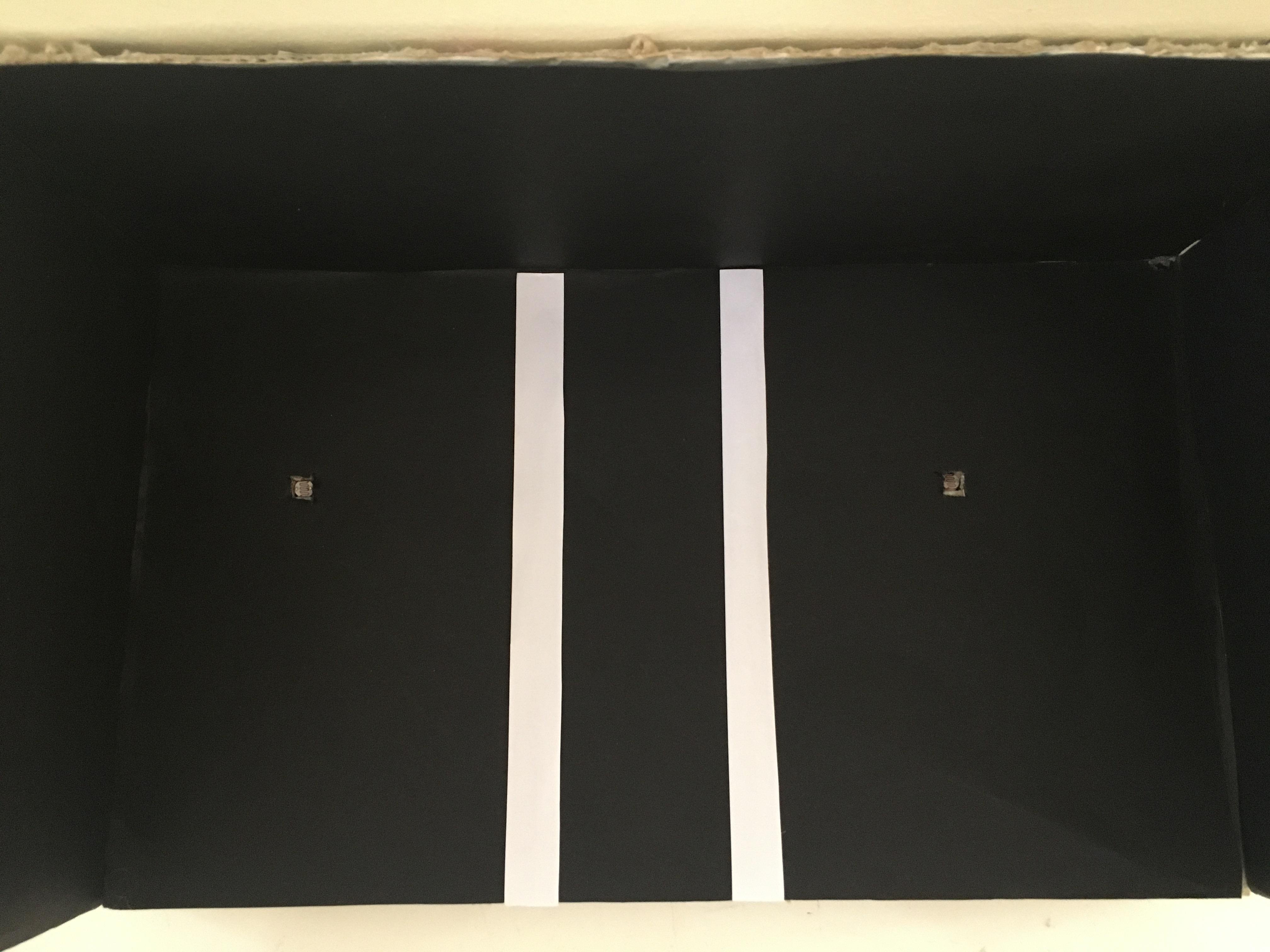
- We cut 2 strips from A4 paper and stick them on the floor of the box. (To indicate vehicle fields)
- With the utility knife, we create two spaces large enough for the ldr module to enter.
- We silicon the Ldr modules into the spaces we create.
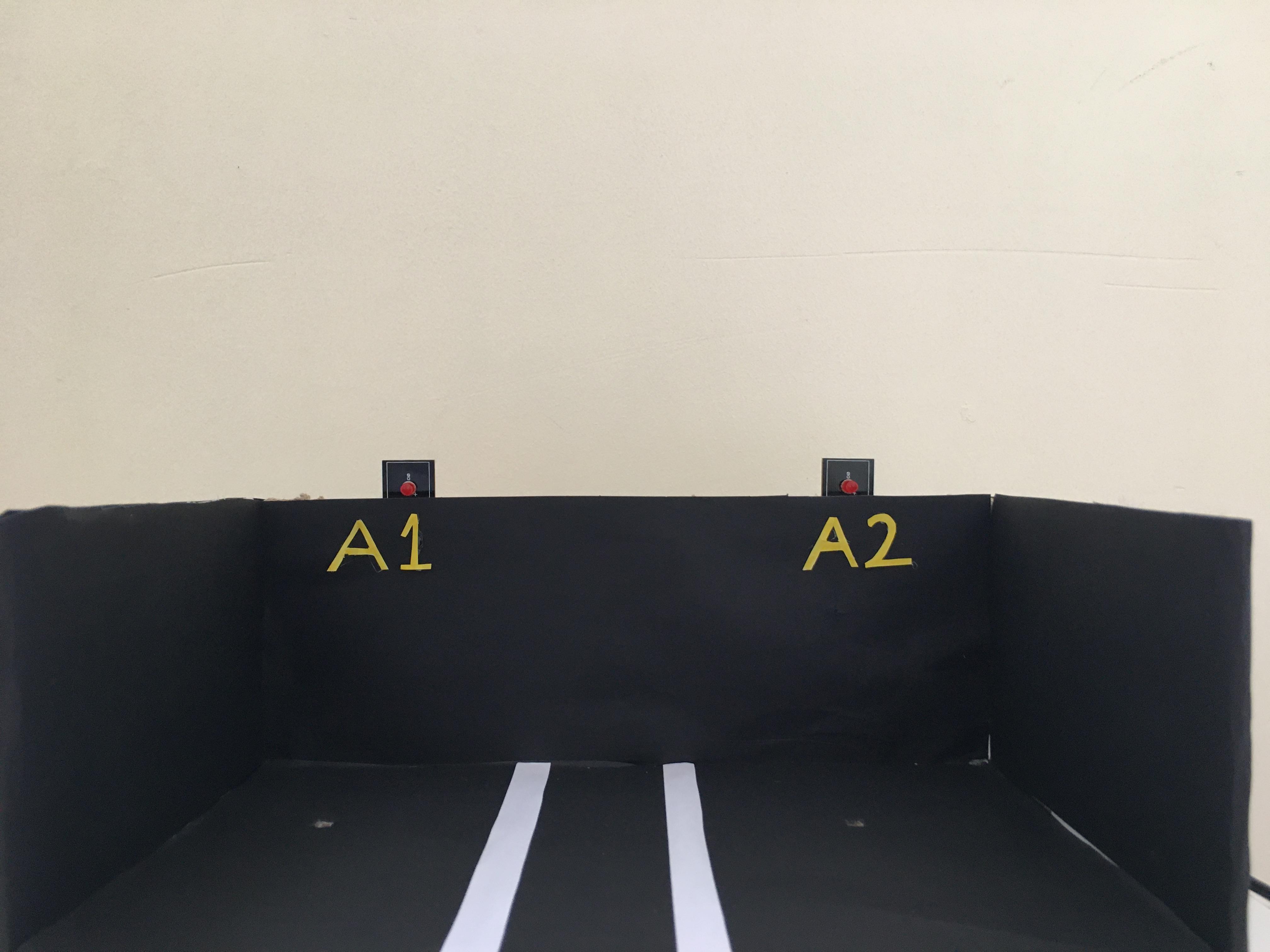
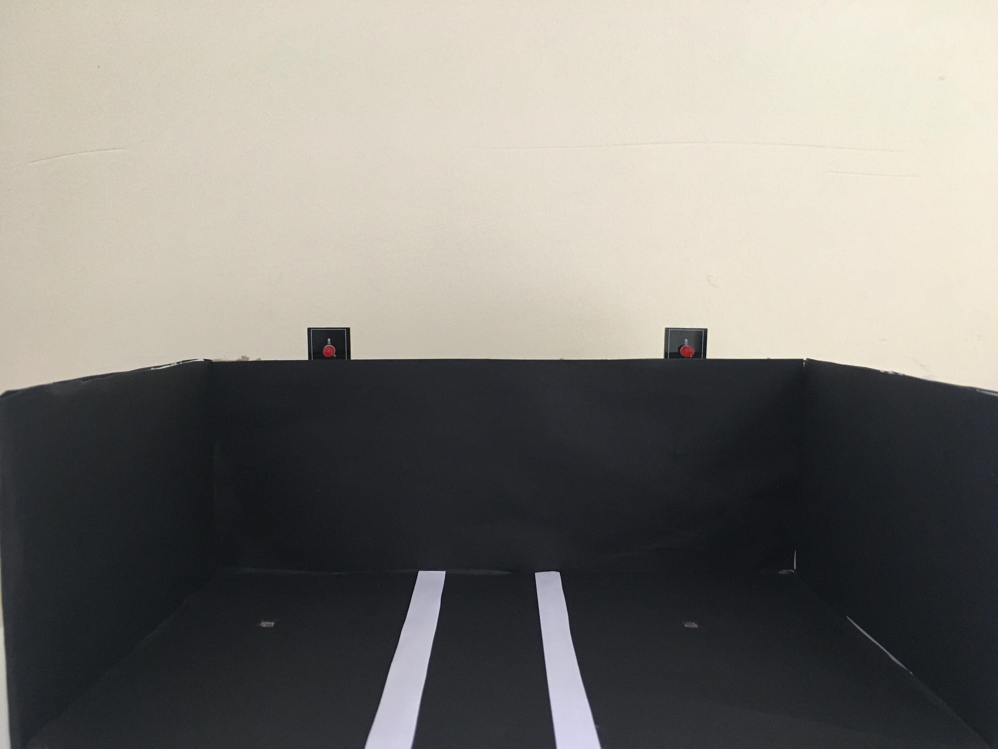
- We silicon the LED modules at the top of the box parallel to the Ldr modules.
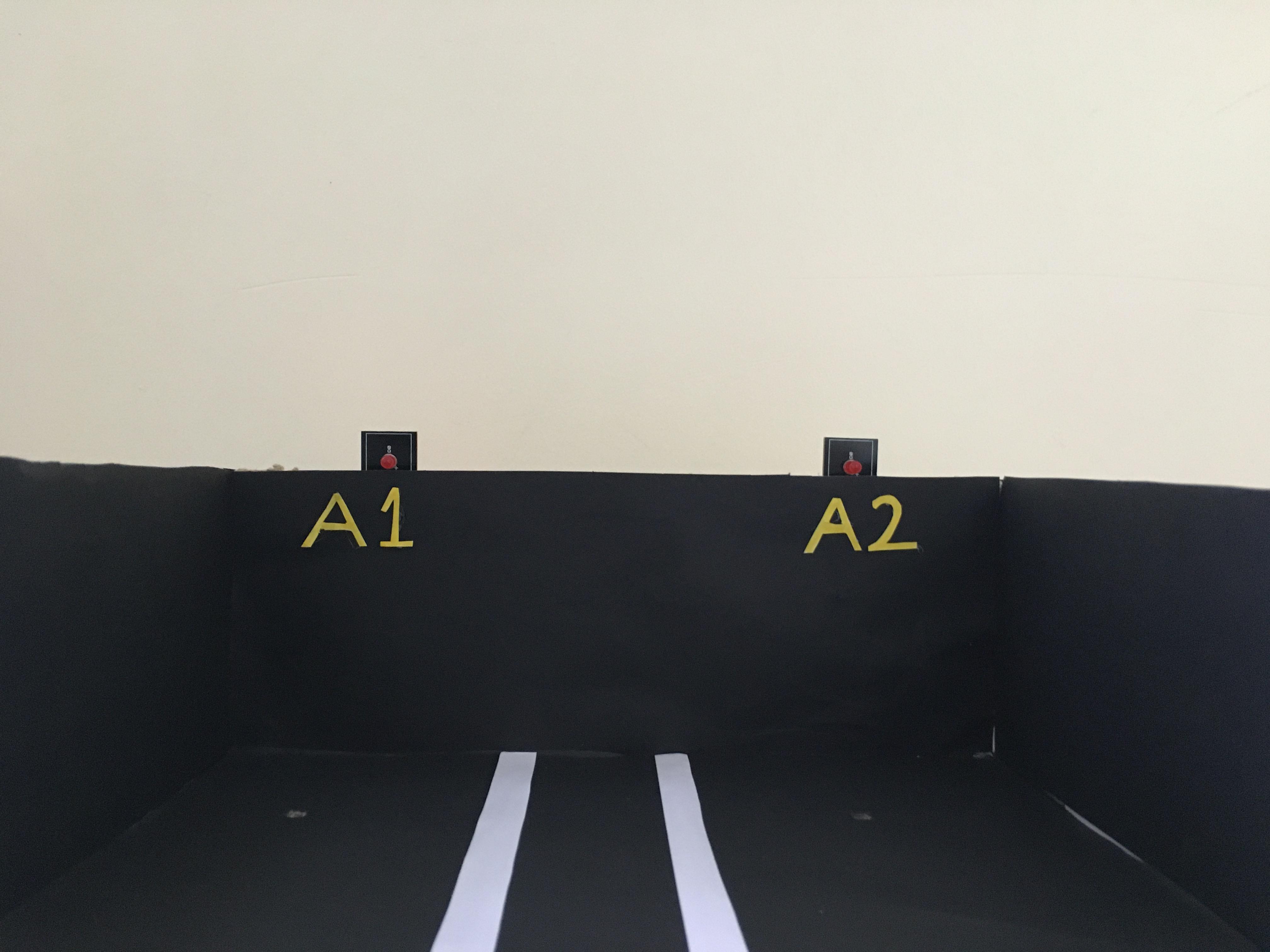
- We write "A1-A2" on A4 paper with a felt-tip pen and then cut it with scissors. We use the texts we cut to number the parking spaces.
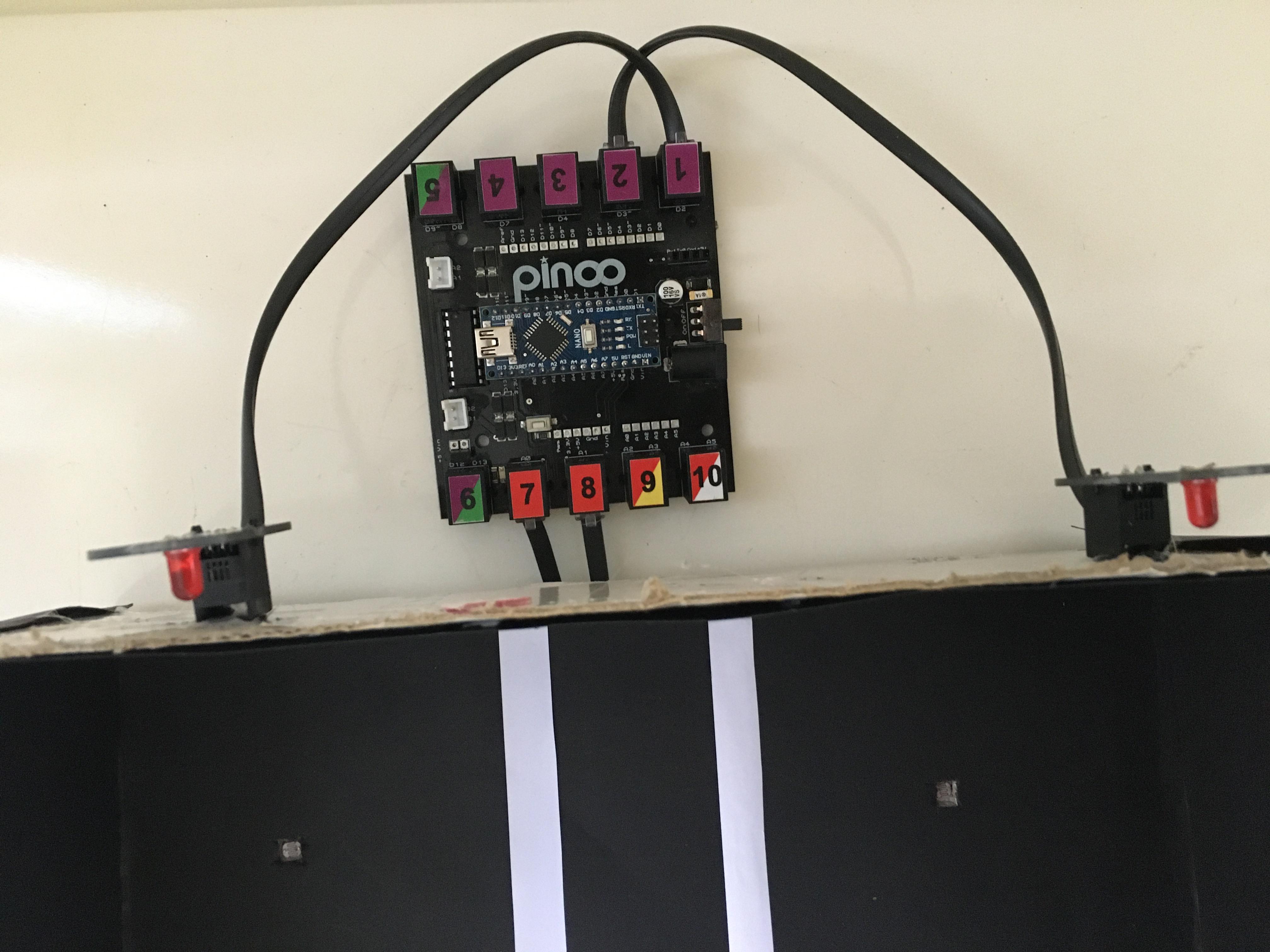
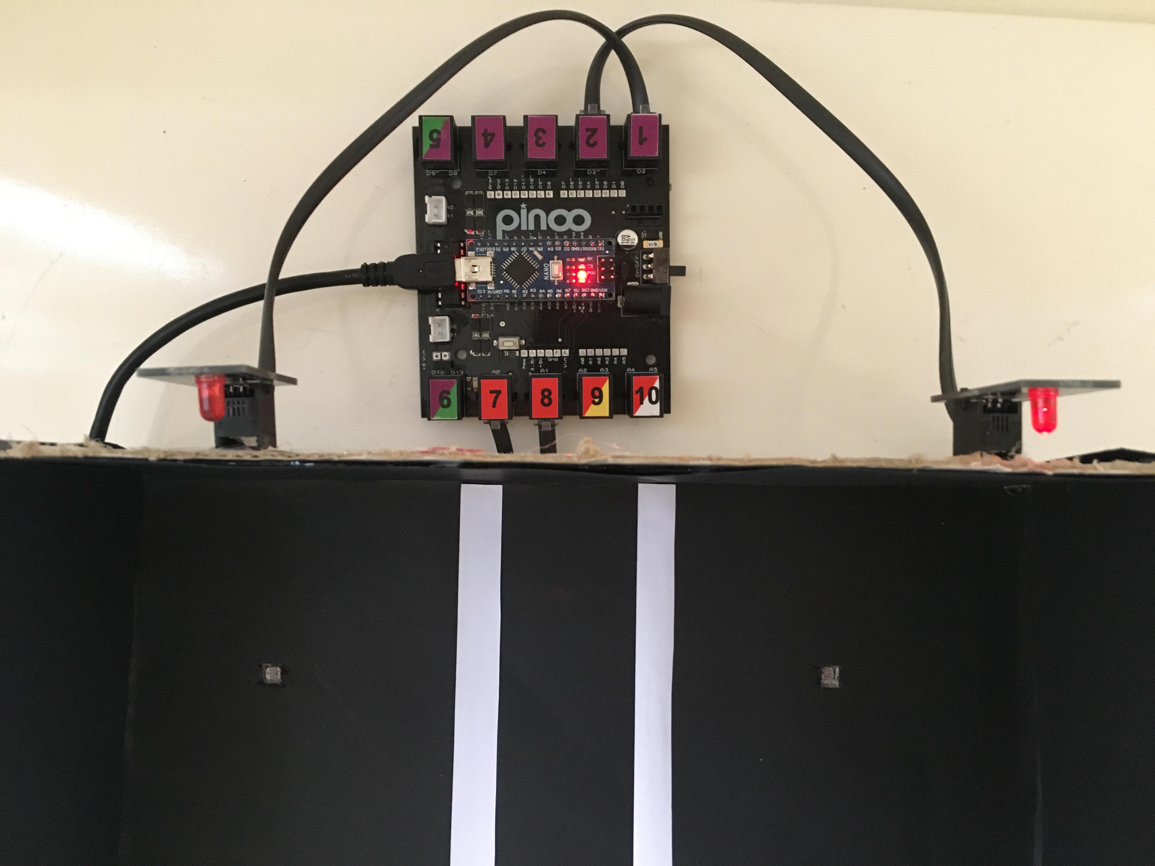
- We install the connection cables of the Ldr and led modules. (You can pay attention to the parallel connection here. For example, for the ldr module installed on the 7th door, I associated the led module on the 1st door. 8. For the ldr module installed on the door, I associated the led module on the 2nd door.
- We plug in the USB connection cable. Now we can start coding.
- All electronic parts in place
Adding Pinoo Extension
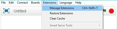
- From the ‘’Extensions’’ tab, we click on the "Manage Extensions" option.
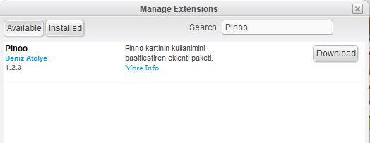
- In the window that opens, we type "Pinoo" into the search engine and simply say download to the result. It was installed on our computer.
Connecting the Pinoo Control Board to the Computer
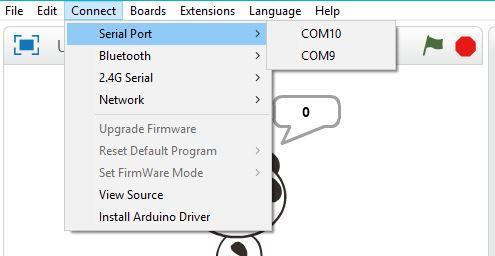
- In Mblock 3, we click on the "Connect" tab on the upper left.
- We click on the "Serial Port" section from the window that opens and select the "COM6" option from the page that opens. NOTE: Since the port entries of each computer are different, the numbers next to the COM text may change.
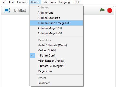
- We click on the ‘’Cards’’ tab.
- We select the "Arduino Nano" card option used by the Pinoo control card from the window that opens.
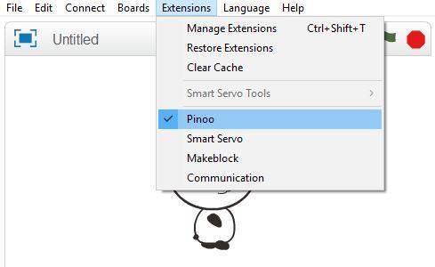
- We click on the ‘’Extensions’’ tab.
- In the window that opens, we select the extension "Pinoo" of the control card we are using.
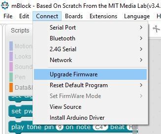
- We click on the ‘’Connect’’ tab.
- We click on "Firmware Update" from the window that opens.
Coding Part


- First, when we click the green flag, we are coding to see the light value on the screen.
- (In this section, let's determine the light and dark values by covering the ldr module with your hand. The ldr value attached to the 8. door will read the same values, you can try.)
- If not, we add the condition structure and create our first condition for the ldr module connected to the 7th gate. (Here we used a value of 150, which is a general value close to the dark one.)
- If the condition is true, that is, if it is dark, we turn on the LED module connected to the door. If not, we put it out. For our other condition, if not, we add the condition structure and create our second condition for the ldr module connected to the 8th gate. (Here we used a value of 150, which is a general value close to the dark one.)
- If the condition is true, that is, if it is dark, we turn on the LED module connected to the second door. If not, we put it out.
- In order to upload our codes to the Pinoo sensor card, we make the "Pinoo Program" command at the beginning of the event and delete the code we use to see the button value on the screen.
- We right click on the "Pinoo Program" command and select the "Upload to Arduino" option in the window that opens. On the page that opens, we click the "Upload to Arduino" button selected in red.
- Our codes are uploaded to our Pinoo control card.
- We click on the "Close" button after the "Download Finished" text appears.
Working Status of the Project
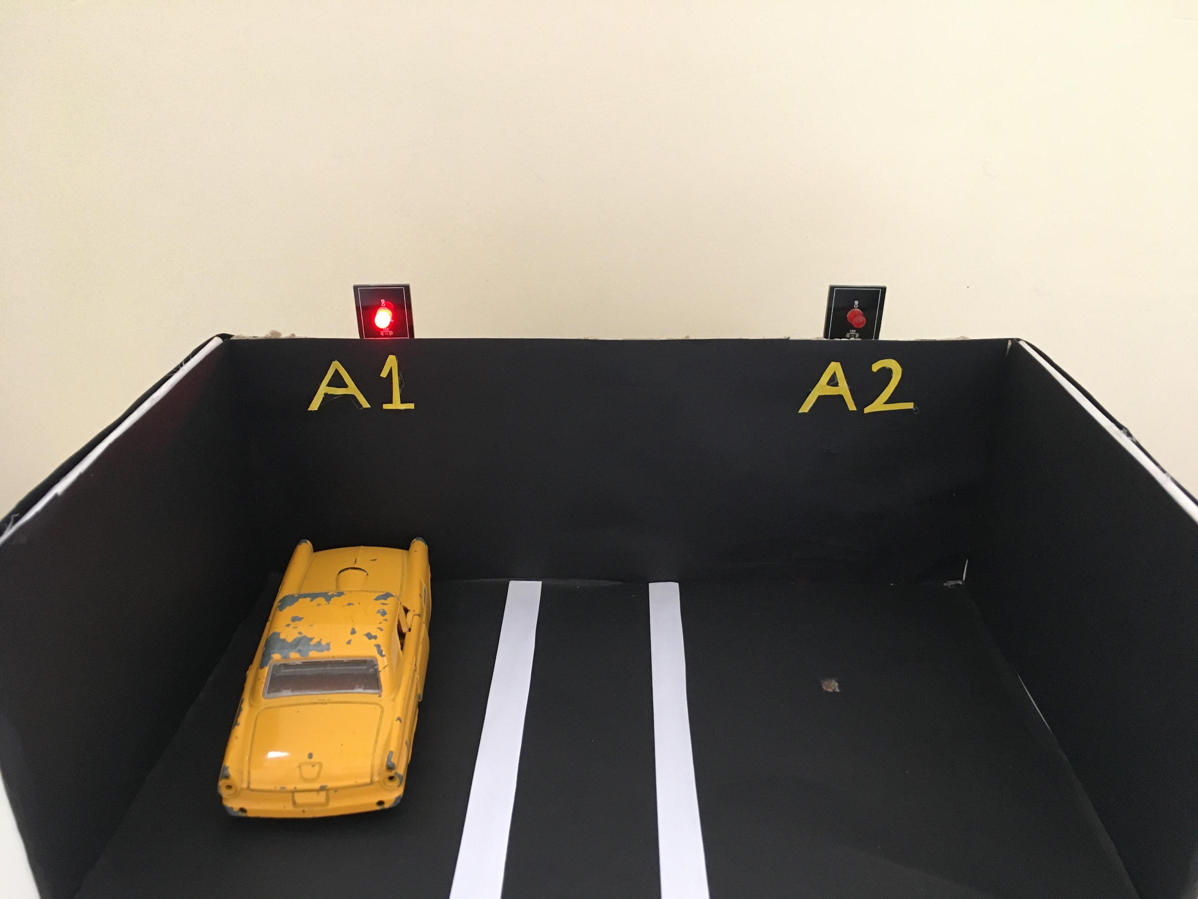
- We are installing the 9V battery.
- We put the car in the parking lot.