Gamma Waves Light for Brain Stimulation and (hope) Alzheimer Non Invasive Therapy
by OPagliarulo in Circuits > Arduino
976 Views, 1 Favorites, 0 Comments
Gamma Waves Light for Brain Stimulation and (hope) Alzheimer Non Invasive Therapy
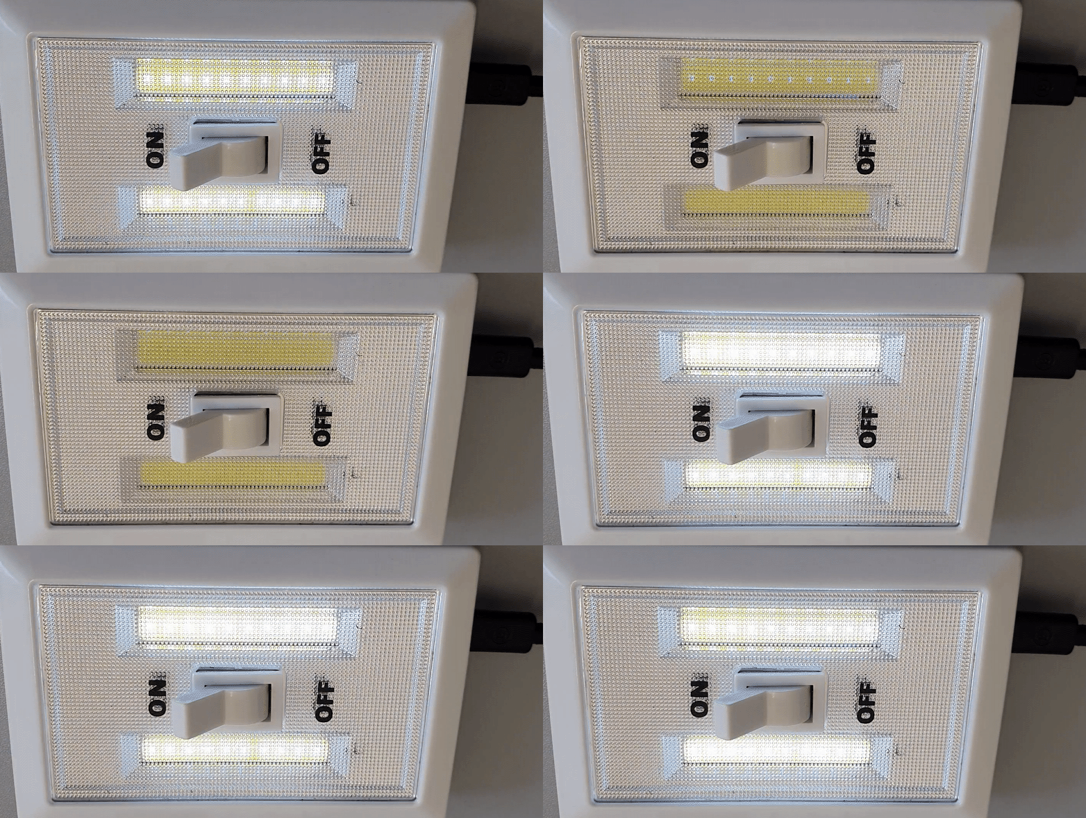
Gamma Brain Waves are known to be generated in our brain during high levels of functions like cognition and memory. From recent studies it seems that stimulating the brain with light and/or sound tuned on these frequencies helps to improve memory, learning and information processing.
https://en.wikipedia.org/wiki/Gamma_wave
https://news.mit.edu/2016/visual-stimulation-treatment-alzheimer-1207
In this Instructable I will show you how to modify a cheap LED lamp to build a simple but fully featured experimental Gamma Brain Waves Light.
I wrote the firmware we are goin to use in this Gamma Waves Light some time ago for a slightly complex project, it's for ESP8266 based devices and has many features like:
- Programmable light flickering frequency (1-100 Hz)
- Programmable light brightness
- Wifi reachable (STA and AP mode)
- Complete control and configuration by web
- Firmware update by web
- Audio output for generating sound
You can download the source code from GitHub here:40HzGen
Note: Execute all the steps in the right order! Do not connect the device to your PC USB port if the COB LED is connected to the circuit! If you use high current LEDs it may damage your PC USB Port, load the firmware into the Wemo module before connecting the power module and the COB LED.
⚠️ Warning:This device will flash/strobe the light! Don't use it next to individuals with epilepsy!
⚠️ The research has not been tested and has not been proven to work on humans! Use it at your own risk!
Supplies
.jpg)
Hardware required:
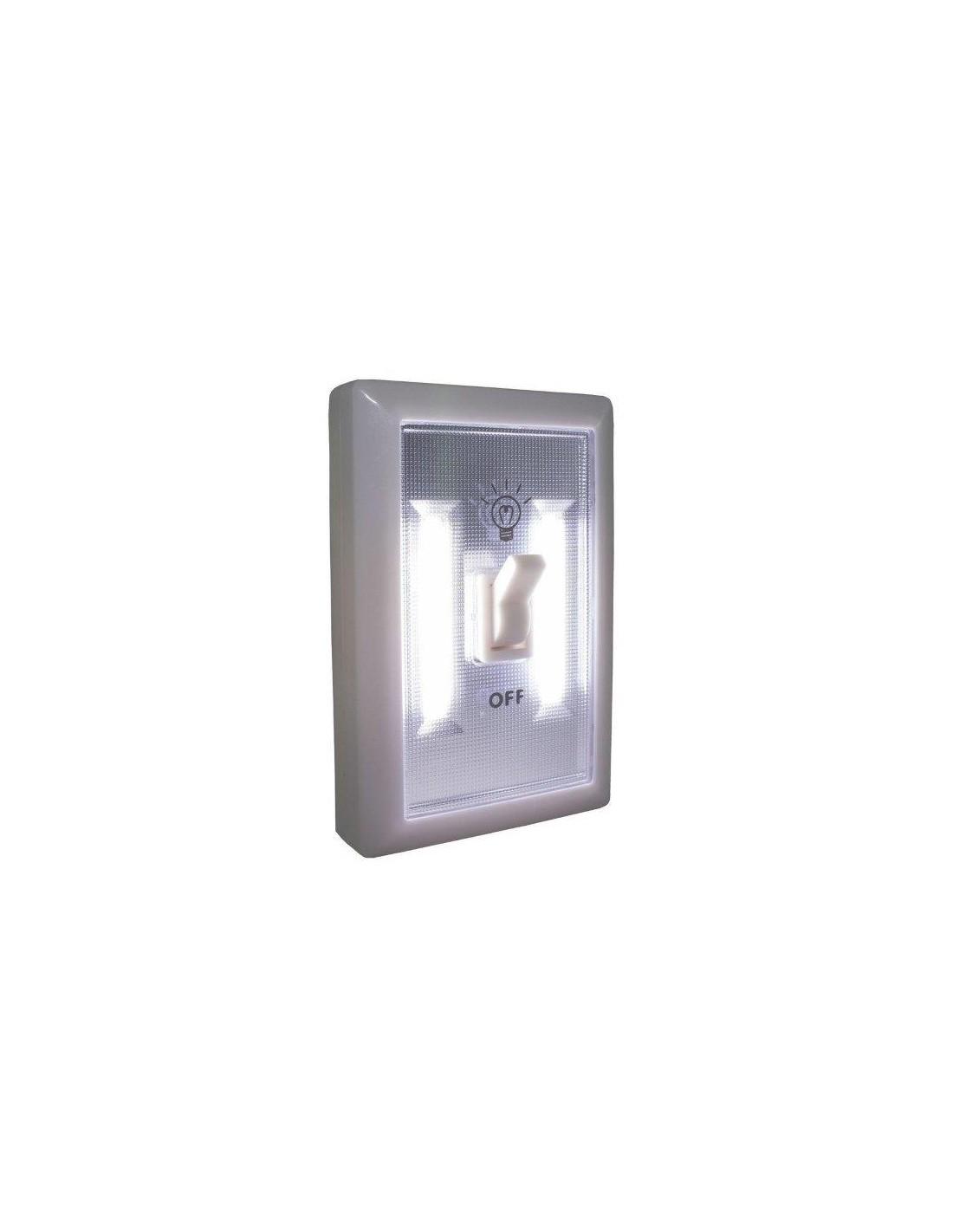
- This COB Led Lamp or similar (3€ approx)
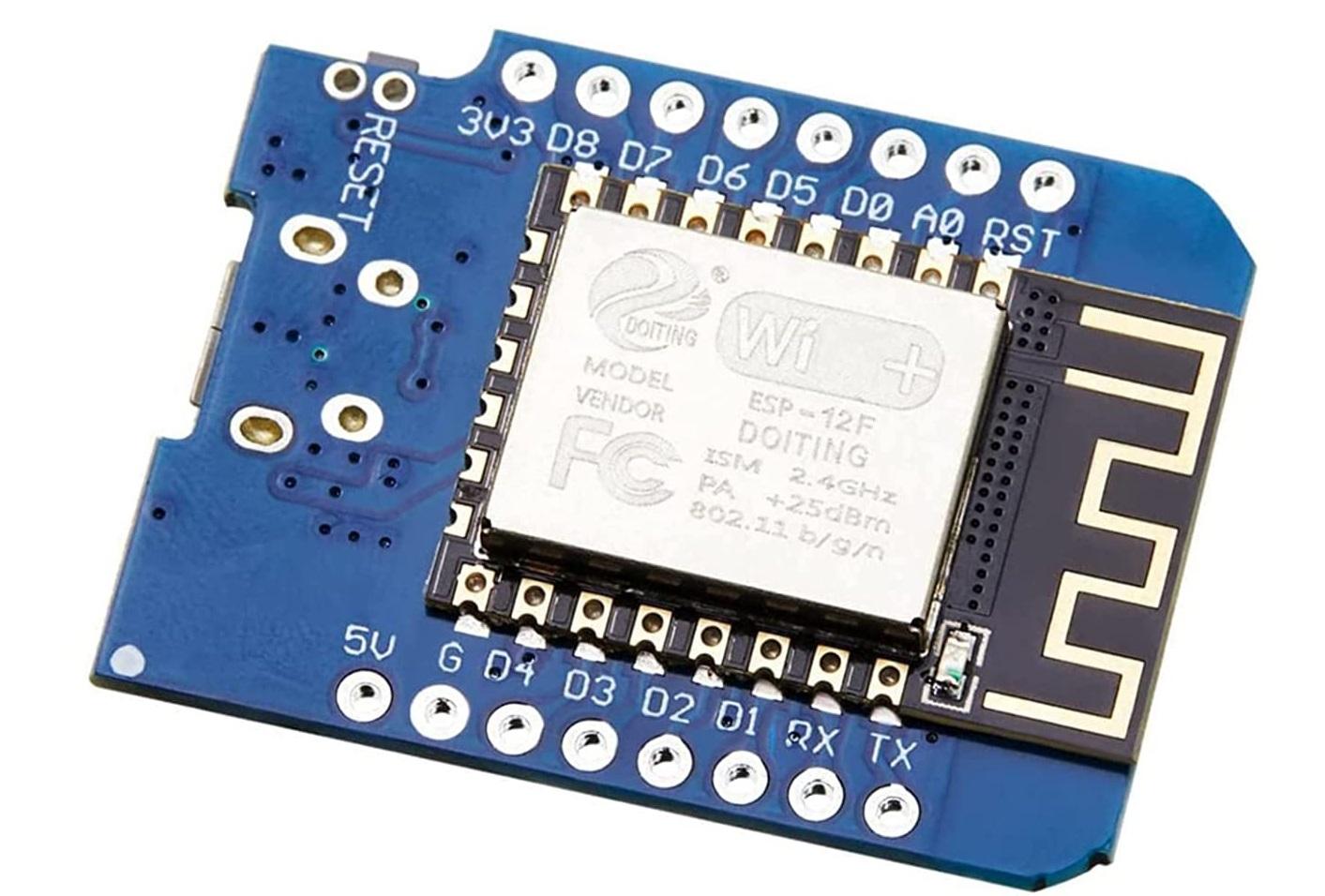
- Wemos D1 Mini (9€ approx)
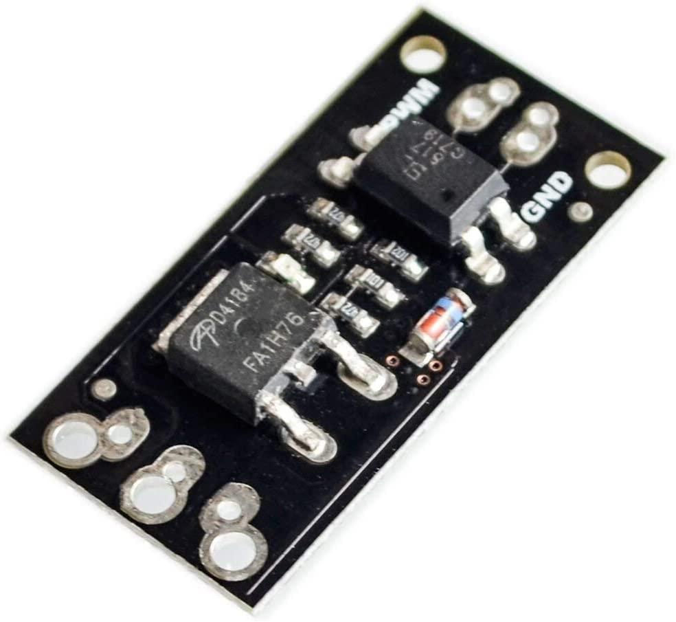
- D4184 Mosfet Power Module (2€ approx)
- 2000mA MicroUSB phone charger
- Some wire
Tools required:
- Soldering iron
- Cutter
- Hot Glue Gun
- Pliers
- Screwdriver
Loading the Firmware
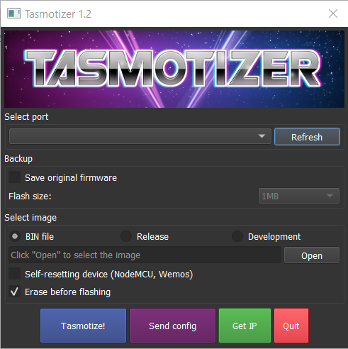
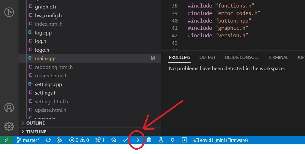
Connect the Wemos D1 Mini to your PC through the USB cable and flash the Wemos choosing one of the methods below.
Method 1: (the easy way)
Download the binary file from here:firmware-D1-Mini_noLCD.bin
Download Tasmotizer from here:Tasmotizer
In the Tasmotizer window:
- Select the COM port of the Wemo
- Click on the 'Open' Button and select the binary file
- Click on the 'Tasmotize!' Button to flash the device
Or
Method 2: (for those who already have VSC and PlatformIO installed on PC)
If you want to build the firmware from the source code you need Visual Studio Code and PlatformIO installed on your PC
- Download the code from my repository here:40HzGen and unzip it
- In VSC open the folder where you placed the unzipped source files, PlatformIO should start
- Select the env d1_mini
- Build the code (downloading some libraries could start, wait for the end..)
- When build is completed you will be able to flash the chip clicking on the right arrow at the bottom of the VSC window.
Preparing the Hardware
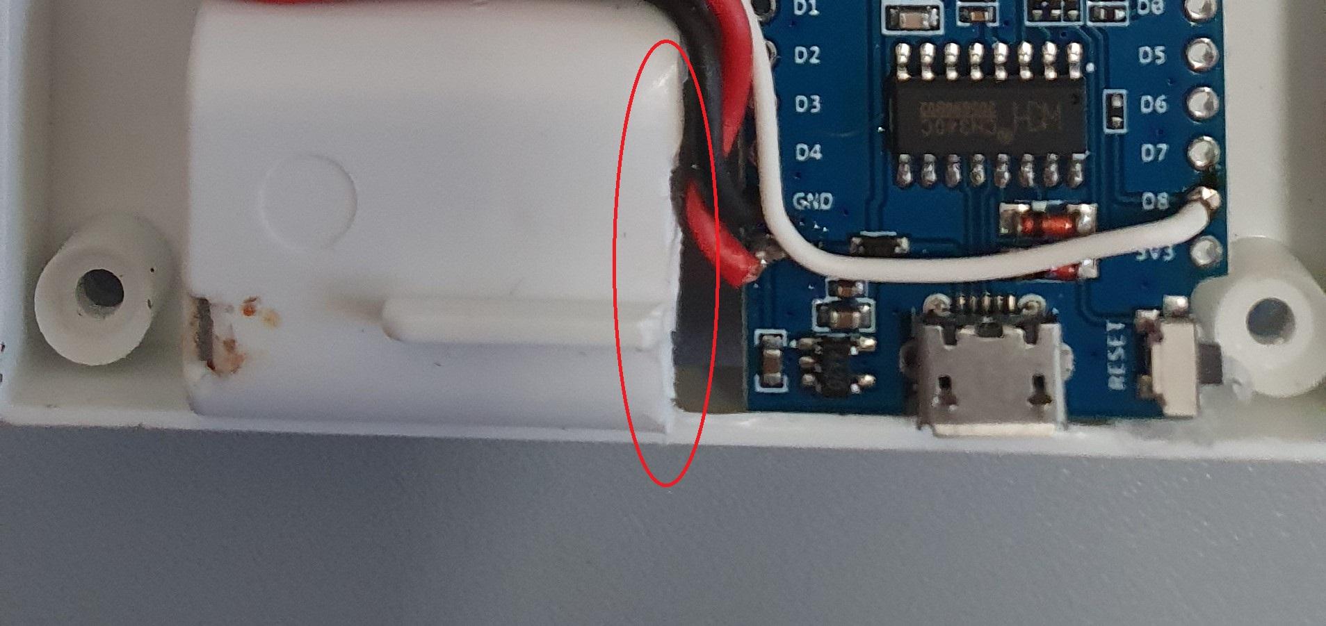
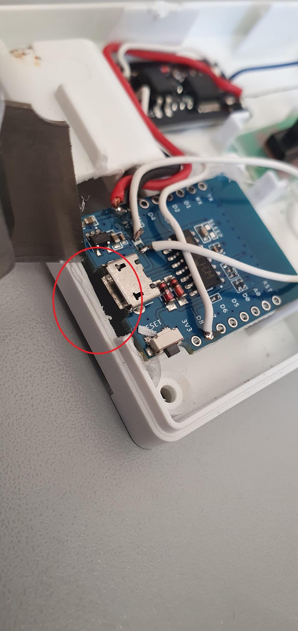
- Remove all the screws on the bottom side of the lamp
- Open the enclosure
- Use the soldering iron to diconnect all the wires from the battery contacts (we don't need batteries) and from the Power Switch
- Use the cutter to remove part of the lower battery housing to make space for the Wemos D1 Mini module
- Make a little window at the bottom for the USB connector
- Use the hot glue to fix the Wemos module and the D4184 mosfet module.
Wiring the Modules
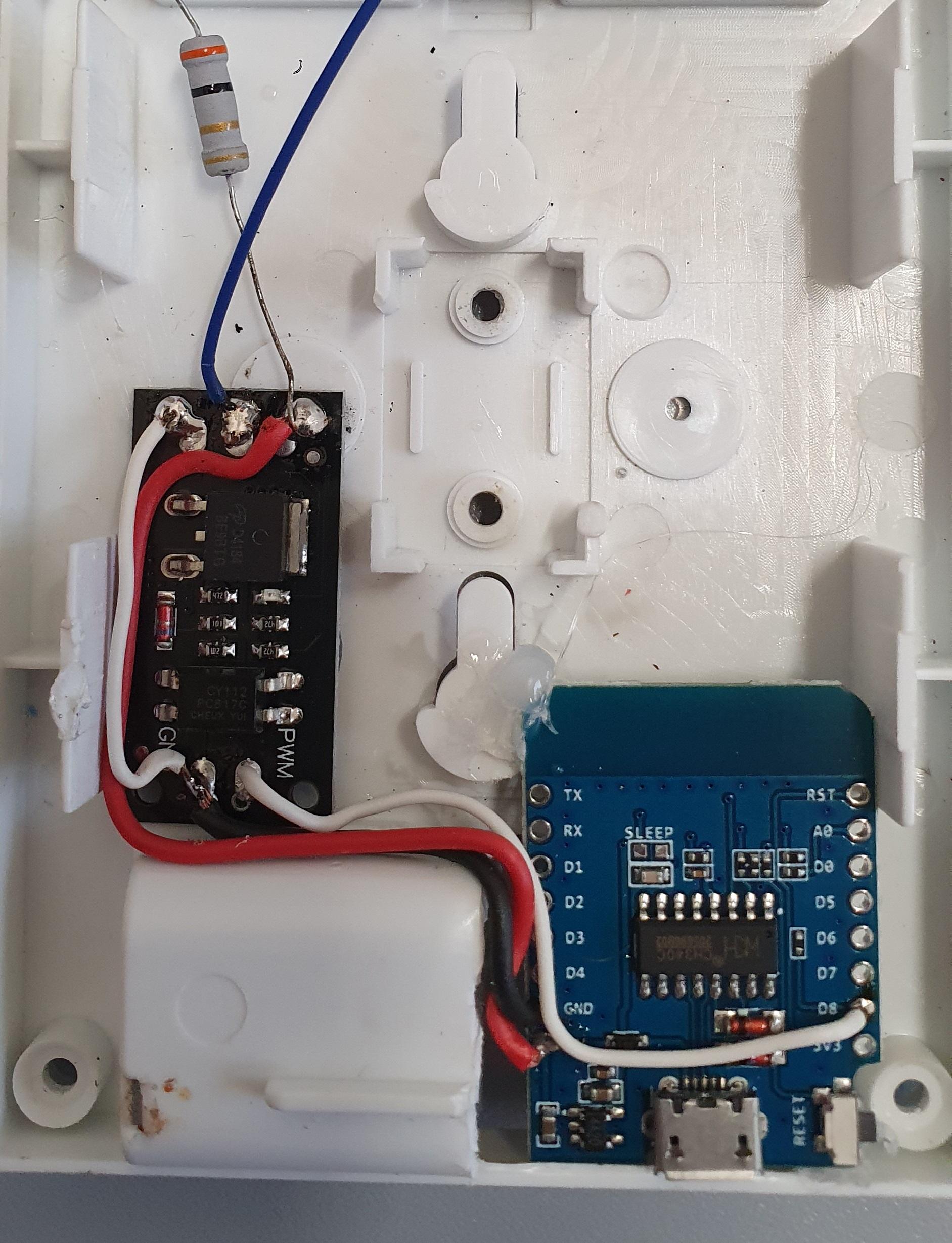
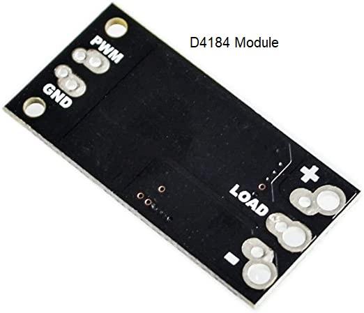
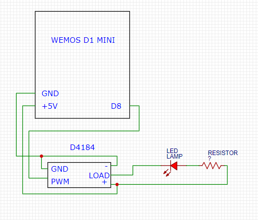
Use the Soldering Iron and some wire to:
- Connect the D1 Mini +5V pin to the + pin on the D4184 Module
- Connect the - pin to the GND pin on the D4184 Module
- Connect the D1 Mini GND pin to the GND pin on the D4184 Module
- Connect the D1 Mini D8 pin to the PWM pin on the D4184 Module
- Connect the existing resistor coming from the positive of the LEDs to the + pin of the D4184 Module
- Connect the negative wire of the LEDs to the LOAD pin of the D4184 Module
The Power Switch (Optional)
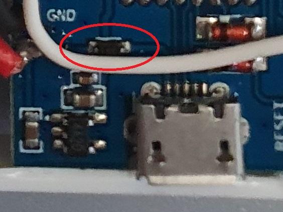
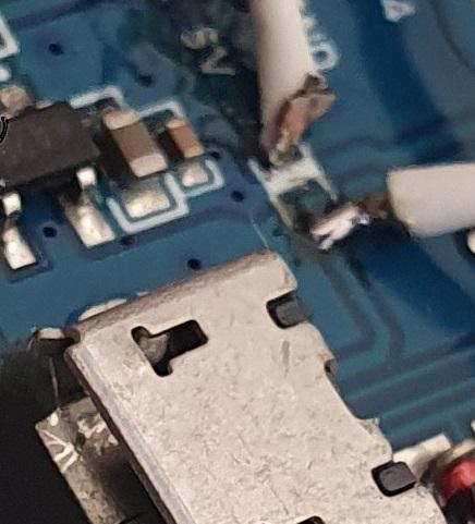
If you want to use the power switch of the lamp to power On and Off the device:
Be careful here, you need some SMD soldering skills...
- Remove the SMD diode placed between the +5V pin and the USB connector of the D1 Mini
- Connect the two wires from the power switch to the two pads of the removed diode.
Remounting the Unit
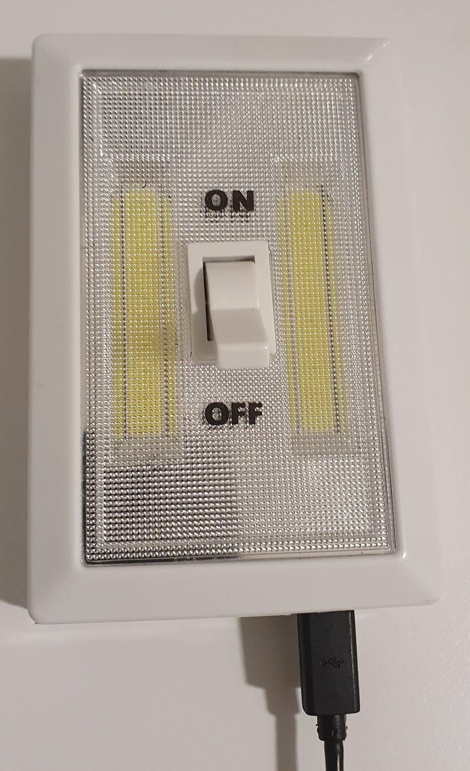
Double check all the connections, if everithing is right put the COB LED in place, mount the cover and the Power Switch lever.
Setting Up the Device
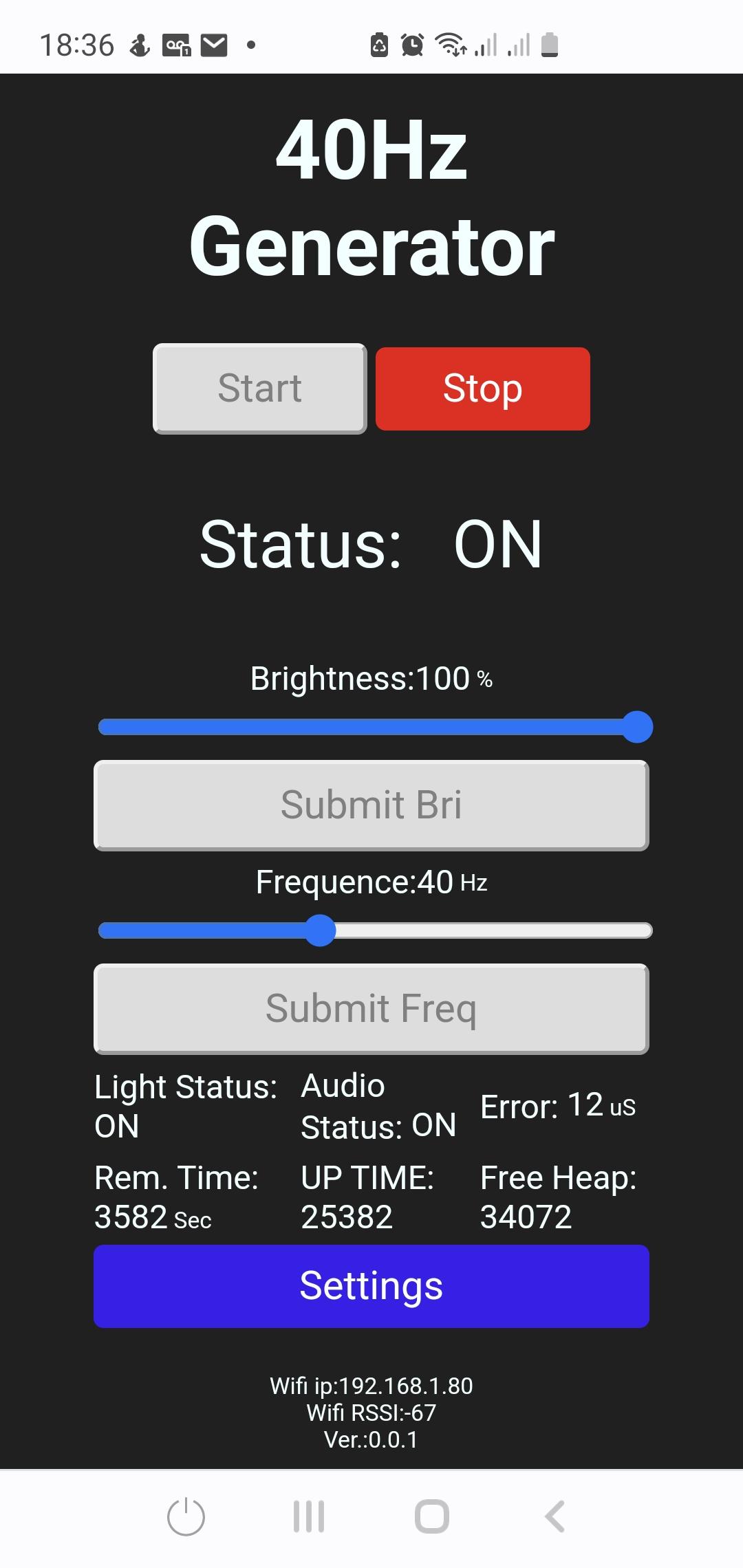
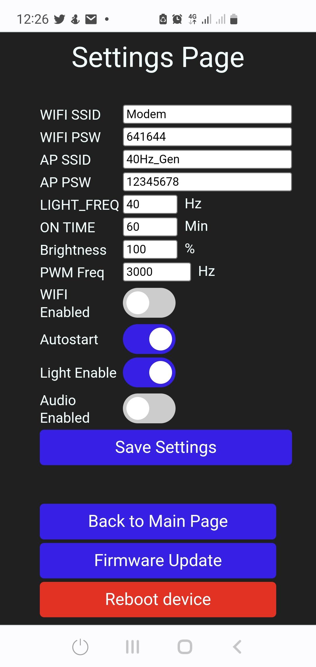
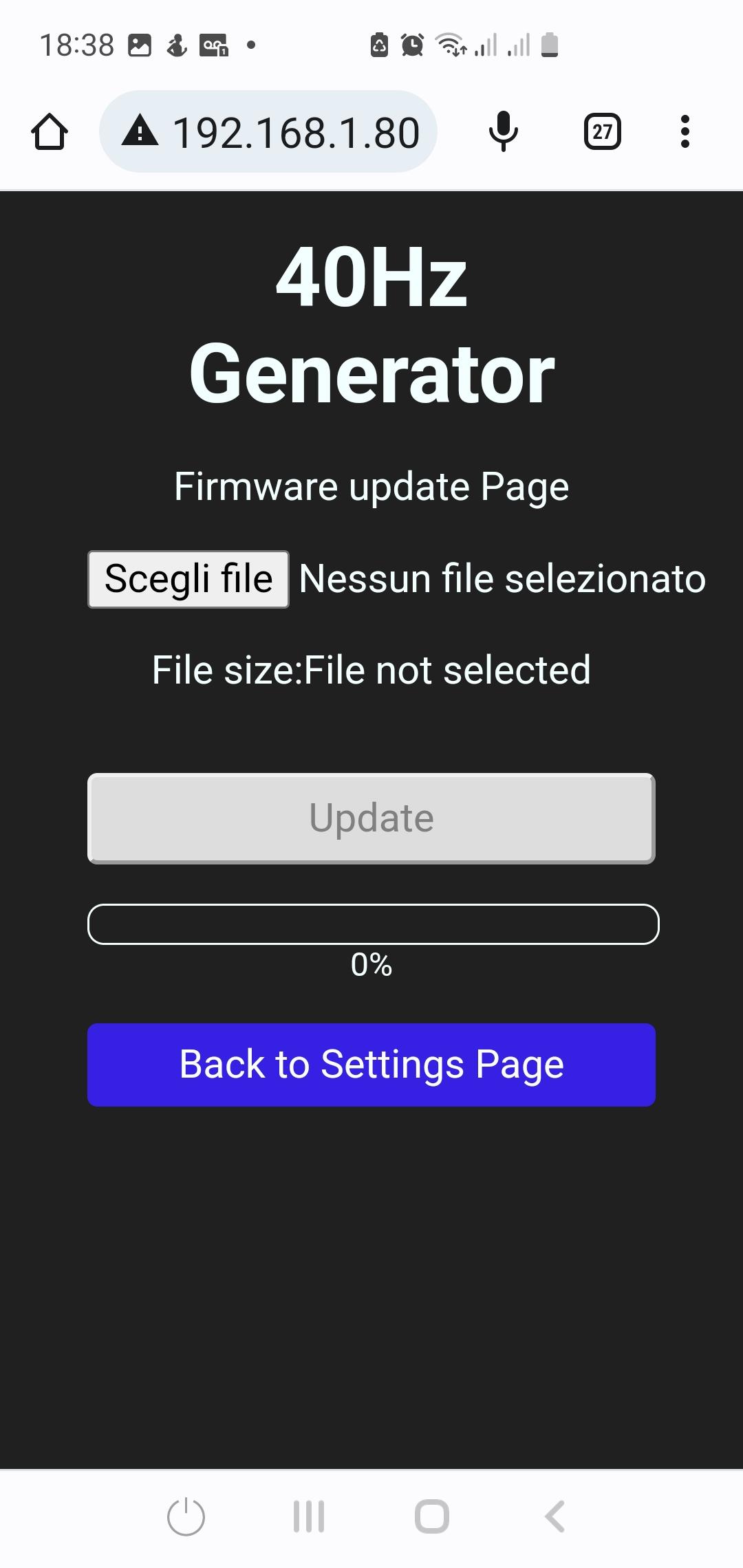
Well, now it's time to play with the settings and test your new Gamma Light...
- Plug the Phone charger and power on the device, it will not light on immediately, don't worry...
- With your smartphone or you PC search for new Wifi networks, you should find one named 40Hz_gen, the password is 12345678
- Open the browser and insert the ip address 192.168.16.4
- You should see the main page of the device, click on the 'Settings' button, the Settings page should load
- If you want the light to connect to your home wifi network enter the SSID, the Password and switch on the 'Wifi Enabled' button
- Leave the AP SSID and AP Password settings to the default
- Set the 'LIGHT_FREQ' field to 40 Hz
- Enter in the 'On Time' field the minutes you want the light will be flashing
- Set the 'Brightness' field to 100%
- If you want the light starts flashing on every power-on set the 'Autostart' button ON
- Check the 'Light Enable' button is ON
- Check the 'Audio Enable' button is OFF
- Click on the 'Save Settings' Button. The device will restart...
If you enabled the wifi setting, now and every time you switch on the device it will first try to connect to the wifi, it takes a few seconds, and then, if you enabled the autostart function, the light will start flashing.
Final Considerations
If your COB LEDs are not 5 Volts and need a different voltage (eg 12V or any other) you can connect an external power supply to the D4184 Module in this way:
- Don't connect the wire 1 and 2 in the wiring instructions
- Connect the external power supply to the - and + pin of the D4184 module
If you prefer you can add a push button connected to the D5 pin and GND pin of the Wemos D1 Mini, this button can be used to START and STOP the flashing time right on the device insted of using the smartphone or the power-on autostart function.