Gamepad Using Arduino
by BharathRam in Circuits > Microcontrollers
2762 Views, 17 Favorites, 0 Comments
Gamepad Using Arduino

In this instructable I will show you how to make a simple game pad(joy stick) using microcontroller,few buttons and a visual basic application for playing subway surfers in PC....
I will guide you step by step using simple construction parts. Remember this tutorial is to help you out and for you to have an idea on how to make your own gamepad, using this one as an example
Materials and Software

Here is the list in no particular order of the parts, tools and software needed for this project.
Parts:
1)PIC18F4520 or arduino (i used a PIC development board, u can use any microcontroller)
2)Four push buttons.
3)4 resistors or resistor pack.
4)some wires
Note: if u have arduino u can skip following steps.......
5)20Mhz crystal and two 22pf capacitors
6)5 volt power supply.....(u can use a 7805 voltage regulator).
7)JDM programmer..
8)serial cable.
SOFTWARE:
1)Arduino software
FOR PIC USERS
1)MPLAB IDE - testing and compiling..
2)WINPIC800 - Programming..
Connextions
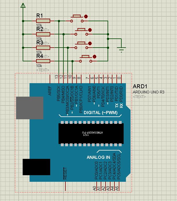

connect crystal , capacitors, resistors, buttons as show in the schematic...
if u r using arduino just connect push buttons and resistors............
we need to connect resistor In electronic logic circuits, a pull-up resistor is a resistor connected between a signal conductor and a positive power supply voltage to ensure that the signal will be a valid logic level if external devices are disconnected or high-impedance is introduced.
THE CODE
For PIC18f users..
i used HI-TECH COMPILER.
#include
void serialwrite(unsigned char data) \\ usart send byte code
{
TXREG=data;
while(TXIF==0);
}
void main() \\main function
{
TXSTA=0X20; \\transmit enable
RCSTA=0X90; \\serial ON
SPBRG=129; \\9600 baud rate
BRGH=1; \\high speed to reduce error
TRISC7=1; \\rx as input
TRISC6=0; \\tx as output
TRISD0=1; \\ button pins as input
TRISD1=1;
TRISD2=1;
TRISD3=1;
while(1)
{
if(RD0==0) { \\ if button 1 is pressed
while(RD0==0); \\debounce loop
serialwrite('1'); \\send 1
}
if(RD1==0) {
while(RD1==0);
serialwrite('2');
}
if(RD2==0) {
while(RD2==0);
serialwrite('3');
}
if(RD3==0) {
while(RD3==0);
serialwrite('4');
}
}
}
For ARDUINO users..
const int buttonpin1 = 13; \\ buttonpins
const int buttonpin2 = 12;
const int buttonpin3 = 11;
const int buttonpin4 = 10;
void setup()
{
pinMode(buttonpin1, INPUT); \\ making all button pins as input
pinMode(buttonpin2, INPUT);
pinMode(buttonpin3, INPUT);
pinMode(buttonpin4, INPUT);
Serial.begin(9600); \\ turn on serial at 9600 baud rate
}
void loop()
{
if (digitalRead(buttonpin1)==LOW) \\ check if button 1 is pressed
{
while(digitalRead(buttonpin1)==LOW); \\if so then wait until its is released
Serial.write("1"); \\send one through serial port
}
if (digitalRead(buttonpin2)==LOW)
{
while(digitalRead(buttonpin2)==LOW);
Serial.write("2");
}
if (digitalRead(buttonpin3)==LOW)
{
while(digitalRead(buttonpin3)==LOW);
Serial.write("3");
}
if (digitalRead(buttonpin4)==LOW)
{
while(digitalRead(buttonpin4)==LOW);
Serial.write("4");
}
delay(5);
}
A SIMPLE VB CODE

Public Class GamepadLauncher
Private Sub Button1_Click(ByVal sender As System.Object, ByVal e As System.EventArgs) Handles Button1.Click
If SerialPort1.IsOpen = False Then
If TextBox1.Text <> "" And TextBox2.Text <> "" Then
SerialPort1.PortName = TextBox1.Text
SerialPort1.BaudRate = TextBox2.Text
If SerialPort1.IsOpen = False Then
SerialPort1.Open()
MsgBox("Serial Opened")
Timer1.Enabled = True
End If
Else
MsgBox("Enter COM port and Baud Rate")
End If
End If
End Sub
Private Sub Form1_Load(ByVal sender As System.Object, ByVal e As System.EventArgs) Handles MyBase.Load
SerialPort1.Close()
End Sub
Private Sub Button2_Click(ByVal sender As System.Object, ByVal e As System.EventArgs) Handles Button2.Click
If SerialPort1.IsOpen = True Then
SerialPort1.Close()
Timer1.Enabled = False
End If
End Sub
Private Sub Timer1_Tick(ByVal sender As System.Object, ByVal e As System.EventArgs) Handles Timer1.Tick
Dim a As String = ""
a = SerialPort1.ReadExisting
TextBox3.Text = TextBox3.Text + a
If a = "1" Then
SendKeys.Send("{up}")
ElseIf a = "2" Then SendKeys.Send("{down}")
ElseIf a = "3" Then SendKeys.Send("{left}")
ElseIf a = "4" Then SendKeys.Send("{right}")
End If
End Sub
End Class
Download Subway Surfers for Pc or Laptop !!!!

download Subway Surfers for pc by clicking following key without bluestacks or Intelapp
http://kamroon.weebly.com/subway-surfers.html
and install both subway surfers and AutoHotkey software and run the "AutoHotkey script" every time when u open
subway surfers
Final Step
- PROGRAM PIC18F4520 using the pic code mentioned above and connect to serial port
if u r using ARDUINO then program it using above code
note down the COMPORT number from START--->CONTROL PANEL-->DEVICE MANAGER--> USB port ..
- RUN the VB Application and select com port in first textbox and write 9600 baud rate in second box and click open serial ..
- Press a button1 on MCU board the ASCII value of "1" will be displayed in bottom textbox of vb application
then its working
- Now run AutoHotkey Script and run SubwaySurfers......
you can download VB application from the following link.........
ENJOY!!!!