Gamecube Controller USB Adapter (and Getting Started With the STM32F1)
10094 Views, 23 Favorites, 0 Comments
Gamecube Controller USB Adapter (and Getting Started With the STM32F1)


We have Dance Dance Revolution pads with Gamecube plugs for the Wii, and I wanted to be able to play games on the PC using a dance pad--I thought (rightly!) that Tetris would be particularly fun. As a bonus, I also wanted to be able to use our (knock-off) Gamecube controller to for games on the PC, as I don't have any PC gamepad.
One can buy a GameCube Controller adapter for $16, but I am cheap, and I wanted to be able to have different settings for different games, without any software fiddling on the PC side (GlovePIE, FreePIE, vJoystick, etc.) For instance, for some games I want the pad (and the sticks on the Gamecube controller) to generate arrow keys; forfor other games, I want it to generate WASD controls; for some I want to use the Gamecube controller as a joystick with different button mappings for different games.
The solution is a $2-4 "blue pill" or "black pill" STM32F1 development board (the black pills are now hard to find [2023]). It's more powerful than an Arduino (32-bit ARM processor at 72MHz), has a USB peripheral, runs at the 3.3v needed for the Gamecube controller, and already has software (after a patch or two) that supports USB Keyboard/Joystick/Mouse all at once.
This Instructable will also tell you how to get started making USB HID devices with the STM32F1 and the Arduino IDE.
The design allows for up to 15 different operation modes, indicated by four LEDs. One can switch operation modes with two push buttons. For instance, mode 1 is a joystick emulation that merges the two shoulder buttons into a single sliders, mode 2 is a joystick emulation that keeps the shoulder buttons as separate sliders and mode 4 emulates keyboard arrow keys.
Parts needed:
- "Blue pill" or "black pill" STM32F103C8T6 minimum development system. Don't get the slightly cheaper red or blue ones, as they have deficiencies. Aliexpress has clones, but clones should work fine for this project.
- Gamecube extension cable.
- Four red LEDs
- Four 220ohm resistors
- Two momentary switches (one will do in a pinch)
- One 10 uF capacitor
- One 100 nF capacitor
- A small piece of protoboard (I cut it from a larger chunk)
- Wire
- Solder
- Something to put it in (a small cardboard box; a food container; I made a 3D printed case)
Tools needed:
- Computer
- Arduino or other UART-to-USB bridge device
- Soldering iron
- Micro USB cable
- Multimeter or continuity tester
- Optional: 3D printer
- Optional: 2D printer
Here's the github page for the software.
Install Bootloader on Development Board
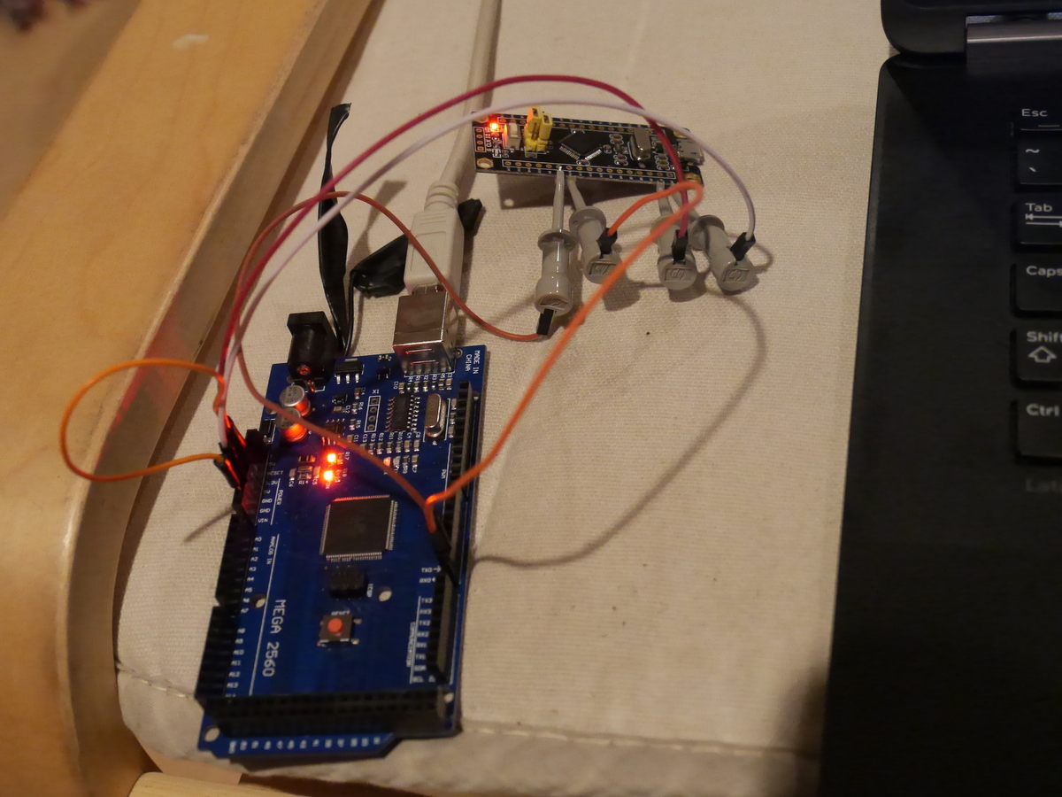
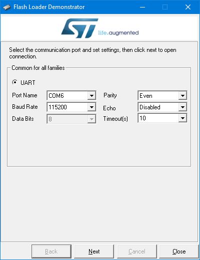
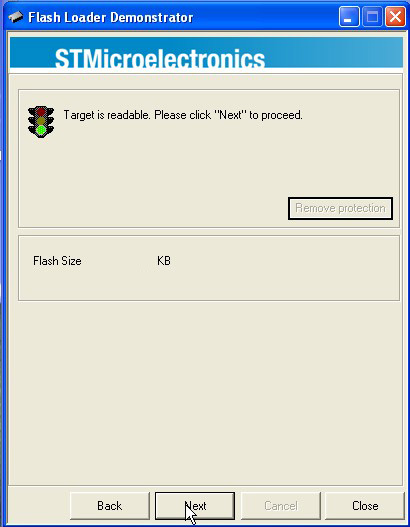
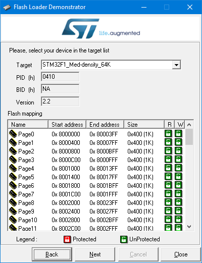
Solder the two three-pin headers in the middle of the Black Pill development system (B0-/center/B0+; B1-/center/B1+).
You need a UART to USB bridge that is compatible with 3.3v devices. You can order a ch340 from Aliexpress for $0.66, but I had an Arduino Mega knockoff sitting around, and there was a cool trick I found online. If on an Arduino you short the reset pin to ground with a short wire, then it becomes a UART to USB bridge--no sketch needed. The only trick is that the RX and TX labeling becomes reversed: the Arduino's "RX" pin transmits and its "TX" pin receives. The Arduino runs at 5v and the Black Pill at 3.3v, but the PA9 and PA10 pins on the stm32f103 are 5V tolerant according, so that shouldn't be a problem.
On the headers you soldered, put a jumper from B0+ to center and from B1- to center.
Make the following connections:
- PA9 to UART bridge RX ("TX" if you're using the Arduino trick)
- PA10 to UART bridge TX ("RX" if you're using the Arduino trick)
- G to UART bridge ground
I used logic probe tips to make the connections on the STM32 side, but you could also just solder in some wires that you can later cut off (or de-solder if you want to be neat)
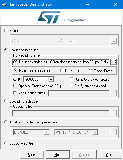
Download the bootloader binary. For blue pill you want generic_boot20_pc13.bin while for black pill you want generic_boot20_pb12.bin. On Windows, install ST's Flash Loader Demonstrator. On Linux (and maybe OS X and even Windows if you prefer commandline tools), use this python script instead, but my instructions will be for Windows.
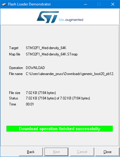
Connect your UART bridge to your computer. Power up the Pill via its USB port (best if you connect it to a charger rather than the computer, as the computer will likely complain about an unrecognized USB device). Start the Flash Loader Demonstrator. Choose the COM port for your UART bridge. Choose "Remove protection" if available. Choose a 64kb rather than 128kb flash version. And upload the bootloader binary.
Unpower everything and then move the jumper from B0+/center to B0-/center. You now have a bootloader that you can use with the Arduino IDE.
Set Up Arduino IDE

I assume you have the latest Arduino IDE installed.
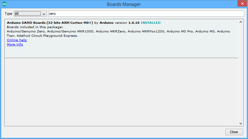
In Tools | Boards | Boards Manager, install support for the Arduino Zero (just put Zero in the search, click on the found entry, and then Install). Yes, you aren't working with a Zero, but this will install the right gcc compiler.
Next, download the stm32duino core (click on "Clone or download" and then "zip"). Put the branch in Arduino/Hardware/Arduino_STM32 (so you'll have folders like Arduino/Hardware/Arduino_STM32/STM32F1, etc.)
On Windows, install drivers by running drivers\win\install_drivers.bat.
Install my GameControllersSTM32 library: Go to Sketch | Include Library | Manage Libraries, and search for GameControllers. Click on it and click on Install.
Quick Test

Check to make sure everything is working. Start a new sketch (File | New...) and type in:
#include <USBComposite.h>
#include <libmaple/usb.h>

USBHID HID;
HIDKeyboard Keyboard(HID);
HIDJoystick Joystick(HID);
HIDMouse Mouse(HID);

void setup() {
  USBHID.begin(HID_KEYBOARD_MOUSE_JOYSTICK);
  while (!usb_is_connected(USBLIB) || !usb_is_configured(USBLIB)) delay(100);
  Keyboard.println("Hello world!");
}

void loop() {
  Joystick.X(0);
  Joystick.Y(0);
  digitalWrite(PB12, 0);
  delay(500);
  Joystick.X(1023);
  Joystick.Y(1023);
  delay(500);
  digitalWrite(PB12, 1);
}
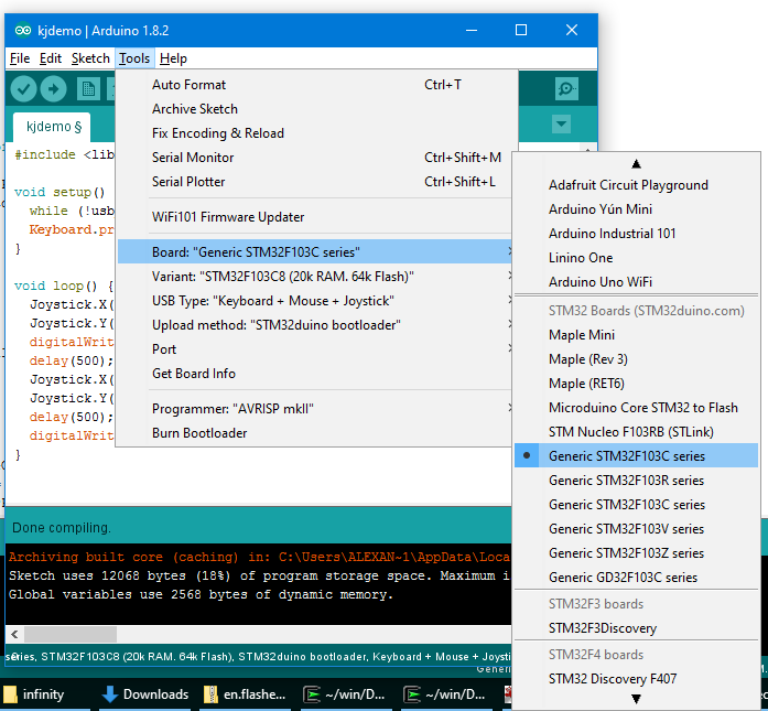
Go to Tools | Board and scroll down to select Generic STM32F103C series.
Finally, press the upload button (right arrow icon). As soon as it says "Searching for DFU device", plug the Black Pill in via the USB. Or if it's already plugged in, press the RESET on it, or unplug and plug it.
Unplug the device and plug it in while you have a working cursor in a text editor (e.g., in your Arduino sketch). It should type "Hello World!" in and be flashing the LED. Then double check to make sure that the joystick is moving between two opposite corners. On Windows, you can press Win-R, type joy.cpl, choose the Maple joystick device, press Properties, and you should see it move the joystick in time to the LED flashes.
If you have trouble uploading on Windows, check the permissions for all the files in your Arduino\Hardware\Arduino_STM32\tools\win folder. You can fix those permissions by right clicking on each in Windows explorer (but I just used cygwin and chmod 755 * will do the job.)
Congratulations! You now have a working system for Keyboard / Joystick / Mouse emulation and USB use. The device you have doesn't need any special drivers, and should work on all modern devices, including tablets that supply sufficient power to USB OTG.
Some programming hints if you want to make your own stuff:
1. To see what things you can do with Keyboard / Joystick / Mouse, have a look at this header file.
2. When using the Joystick and making several settings at once (e.g., emulating pressing multiple buttons), you should call Joystick.setManualReportMode(true) in your setup() function and then once you make all the settings (e.g., calling Joystick.X(), Joystick.Y(), Joystick.button()), call Joystick.sendManualReport(). Otherwise, you will be sending a USB HID report separately with each setting, which will increase latency.
3. It's also a good idea to check if usb_is_connected(USBLIB) && usb_is_configured(USBLIB) before calling any USB reporting function, as otherwise your device may hang. In the sample sketch, I wait for an established connection in the setup() code (which is imperfect, because if your laptop hibernates, it may switch the port from a USB connection to a pure charging port, and then the code will hang). In my own code, I also set a watchdog timer to reboot the device if there is a hang.
4. Here is documentation on some of what's available.
Install Sketch
Just as you did with the demo sketch, install my Gamecube USB adapter sketch on the device (you can download the zip file and extract it to an Arduino/gamecubecontroller directory).
Print out the list of emulation modes.
Electronics


I used a small bit of protoboard to mount the four mode LEDs and two mode-switch buttons (up and down), as well as the one pull-up resistor for Gamecube data. I brought out 3.3V to the protoboard, but I didn't need to bring out ground to it, though you can if you like.
Cut the Gamecube extension cable. We will be working with the socket side, the one that the Gamecube controller will plug in. See the photo of the socket for connection numbers. Note the flat side on the top of the photo. Check which connection numbers correspond to which pins (use a multimeter, continuity tester, etc.)
Make the following connections:
- 10uF and 100nF capacitors between 3.3v and ground (with the minus side of any electrolytics at ground). These should be as close to the chip as possible, so I soldered them right on the development board rather than the protoboard.
- Gamecube socket #2 -- PA6 on stm32 board
- Gamecube socket #2 -- one end of 1Kohm resistor on protoboard
- Other end of 1Kohm resistor -- 3.3V on stm32 board (or on protoboard)
- Gamecube socket #3 and #4 -- ground on stm32 board
- Gamecube socket #6 -- 3.3V on stm32 board (or on protoboard)
- LED in series with 220ohm (or bigger) resistor between PA0 on stm32 board and 3.3V (negative end (flat) to PA0; positive end to 3.3V)
- Repeat with LED+resistor between PA1 and 3.3V, PA2 and 3.3V, and PA3 and 3.3V
- Connected momentary switch between PA5 on stm32 board and 3.3V; this switch increments the mode number
- Optional: Connect momentary switch between PA4 on stm32 board and 3.3V; this switch decrements the mode number.
Before soldering you might want to do some quick temporary connections to test out the device with your computer. The crucial ones are the ones involving the Gamecube sockets. You can leave the LEDs and the buttons off initially.
Make a Case and Use


I made a customizable OpenSCAD file for the case if you have a 3D printer. You may need to modify some of the dimensions if you laid your components out differently. Print and screw in components. One side has holes for LEDs and momentary buttons (make sure that yours fit), and the other has no holes and is for the black pill.
Or you can use some plastic or cardboard box with holes cut in it.
For strain relief on the Gamecube cable, I knotted it inside the case and then put some Shoe Goo on the outer portion near the case.
To use, just switch between modes--indicated using binary numbers--using the momentary button (or buttons).
Set mode 0010 (first two LEDs off, next one on, and last one off) and calibrate using your operating system's joystick calibration utility (e.g., joy.cpl on Windows). Be careful when calibrating the Gamecube controller shoulder buttons in Windows to press them very slowly until they click. Otherwise, the last bit of the range before the click will be omitted.
To play Tetris on tetris.com, for instance, use the 0110 mode which makes both the controller sticks and the dance pad directions generate keyboard arrow keys, and make the A button generate a spacebar.
Adding More Modes
Chances are you will have games that don't work perfectly with any of the eight modes I made, or else you'll want to customize the modes. The modes I included are briefly described on the mode list you printed out, and a more detailed definition is in gamecube.h.
If you just want to remap the controller / dance pad buttons, create a new InjectedButton_t variable in gamecube.h, and then add that variable, together with one of the stick mapping functions (either joystickUnifiedShoulder, joystickDualShoulder or NULL), to the injectors list in that file. Have a look at the existing entries to figure out the format. Then upload the new sketch.
More fancy modes may require a new stick mapping function or some other custom code. That needs to be done in remap.ino.