GRBL Based DIY Drawing Machine
by shubhamsuresh in Circuits > Arduino
8362 Views, 14 Favorites, 0 Comments
GRBL Based DIY Drawing Machine
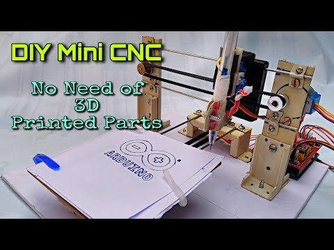
Hello all, I hope you are doing good and safe. I'm here with another very cool project which you can build using some scrap/ used parts. In this Instructables I'm going to show you how you can make a GRBL based mini CNC plotter Machine at home without using any 3D printed parts. by using this CNC plotter machine you can draw logo and can write text also. For better understanding, you can refer to this video.
What You Need to Make This Project?
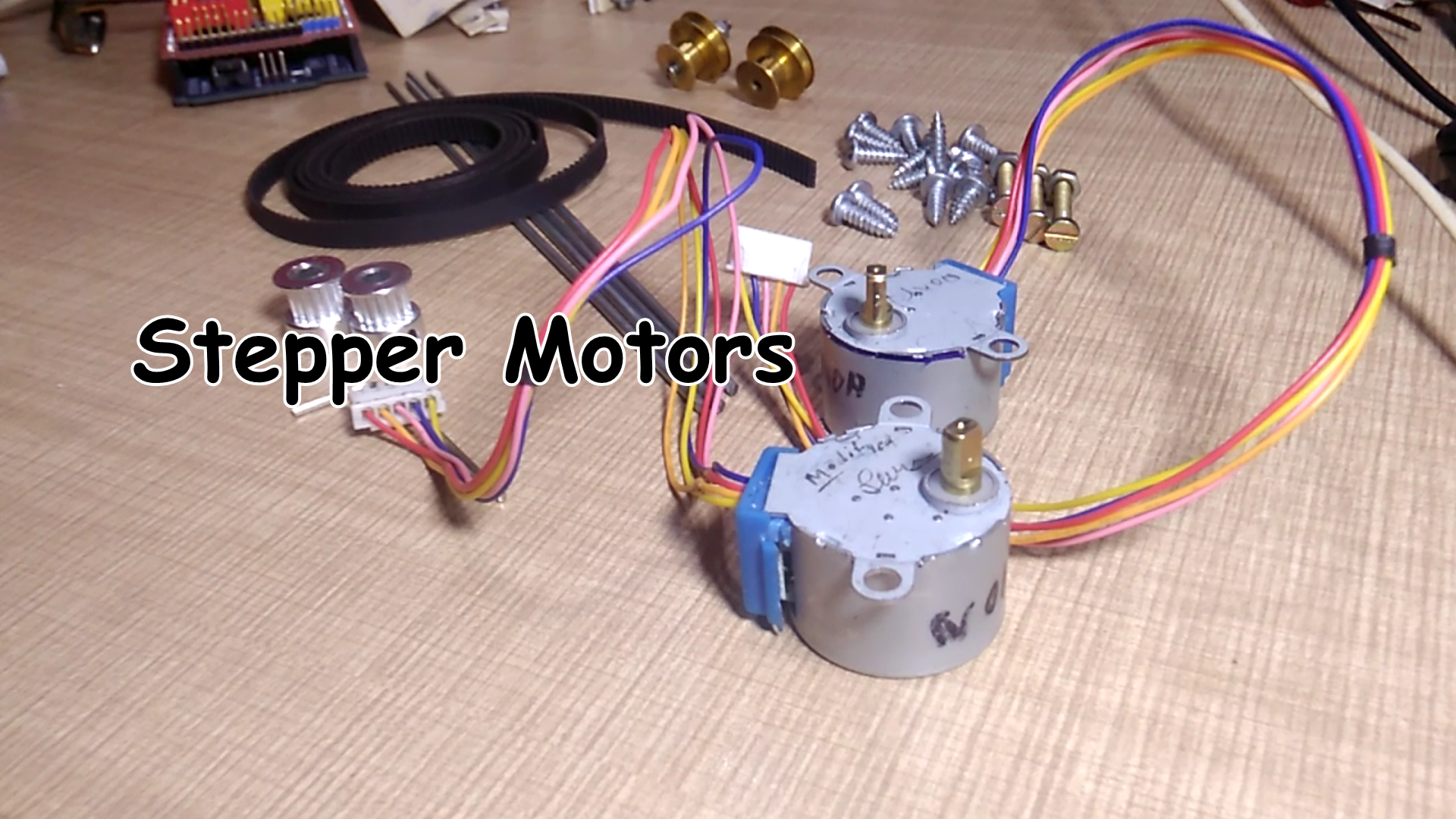
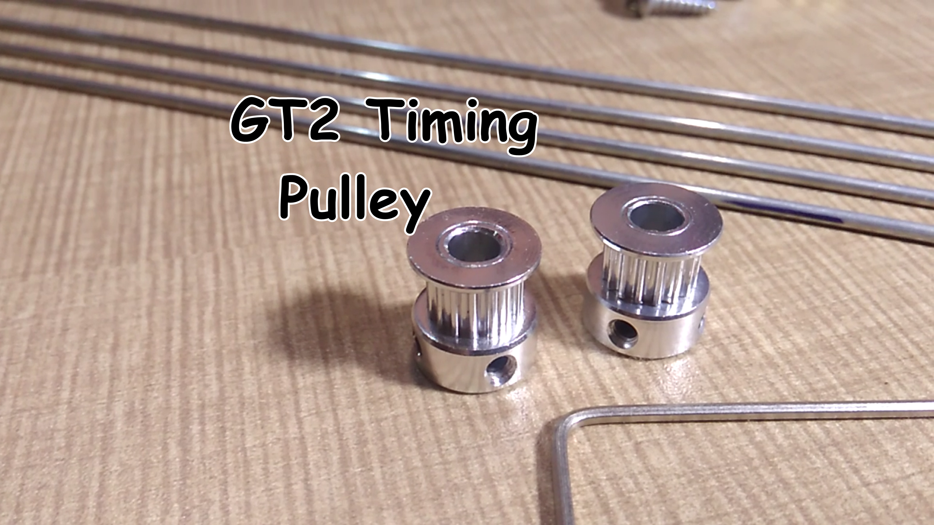
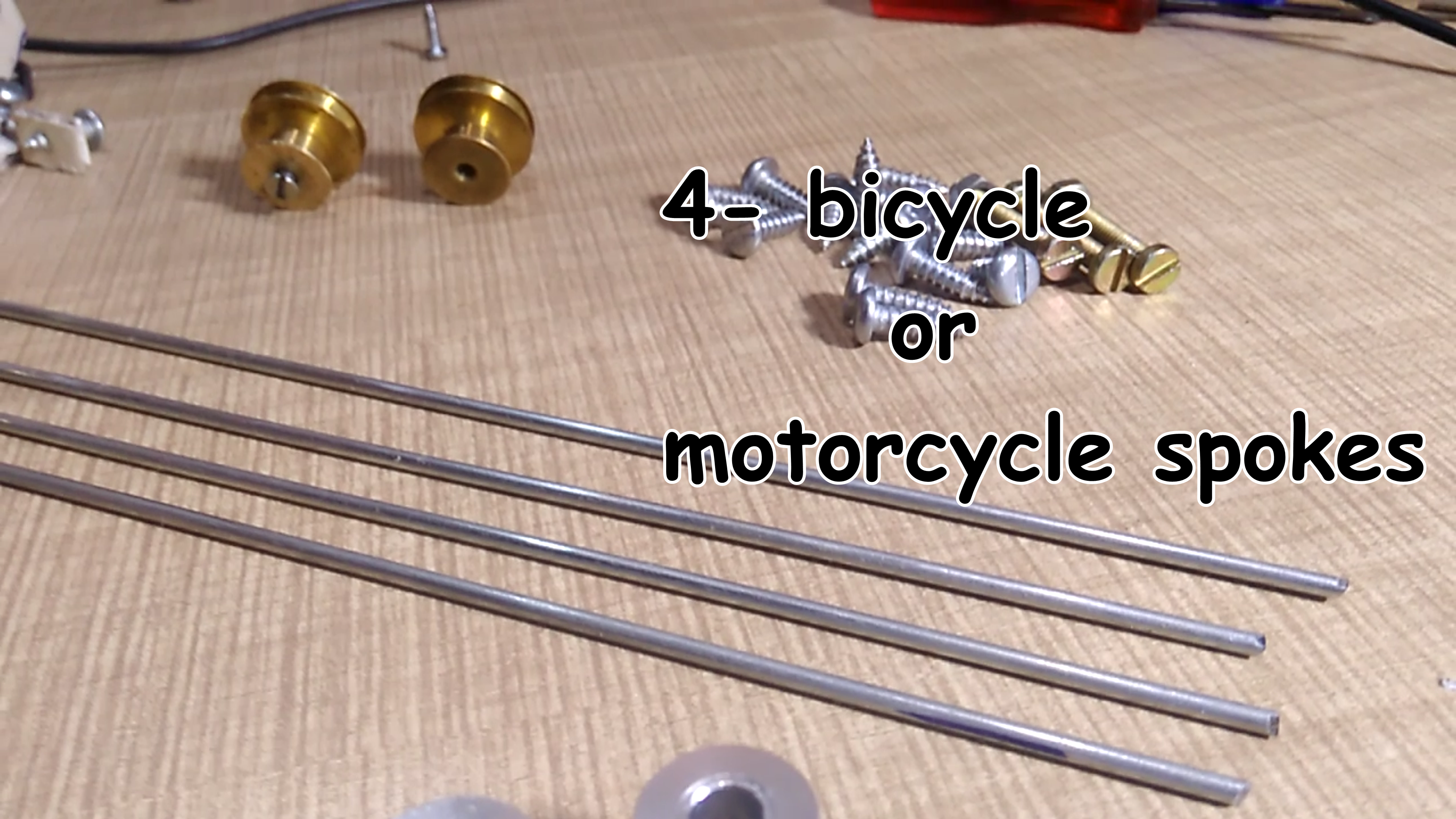
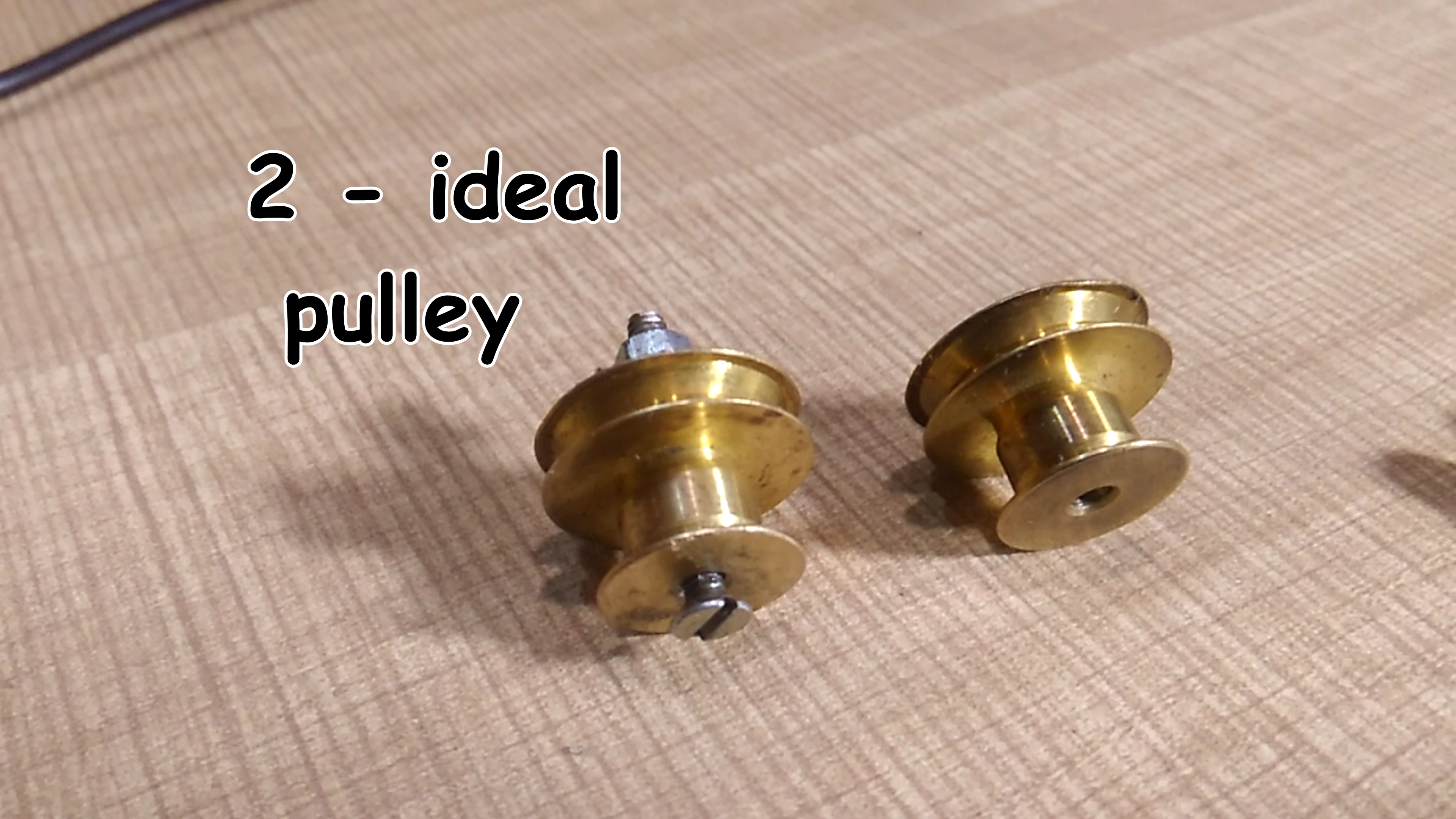
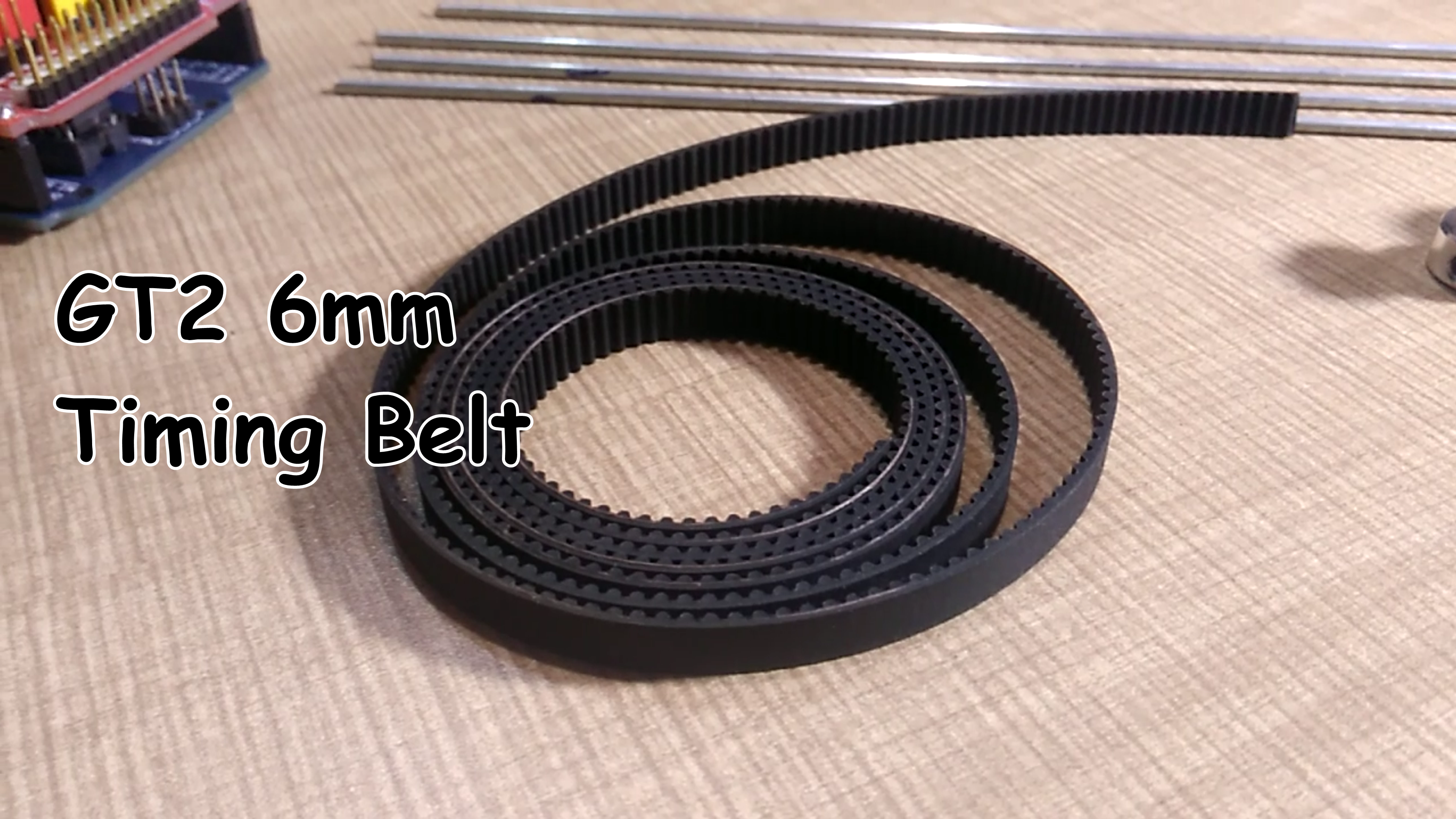
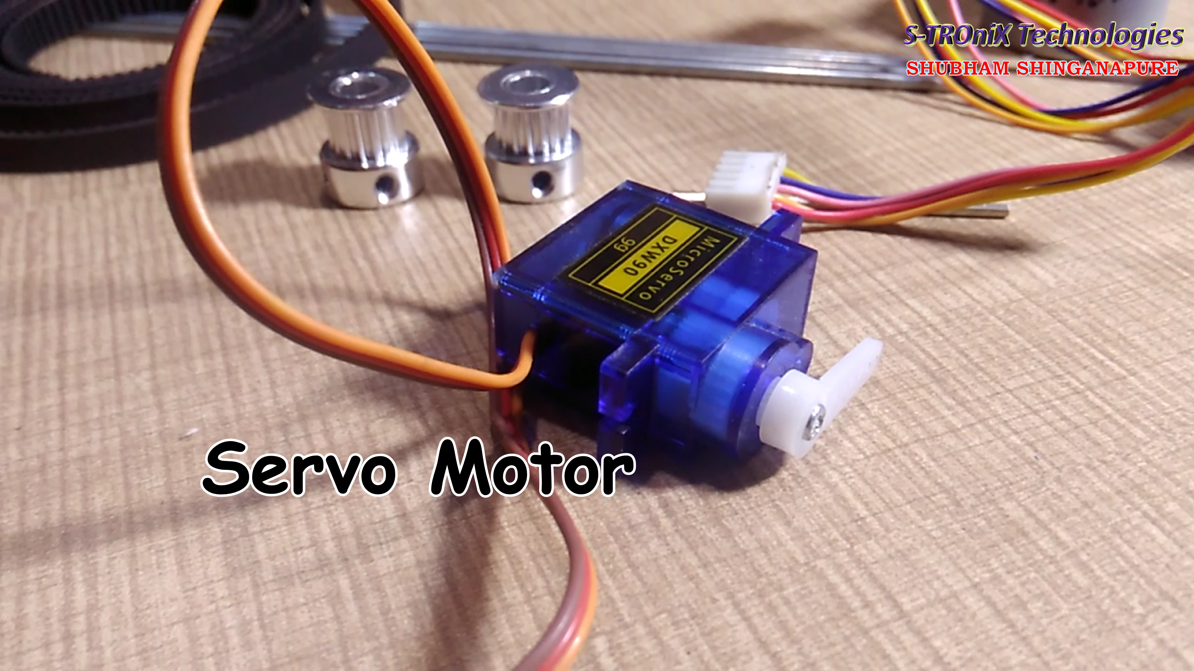
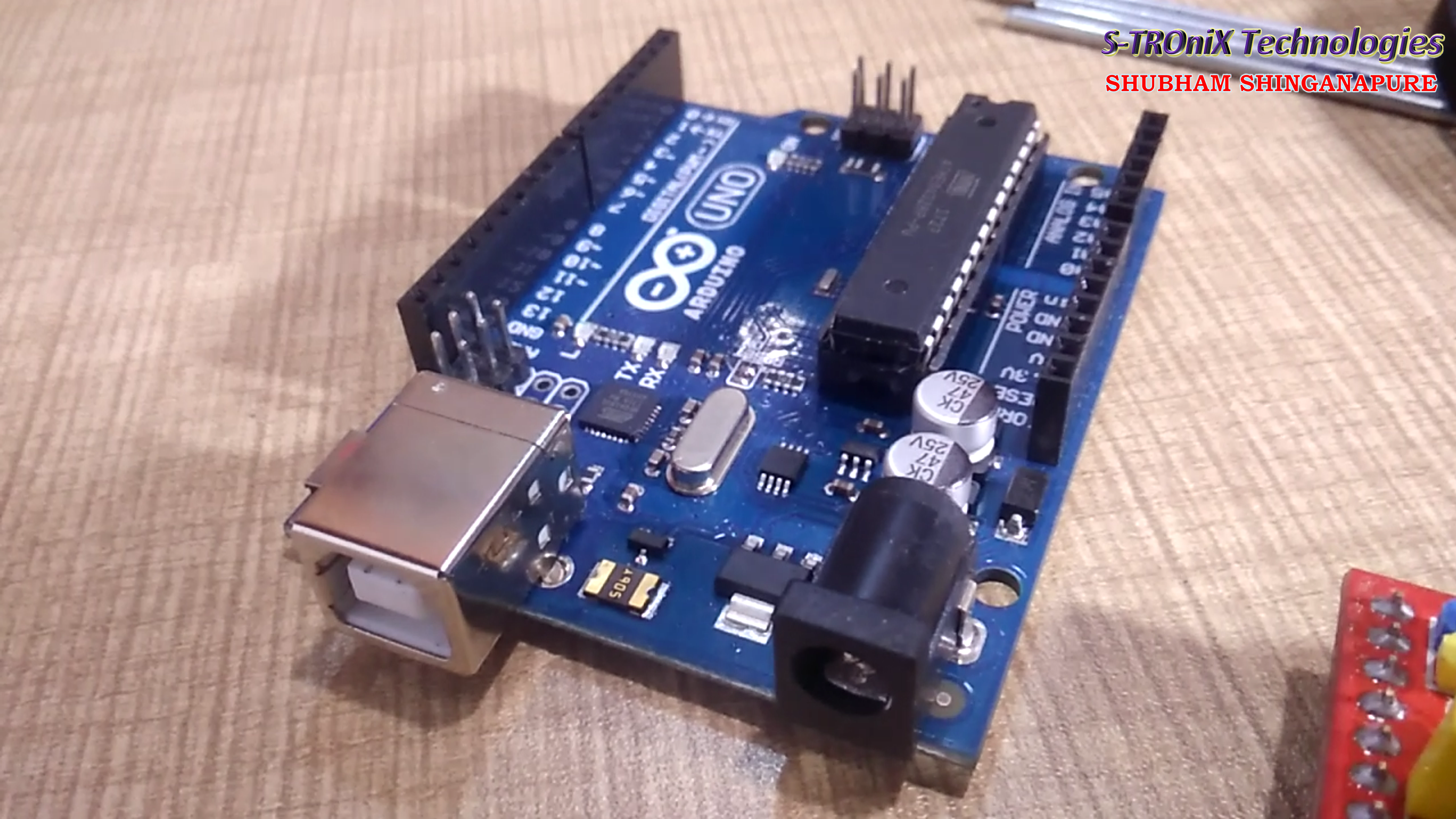
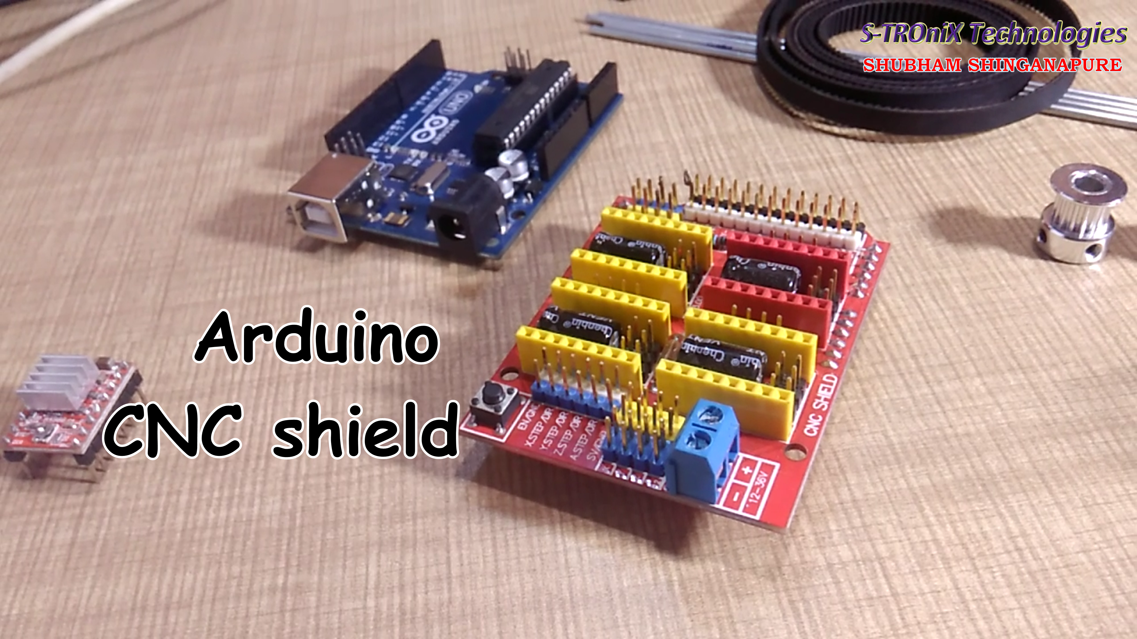
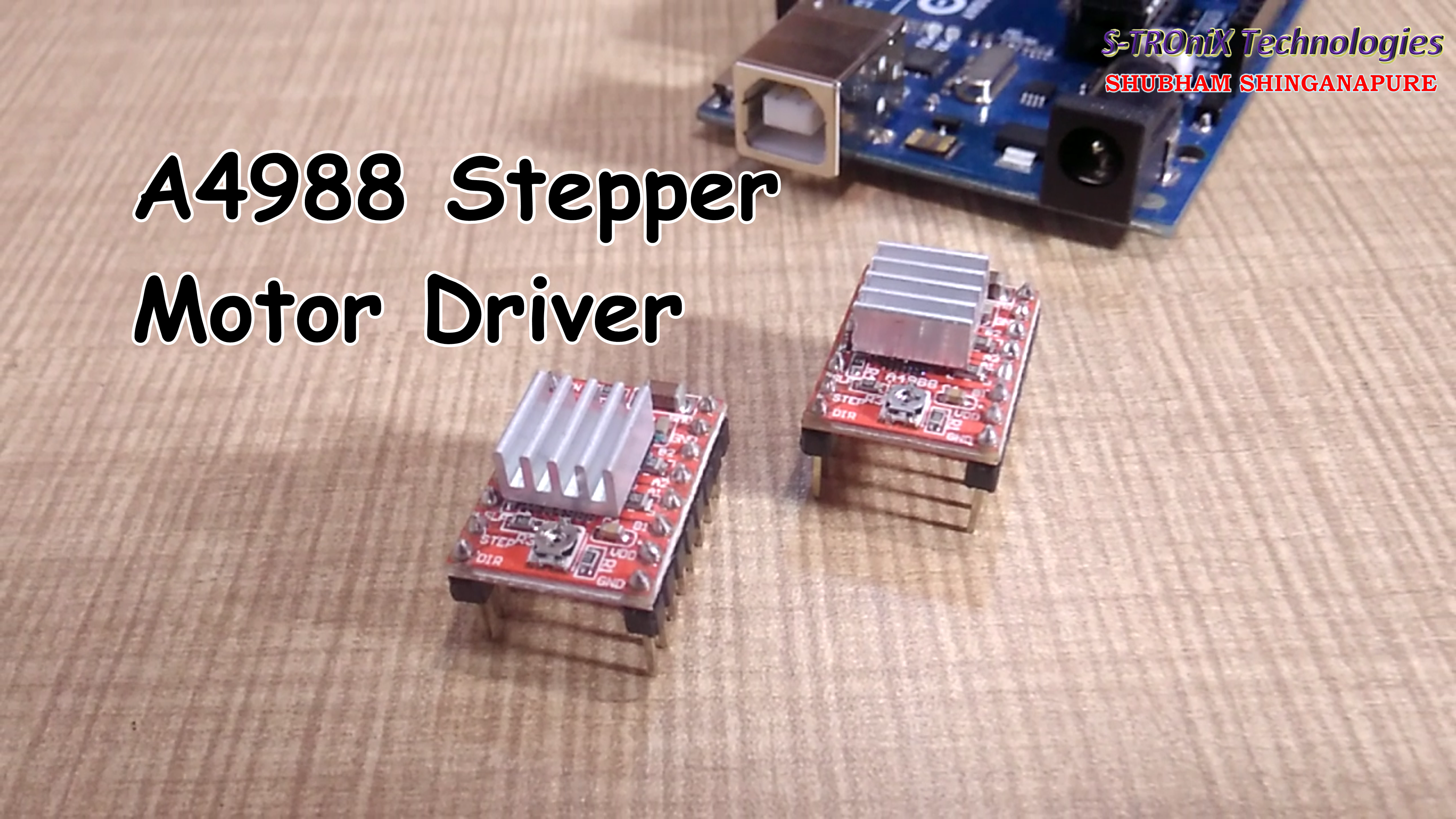
To make this project you need all the following components. Buy link for some components is given below and some components you have to collect from the local hardware shop.
Components Used
1- Arduino UNO x1 -----------------------------------------------INDIA / USA
2- CNC shield x1 -----------------------------------------------INDIA / USA
3- A4988 Motor driver x2 ---------------------------------------INDIA / USA
4- Stepper Motor x2 ---------------------------------------------INDIA / USA
5- GT2 Pulley x2 --------------------------------------------------INDIA / USA
6- GT2 Timing belt ----------------------------------------------- INDIA / USA
7- Servo Motor x1-------------------------------------------------INDIA / USA
8- Ideal Pulley x2--------------------------------------------------INDIA / USA
9- 12V2A Adaptor x1 --------------------------------------------INDIA / USA
10- Motorcycle Spocks/ 3mm Thick Round bars ----------- from the local store.
11- PVC casing ---------------------------------------------------- from the local store.
12- Pice of cardboard / MDF ----------------------------------- from the local store.
Let's Start.
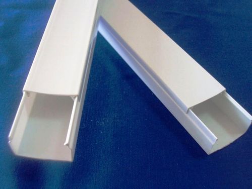
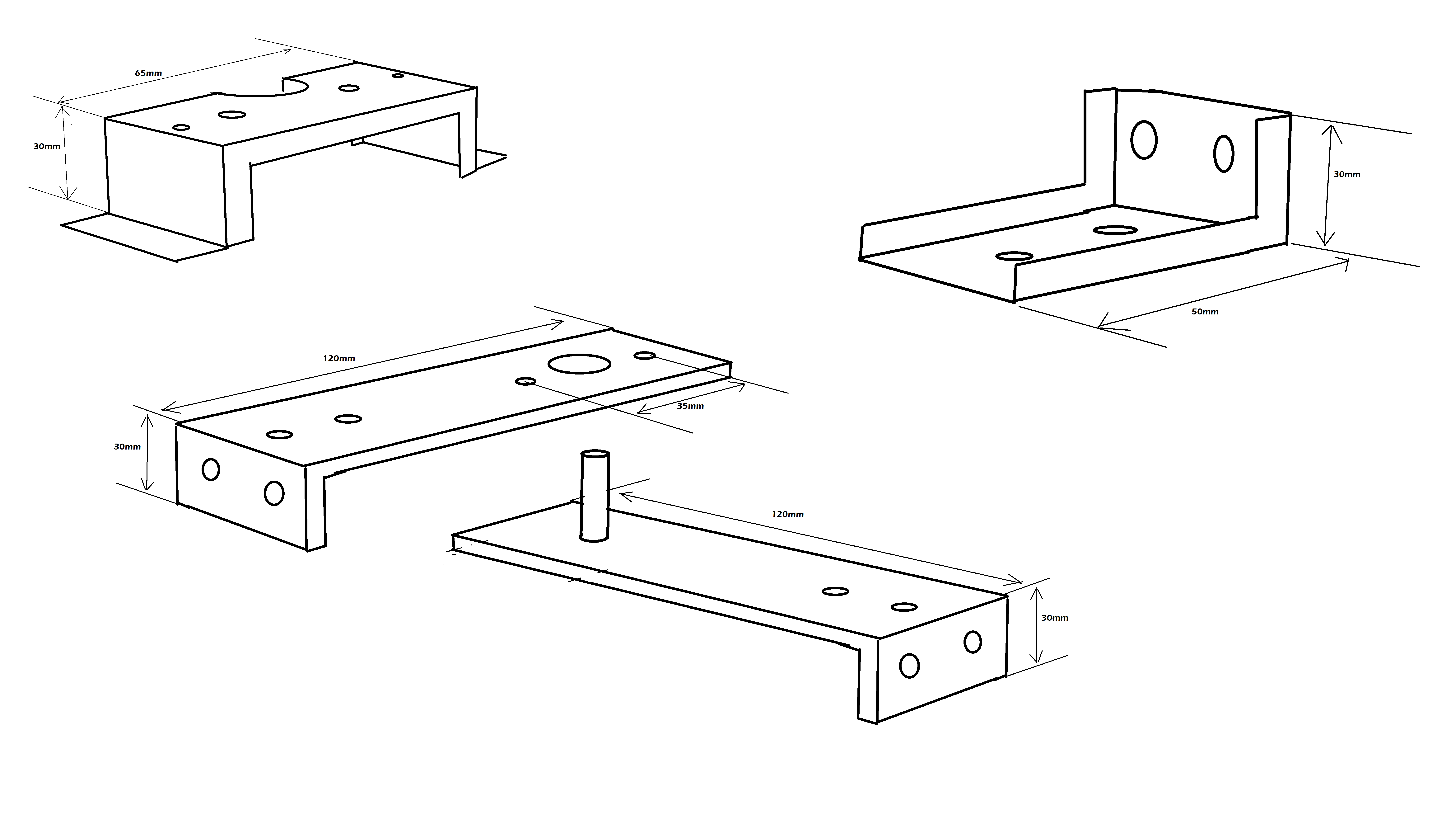
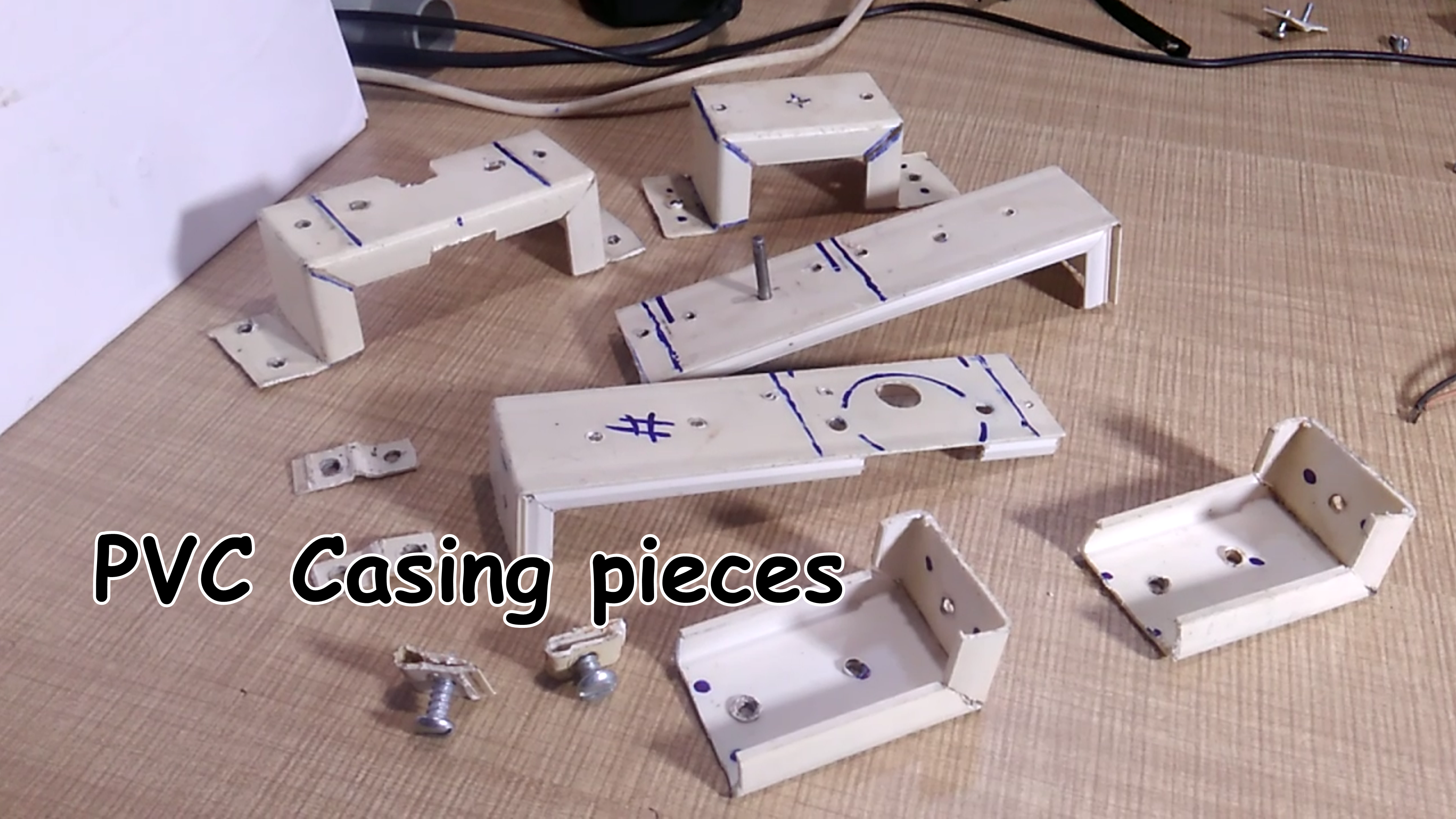
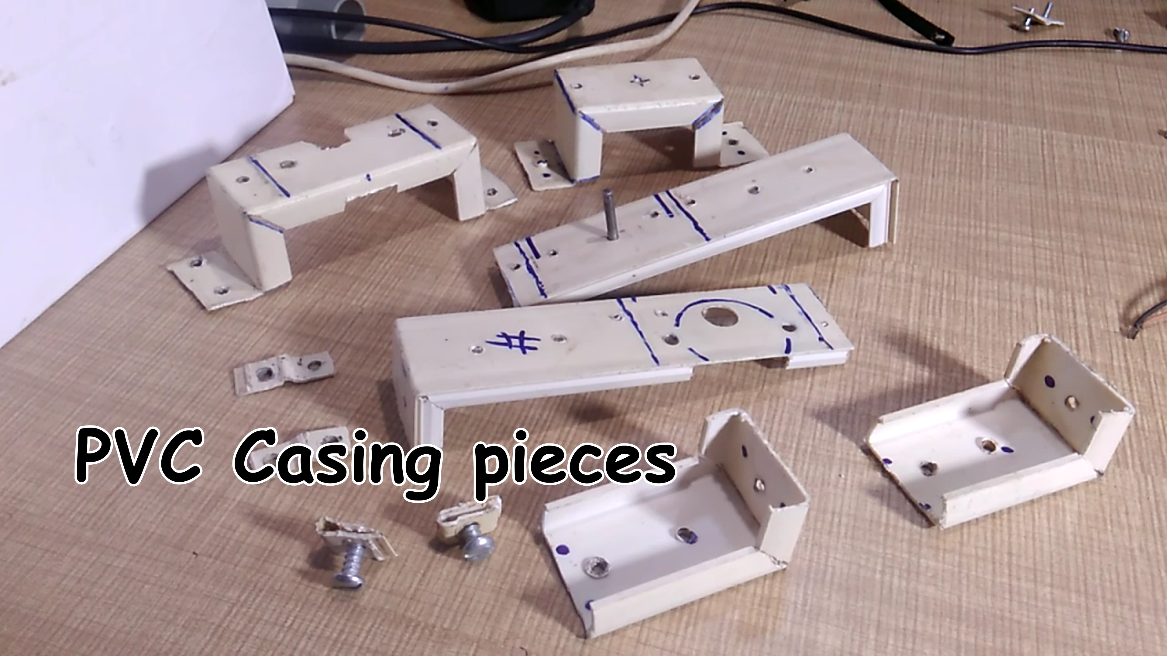
I made all parts for this machine using the PVC casing (see picture). Take a PVC casing and cut and bent it as per the given dimensions. apply some heat to the casing while banding it. make the holes for fixing the motors and rods.
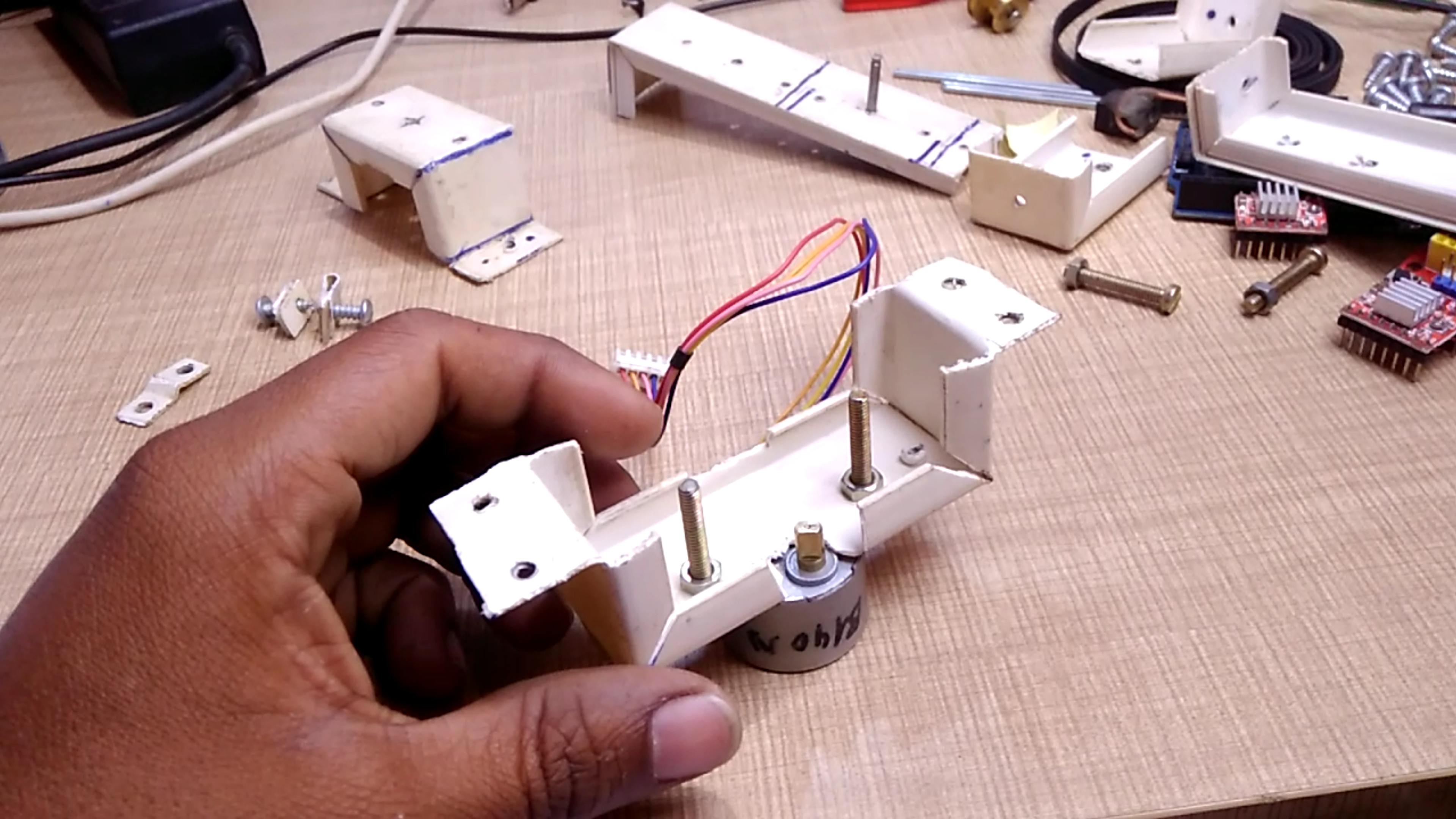
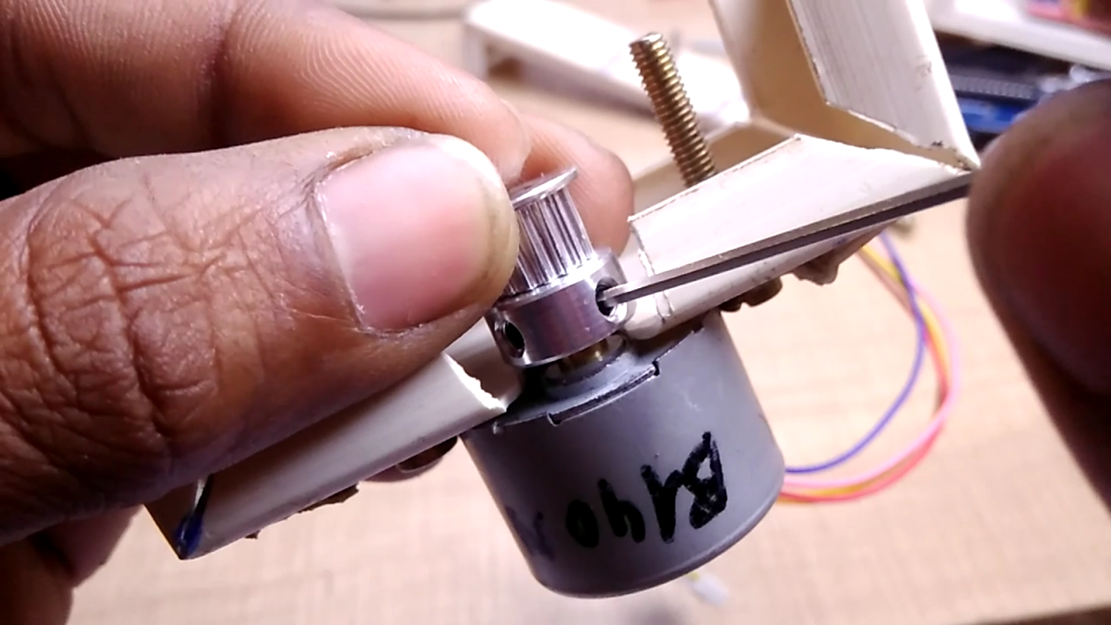
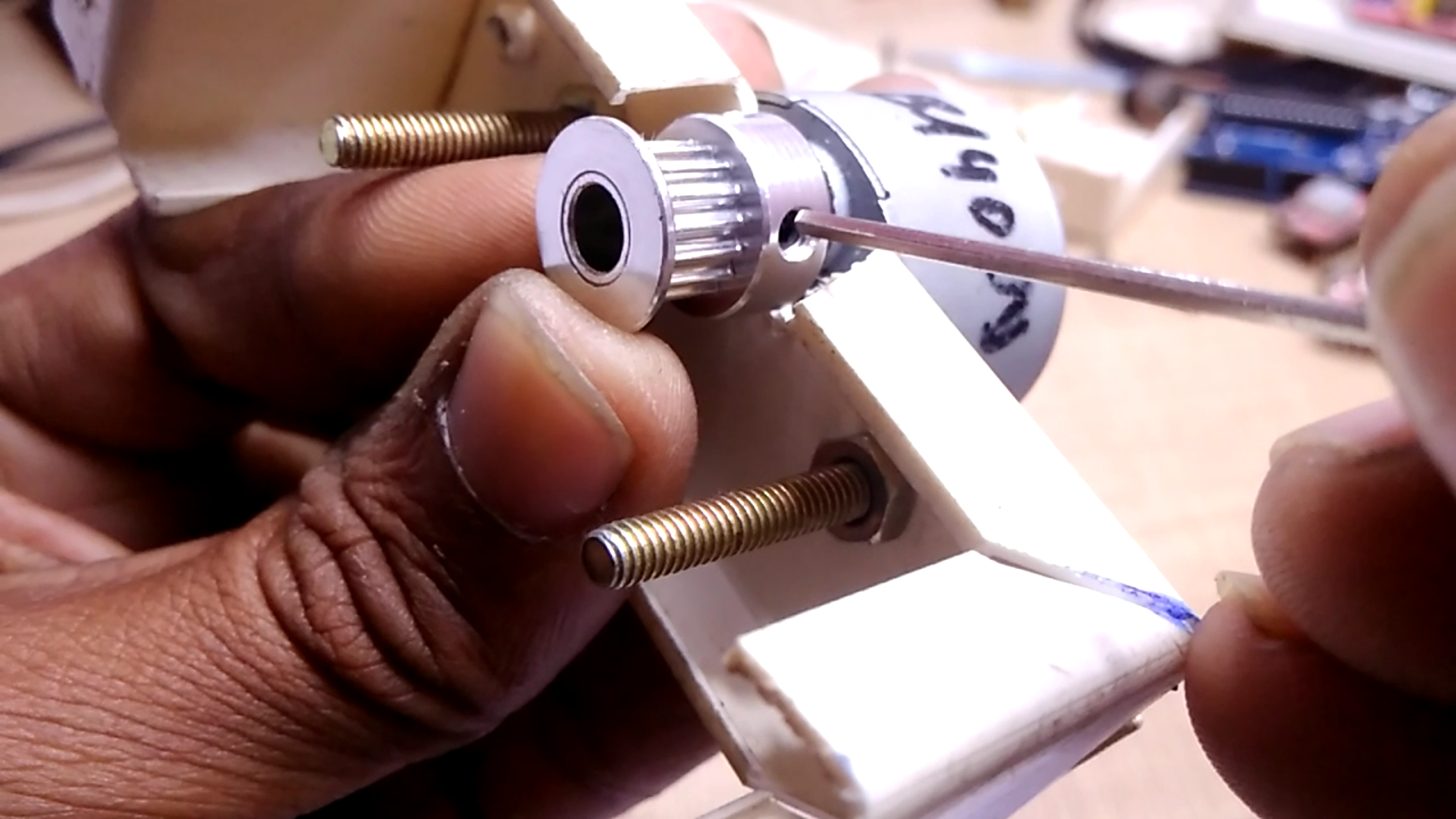
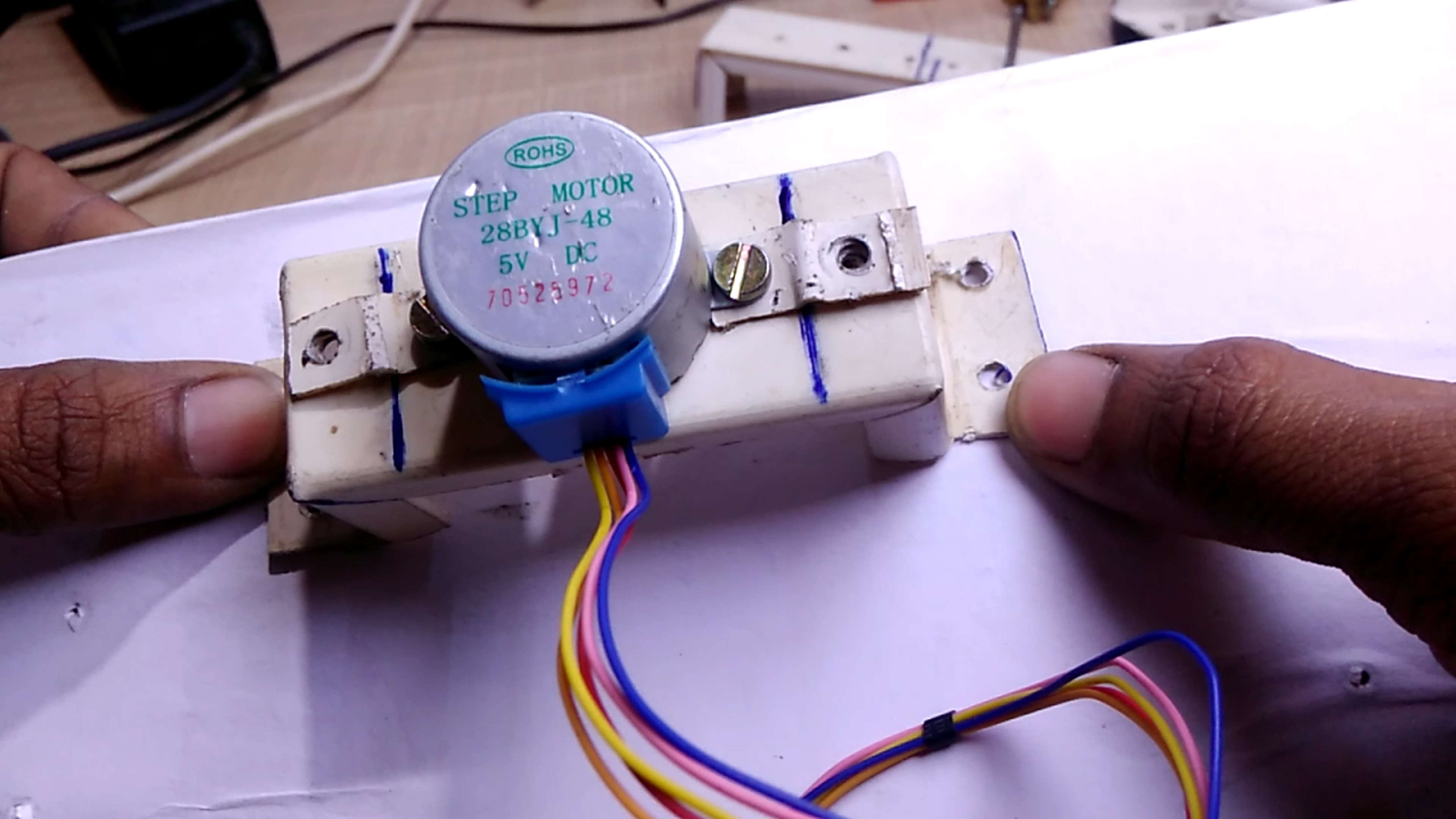
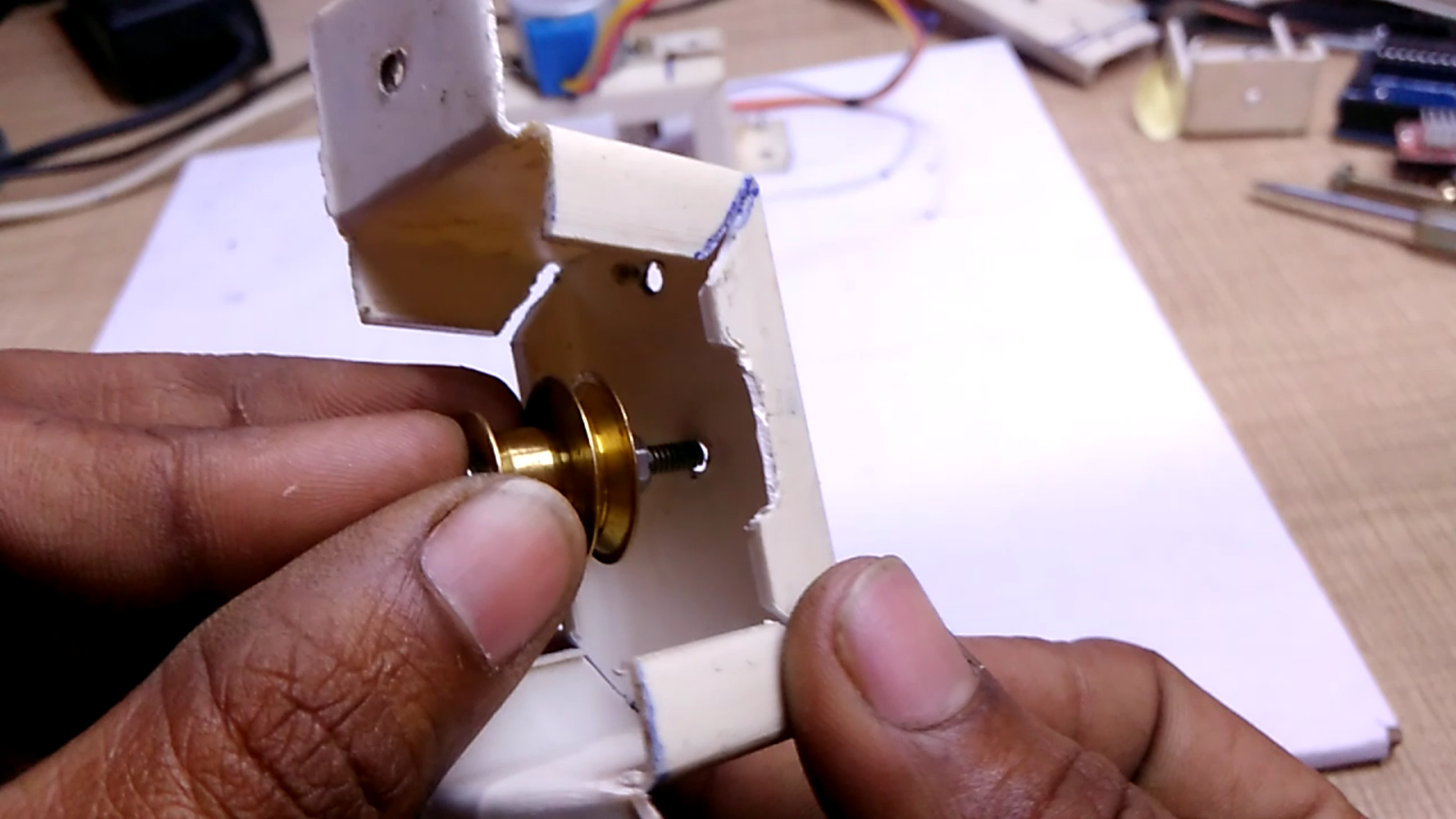
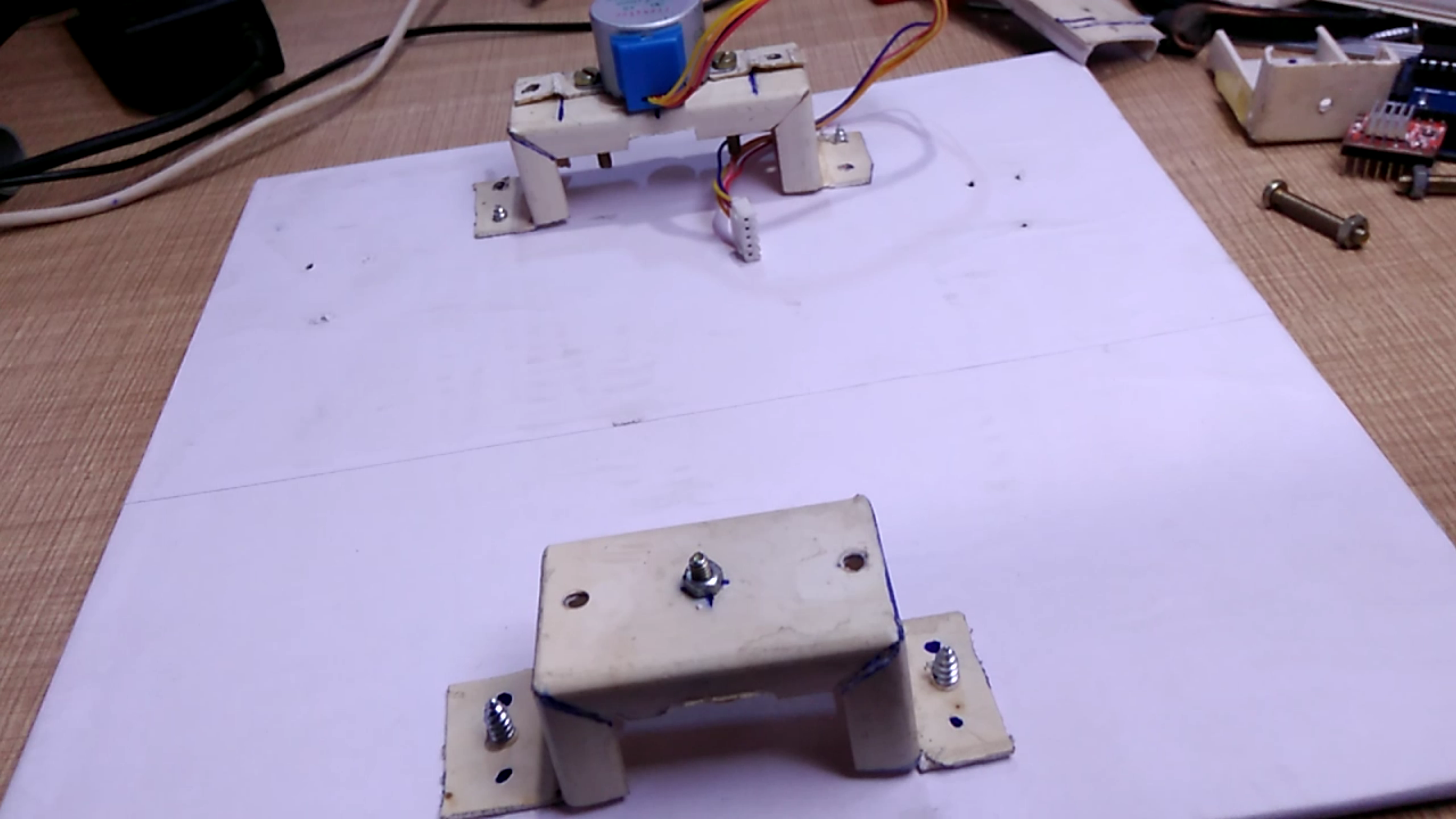
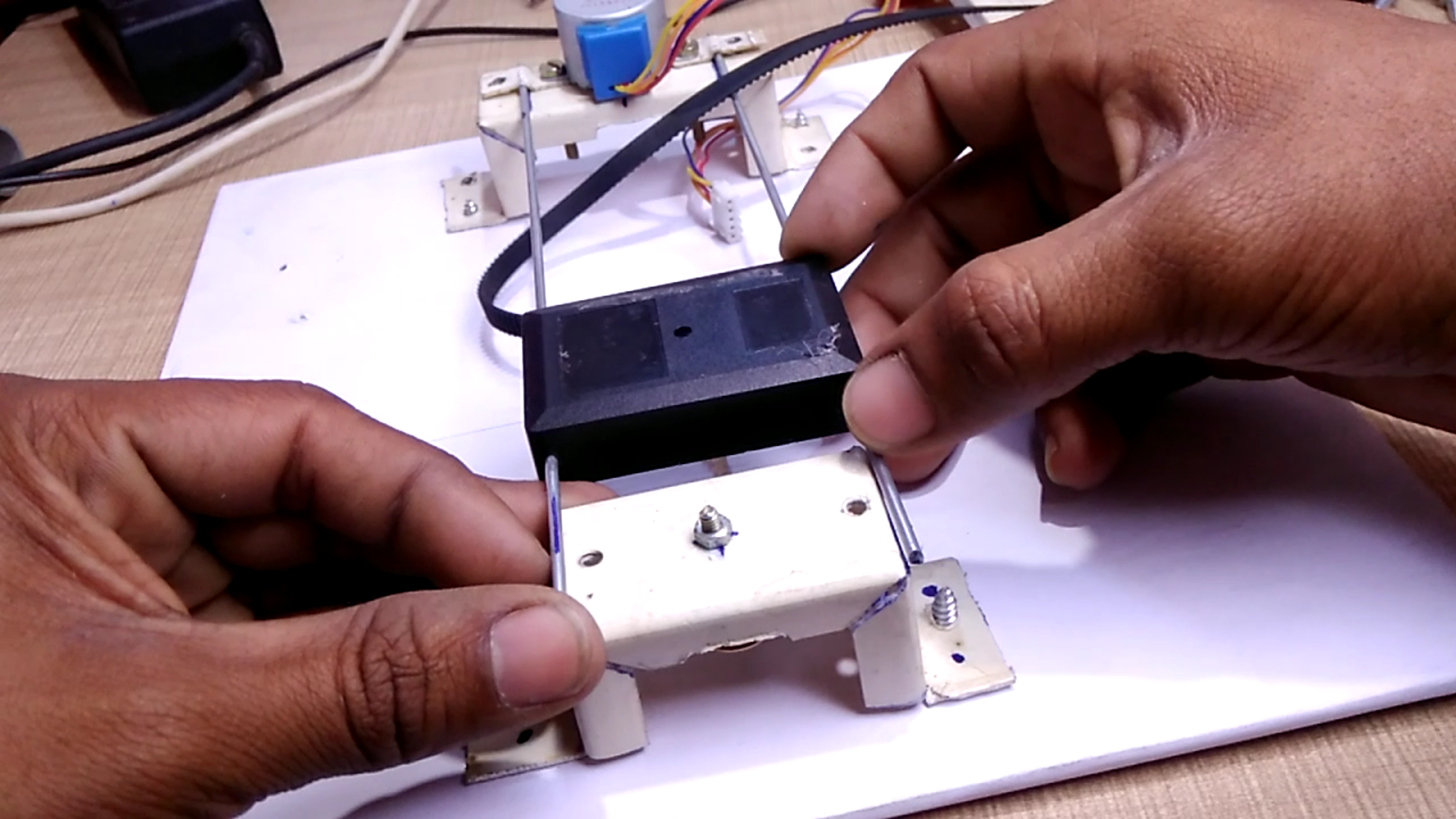
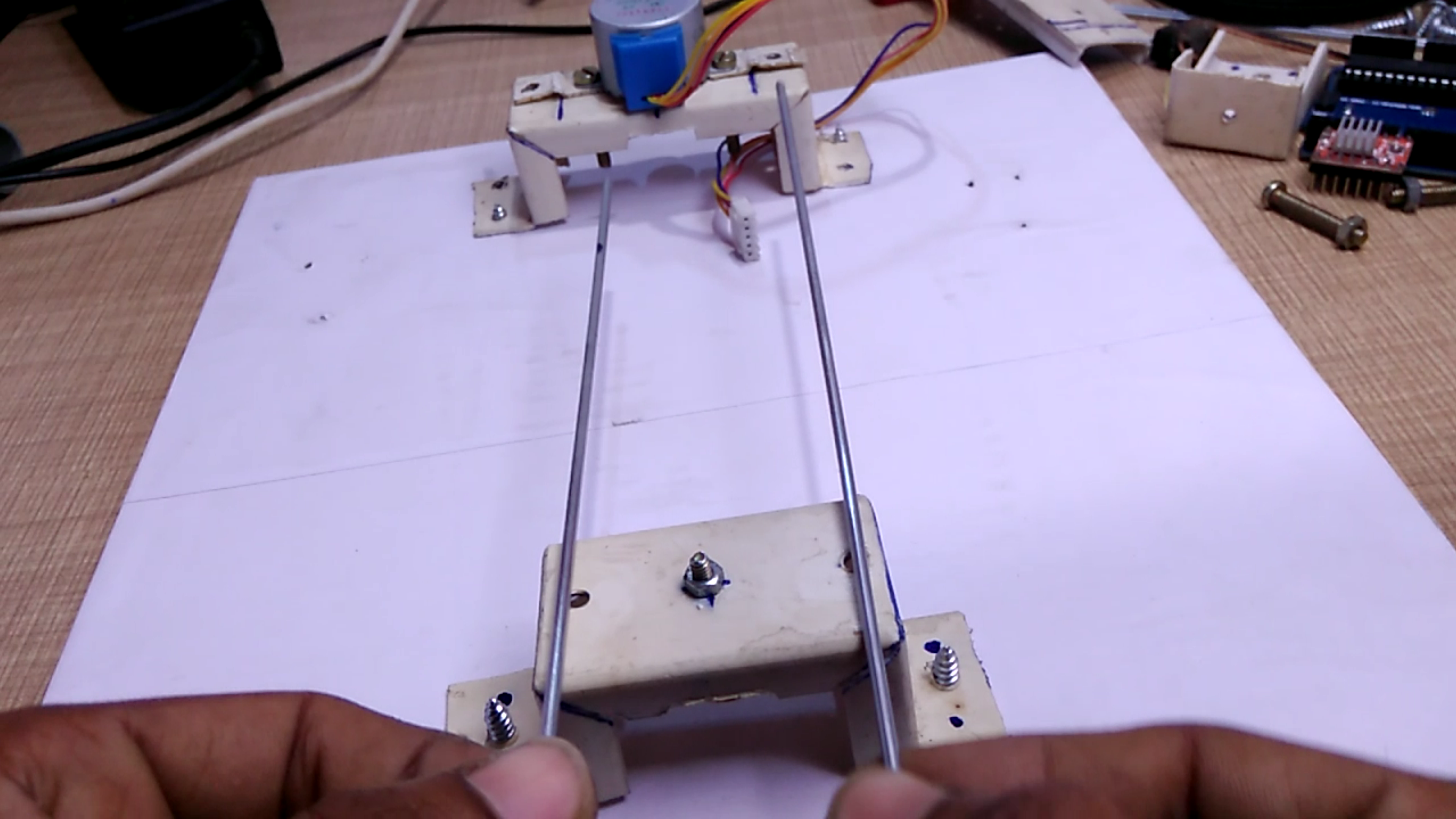
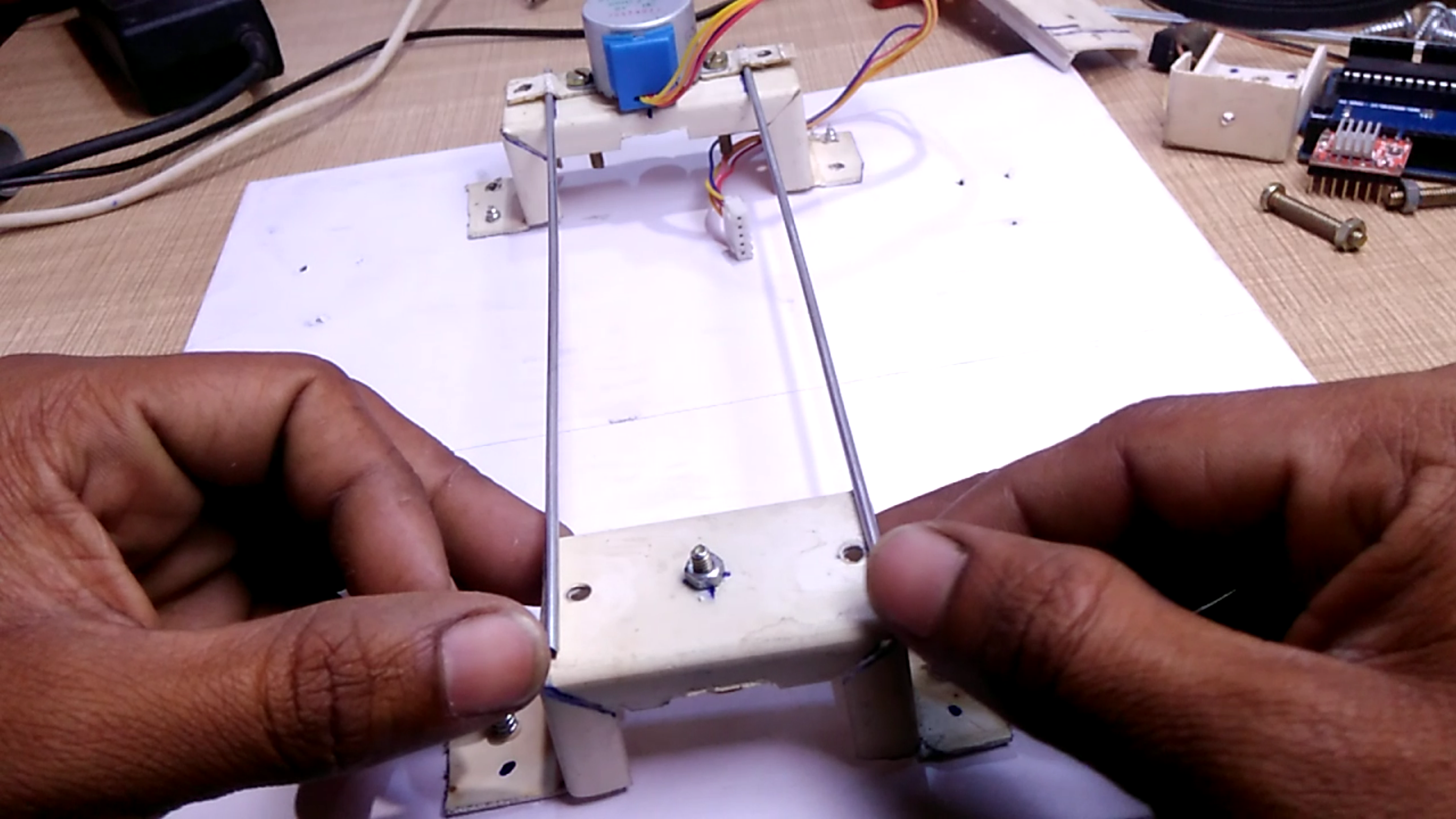
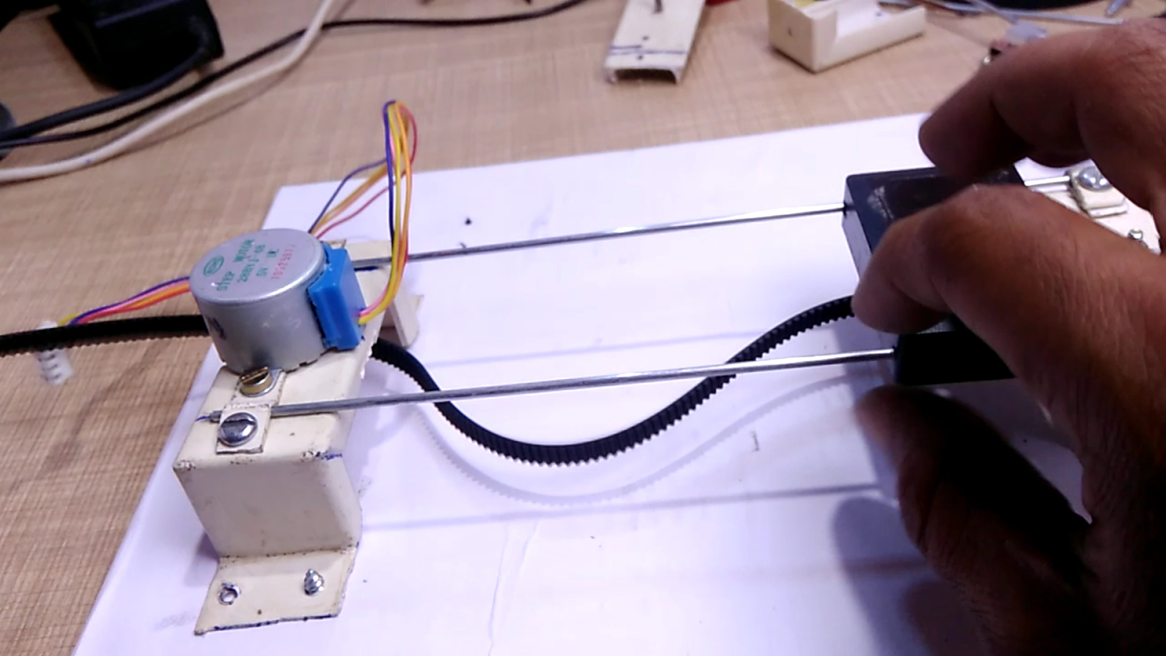
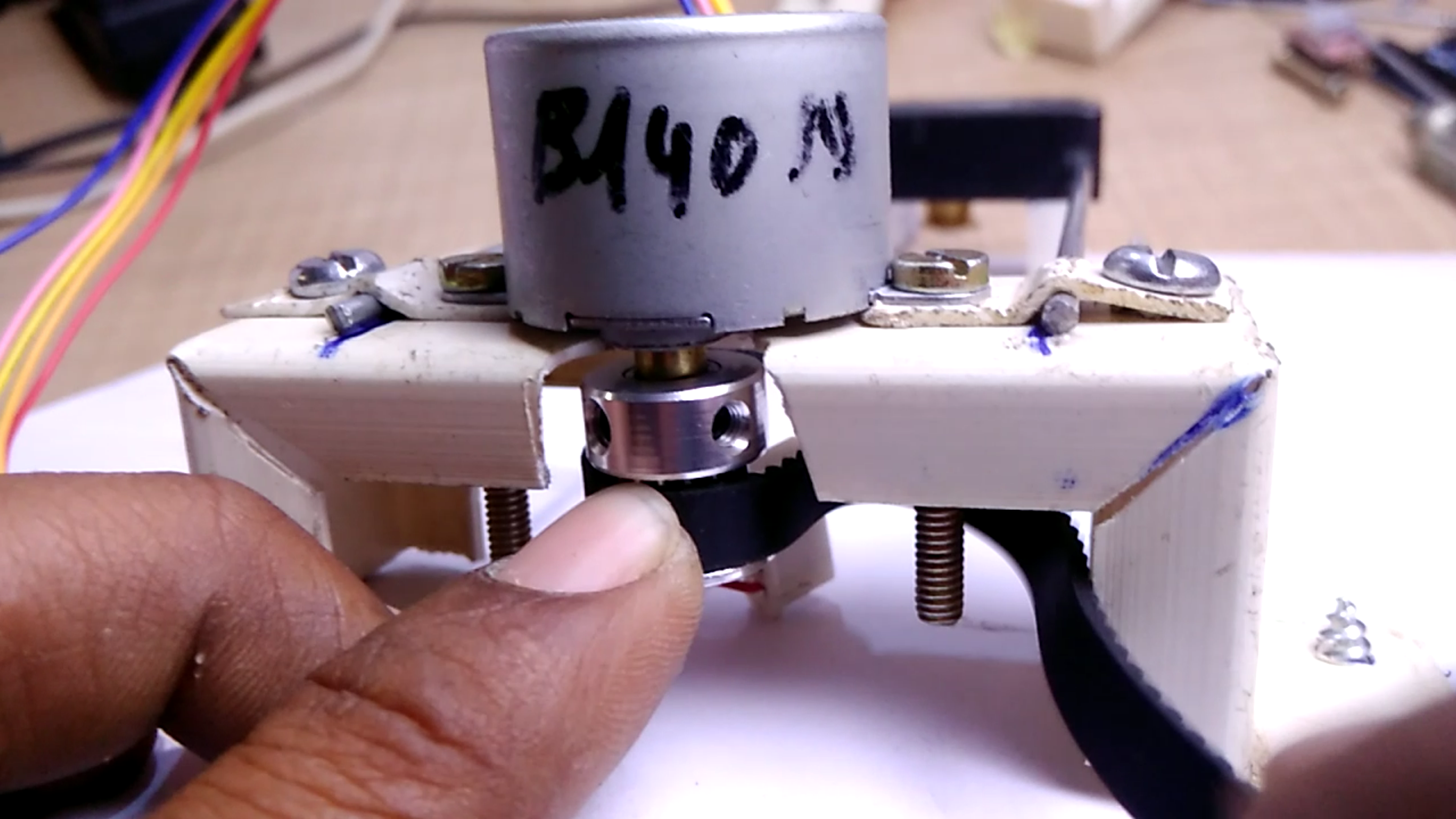
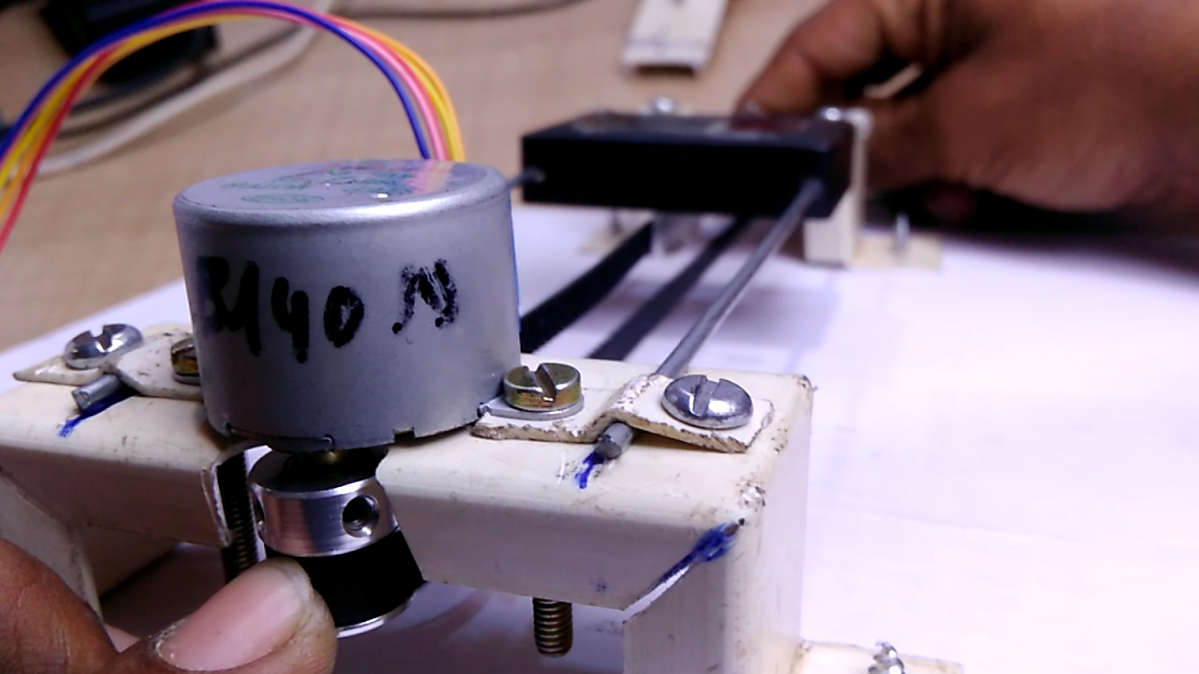
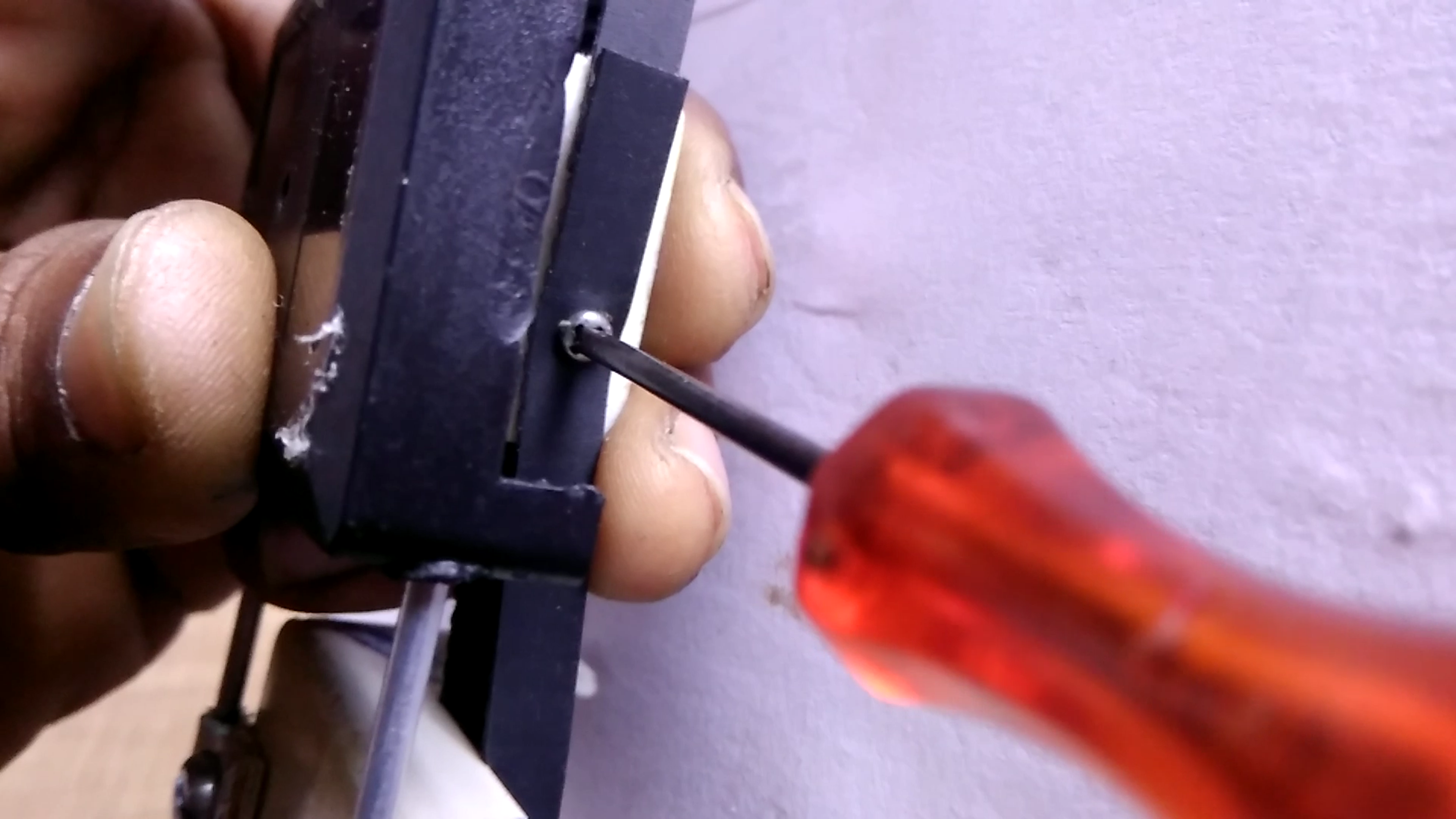
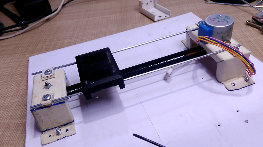
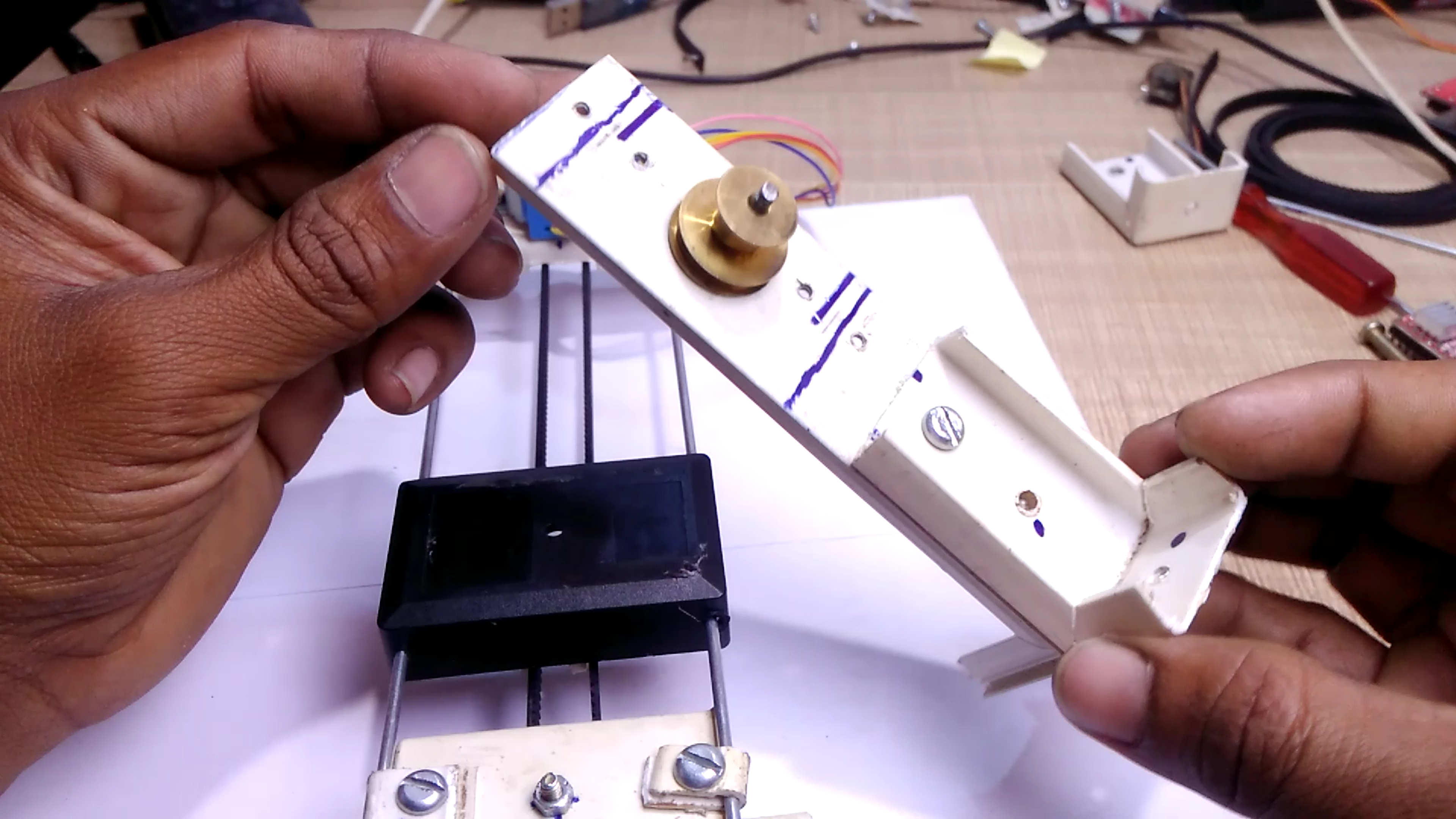
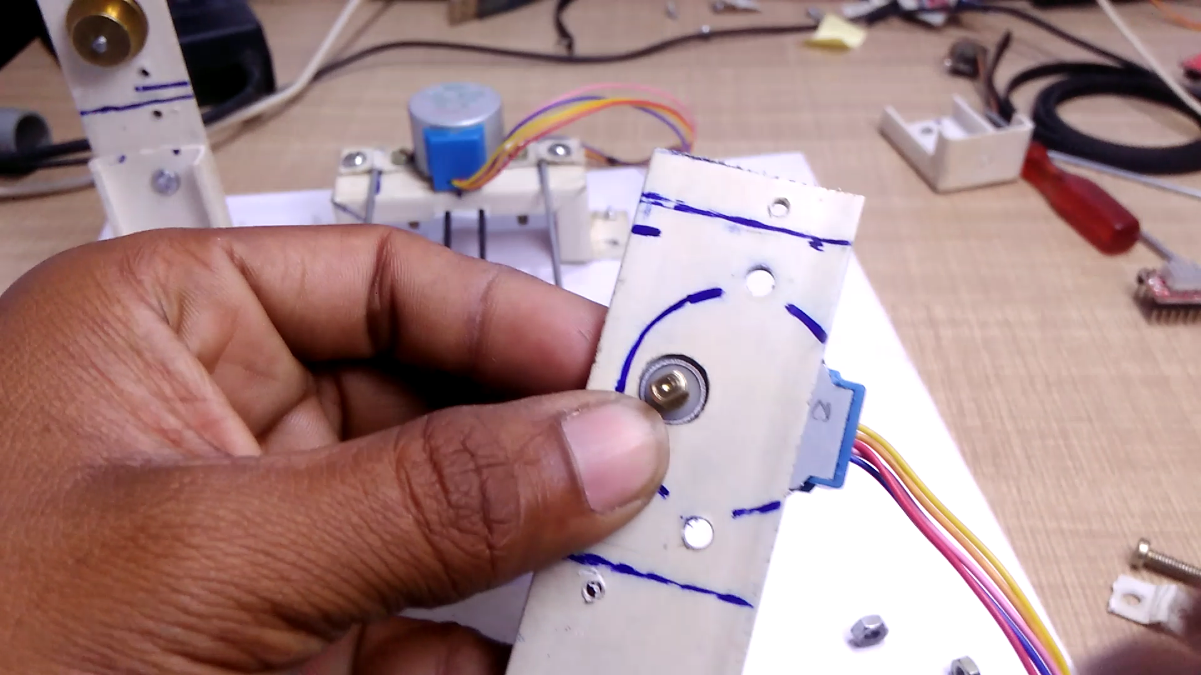
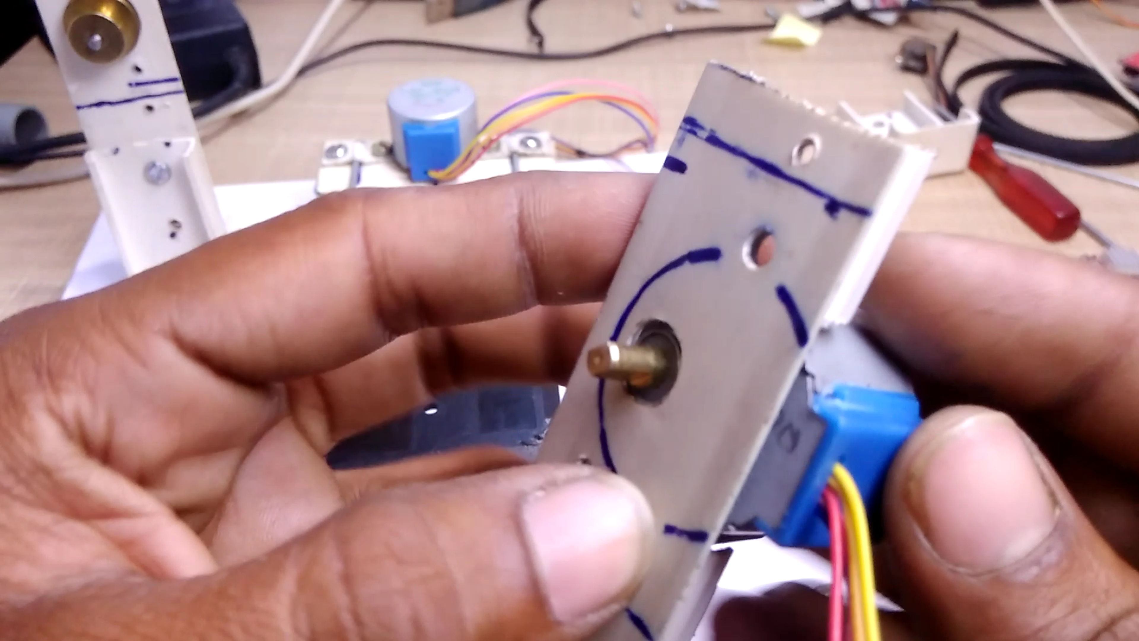
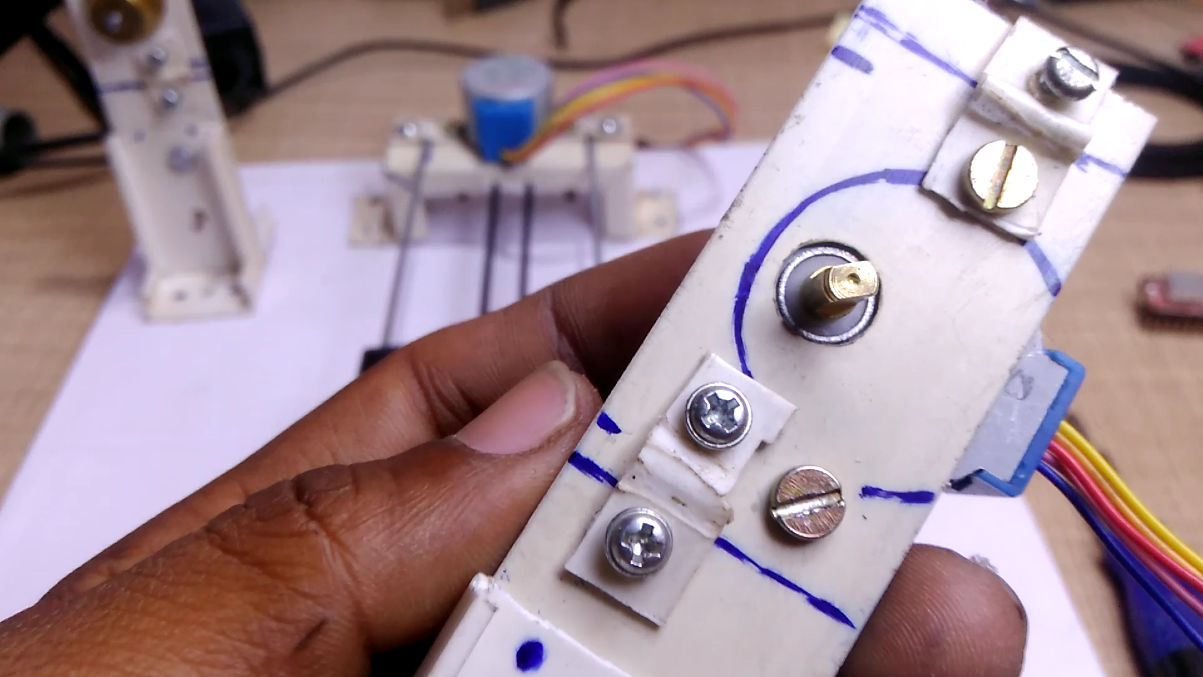
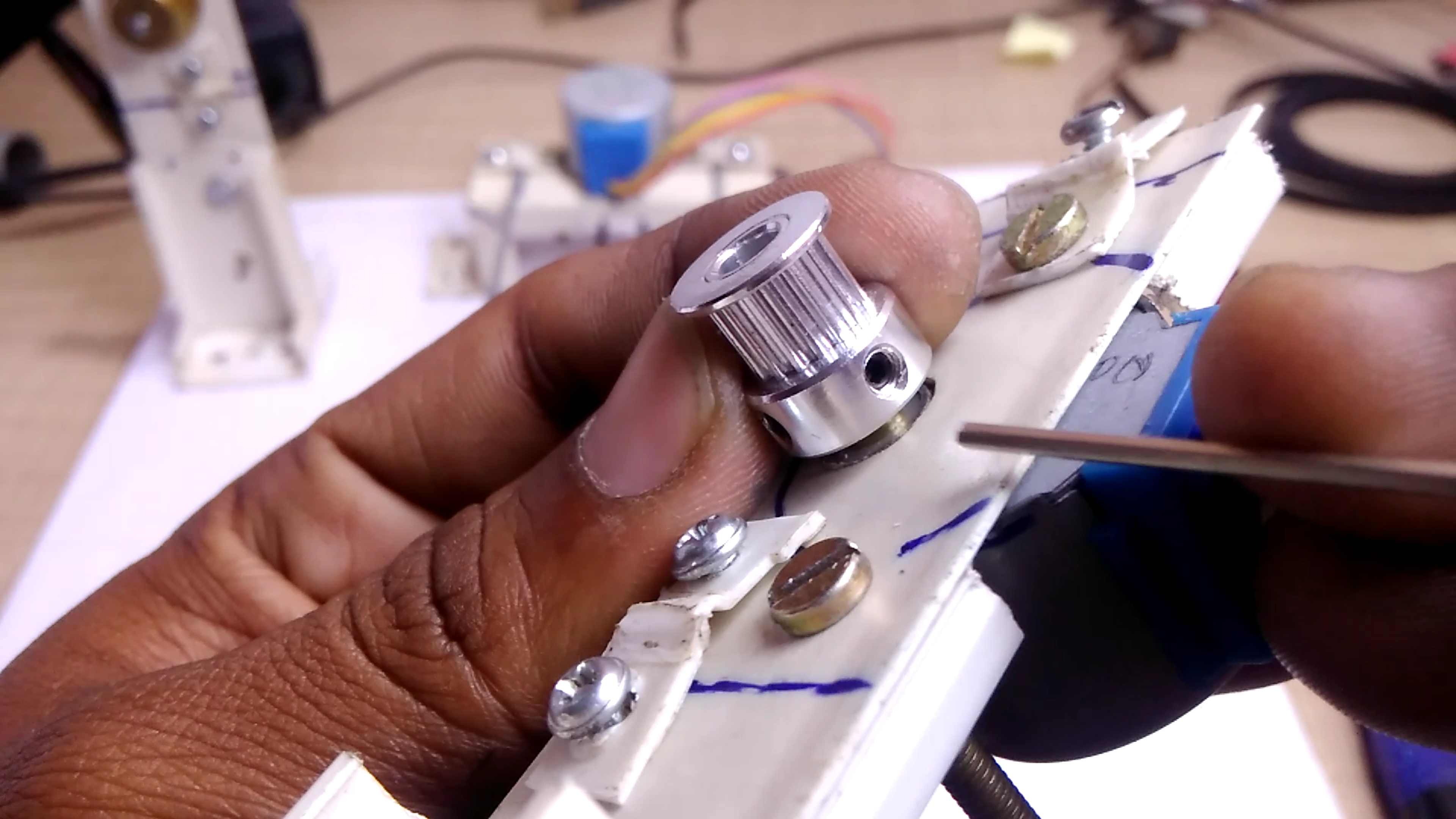
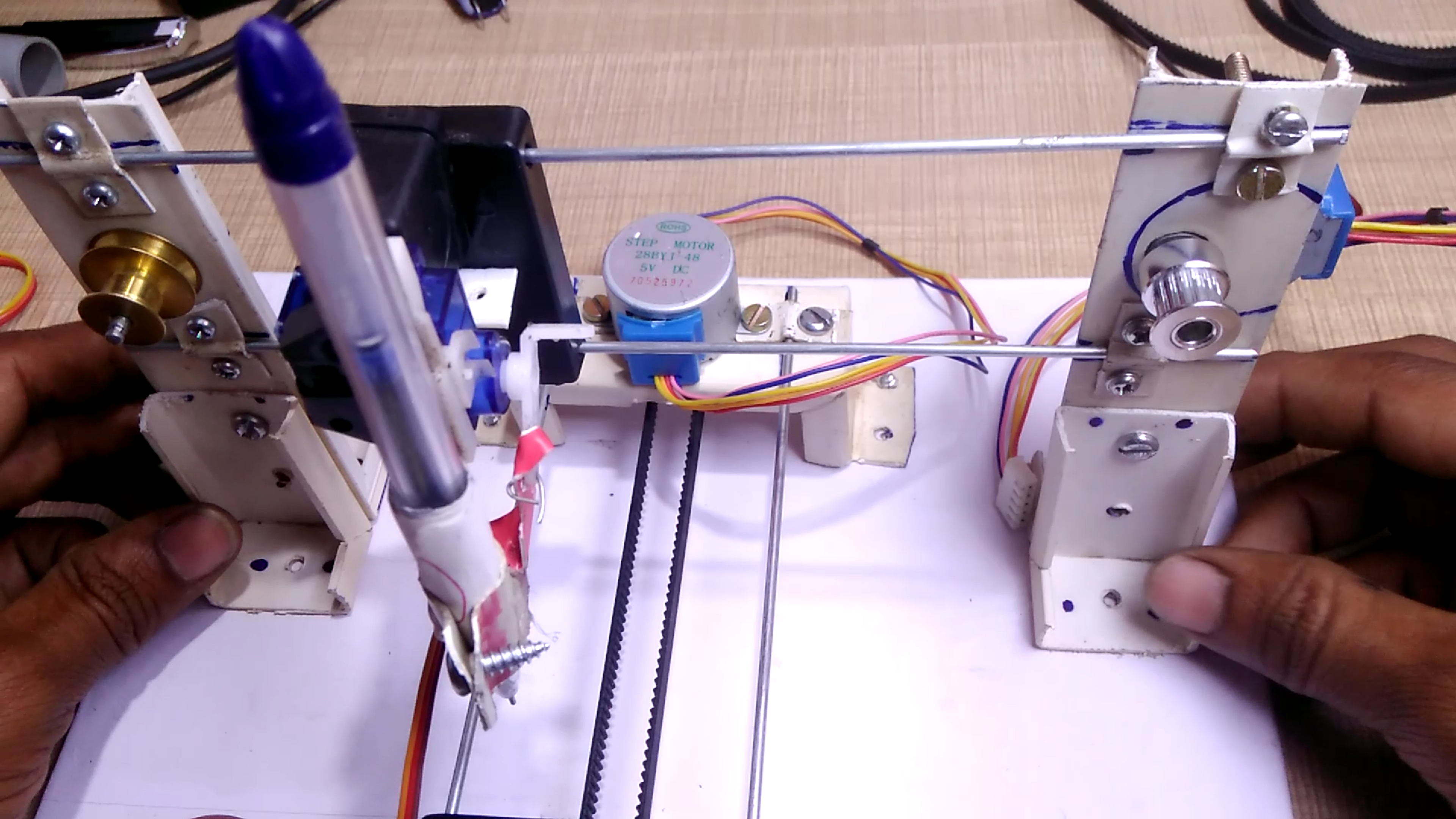
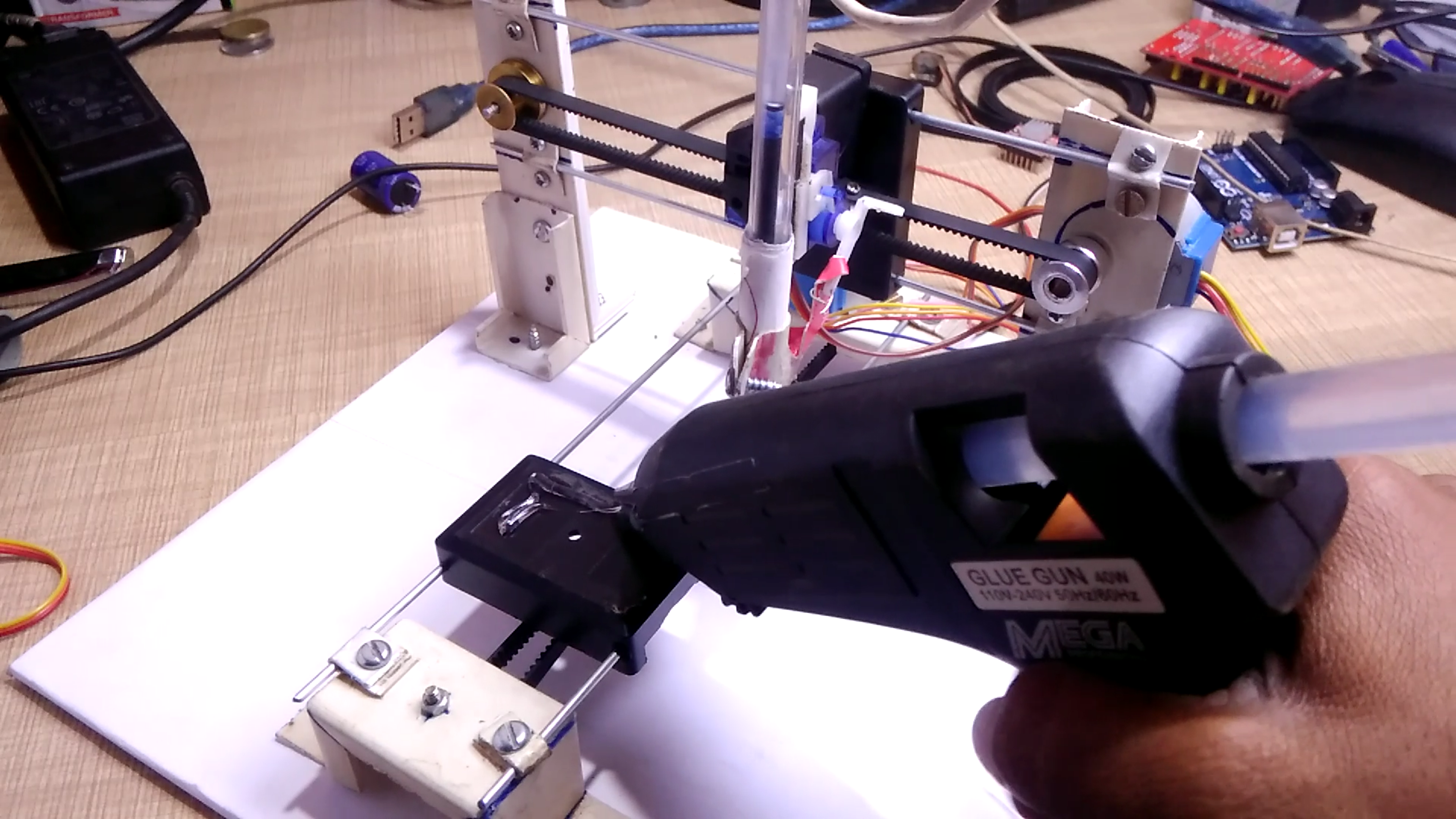
Assemble all the Parts on the pice of cardboard. check the video for more details
Electronics & Connections
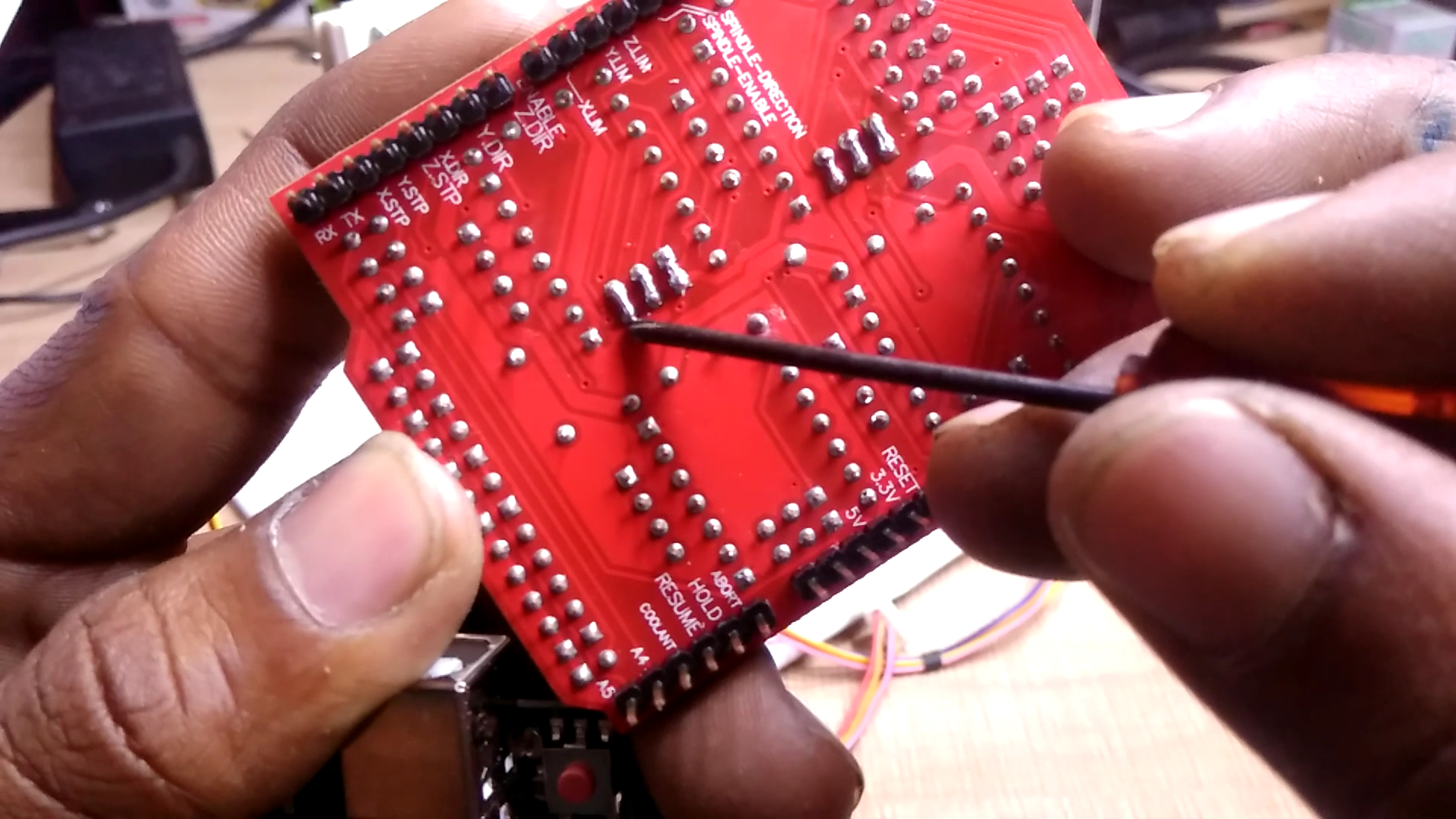
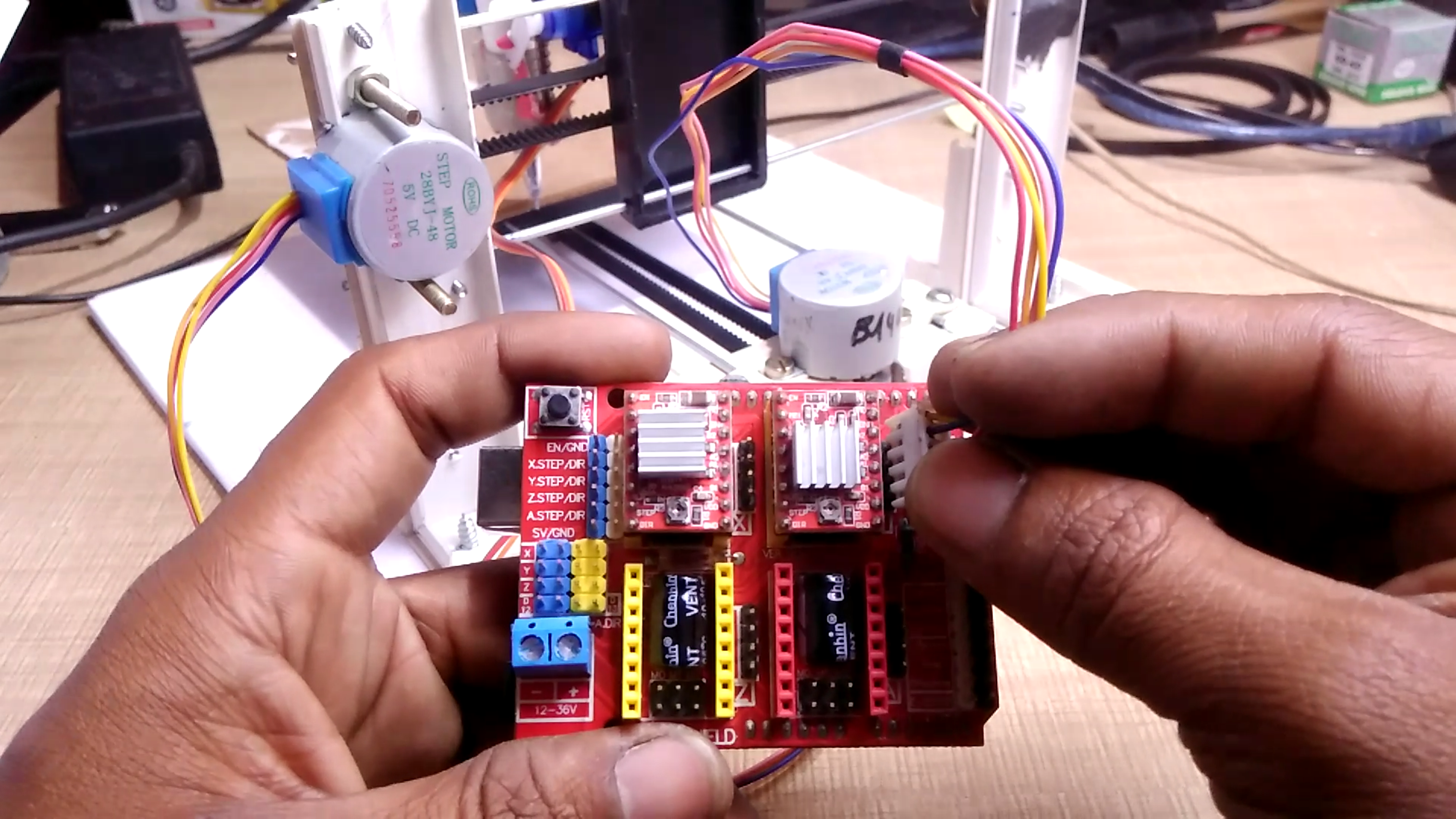
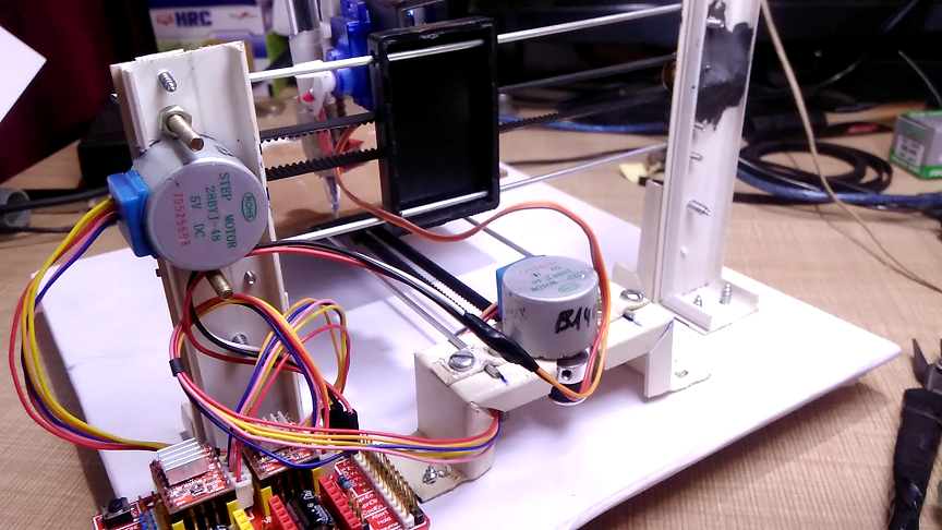
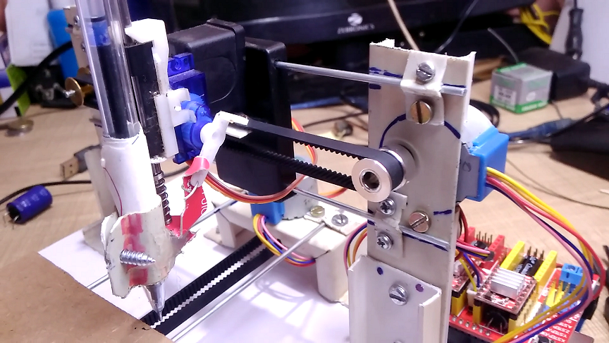
Now it's time to install all electronic parts and make connections.
First of all, we need to modify the motors connections and convert the motor into bipolar stepper motor, since the motor we are using is unipolar motor initially. and motor driver A4988 is not supported to the unipolar motor. so we need to modify its connections. It's very easy just follow the PDF from this link https://drive.google.com/file/d/1unQMJ9pxZ1_NVKVnq...
Enable the Micro stepping, to enable the micro-stepping take the CNC shield, and short the three pairs of the jumpers as shown in the picture.
Now Insert the Motor driver on the shield. while inserting them, make sure that the potentiometer on the driver module is facing inside of the shield. Take Arduino UNO and plug the shield on it carefully. Fix the Arduino on cardboard on a suitable position. plug x-axis stepper motors wires to the output of X-Axis motor driver and Y-axis stepper motors wires to the output of Y-Axis motor driver.
Coming towards the servo motor it has tree wires Brown-Red-Orange. The brown wire is ground, Red is Vcc 5Volt and orange one is the signal wire or input. Separate all these three wires from it's connector. Plug brown wire to the ground pin on the CNC shield, Red wire to the Vcc pin on the CNC shield and plug orange wire to the Z+ pin on the CNC shield.
And all connections are done.
Let's move towards the Programming part in next step
Upload GRBL Firmware to Arduino
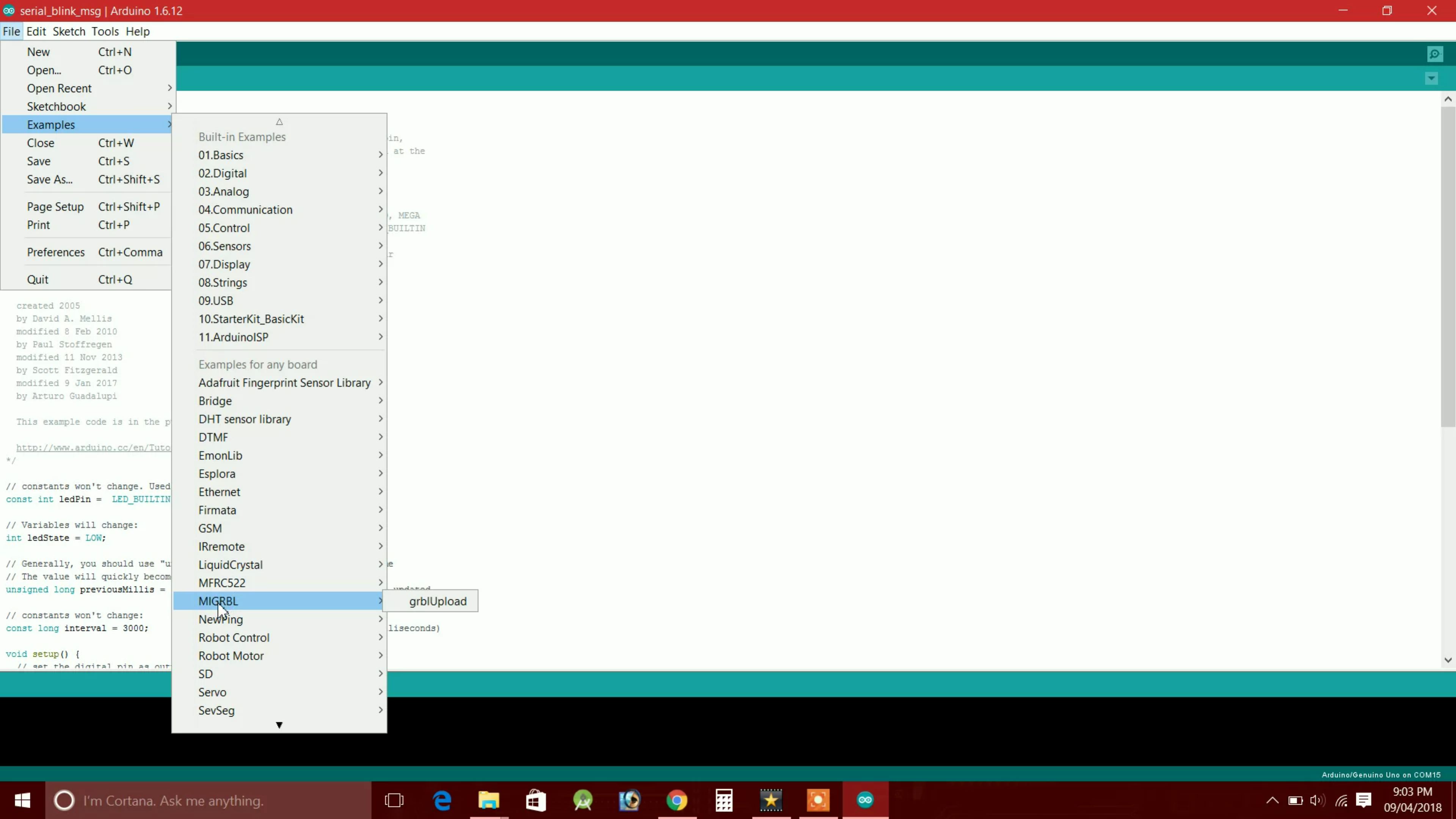
Note: Remove All previously installed GRBL libraries from your Arduino IDE.
Download The required Libraries from the following link
MIGRBL: https://www.mediafire.com/file/wxsy99vzdu6dlvg/MIG...
You will get a zip file from this link. extract it and it will create a folder by name MIGRBL. Copy this folder and go to the Arduino file location. To find Arduino file location right click on the Arduino Icon and click on open file location. Now go to the Libraries Folder and pest previously copied folder inside the Libraries folder. Now close it.
Restart the Arduino IDE, go to the file-examples, and search for MIGRBL. you will find a code by name "grblupload" inside the MIGRBL. Open it. Connect the Arduino UNO with your computer using USB cable. Select the correct com port and board type as Arduino UNO. And click the upload button. The Tx Rx LEDs on Arduino starts blinking while uploading the program. once the program is upload successfully all done.
Now the machine is ready
How to Make G-Code for This Machine?
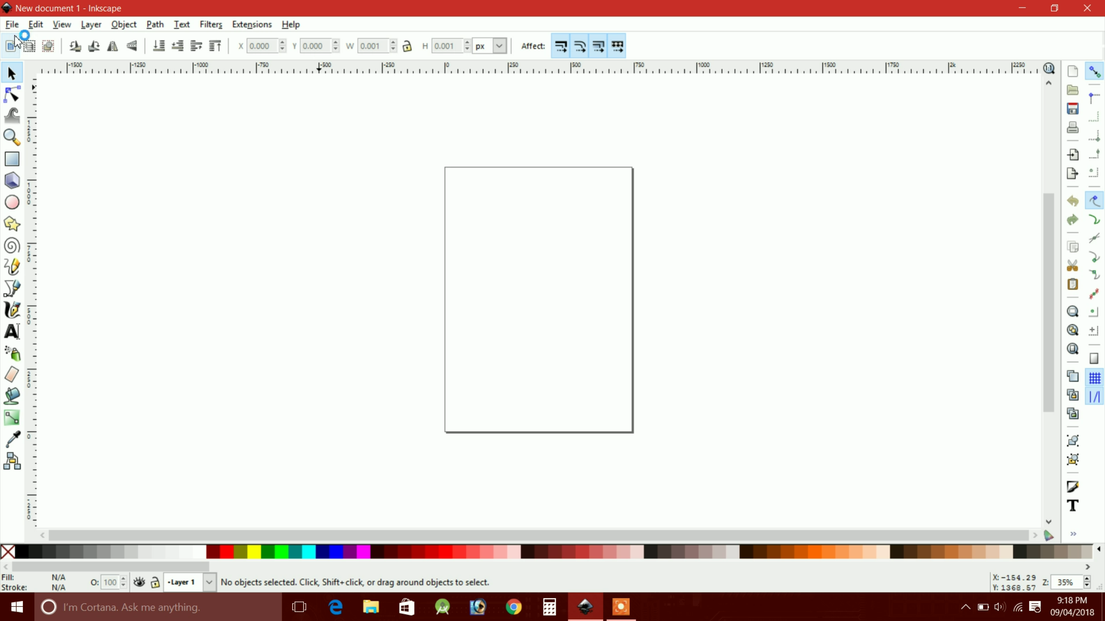
Let's see how we can make the G-Code for this machine. to make the G-Code we need a software name is Inkscape. Download Inkscape from this given link.
Inkscape 0.48.0: https://inkscape.org/gallery/item/7716/Inkscape-0....
Also, download the Mi Inkscape Extention: https://www.mediafire.com/file/9x1m60w1x6tdhaw/MI_...
After downloading the inkscape install it. now extract the Mi Inkscape Extention zip copy the folder created by the zip after extraction. Now open the file location of Inkscape and go to the folder share-extensions and pest the previously copied folder inside the extensions folder.
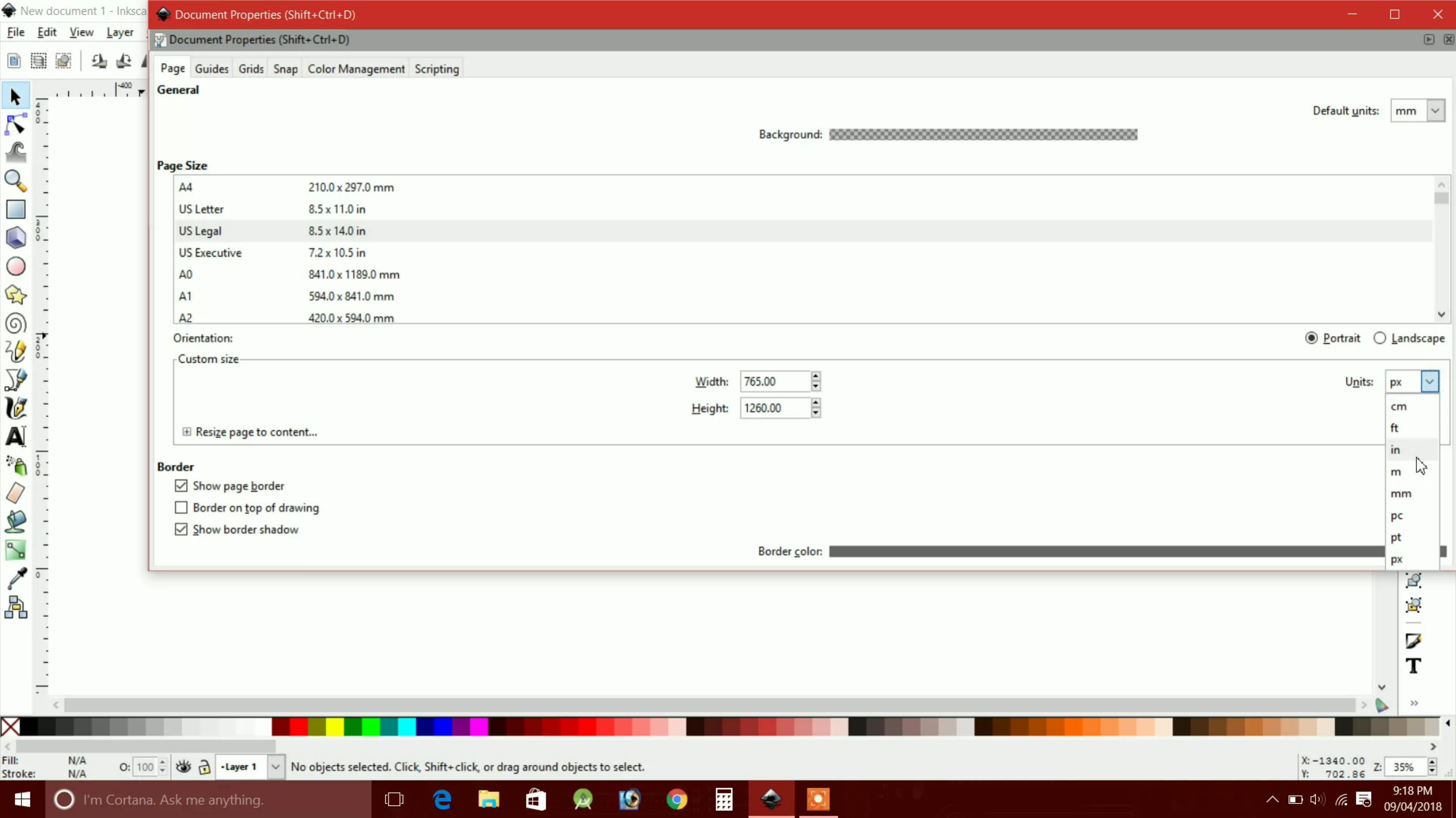
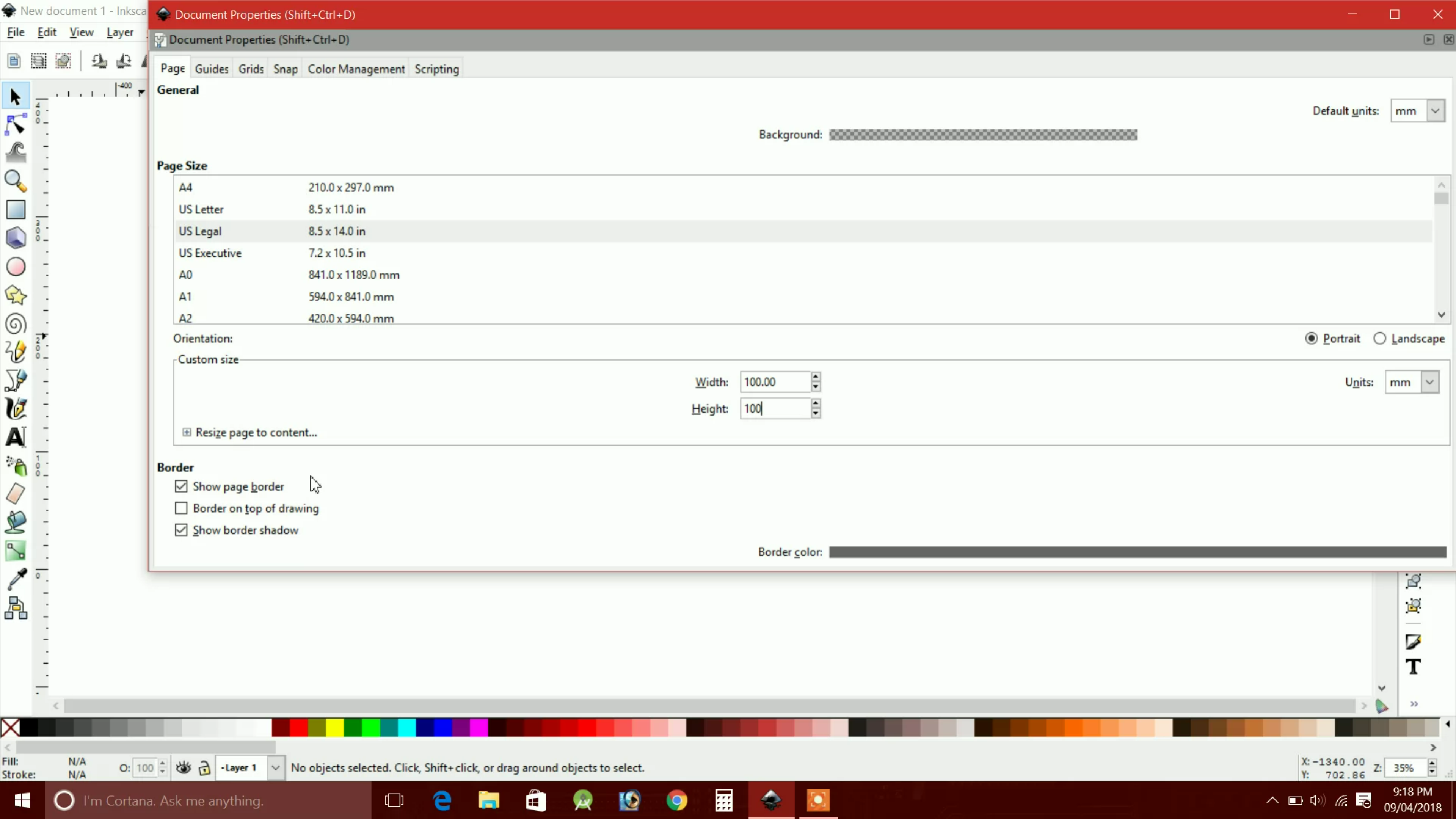
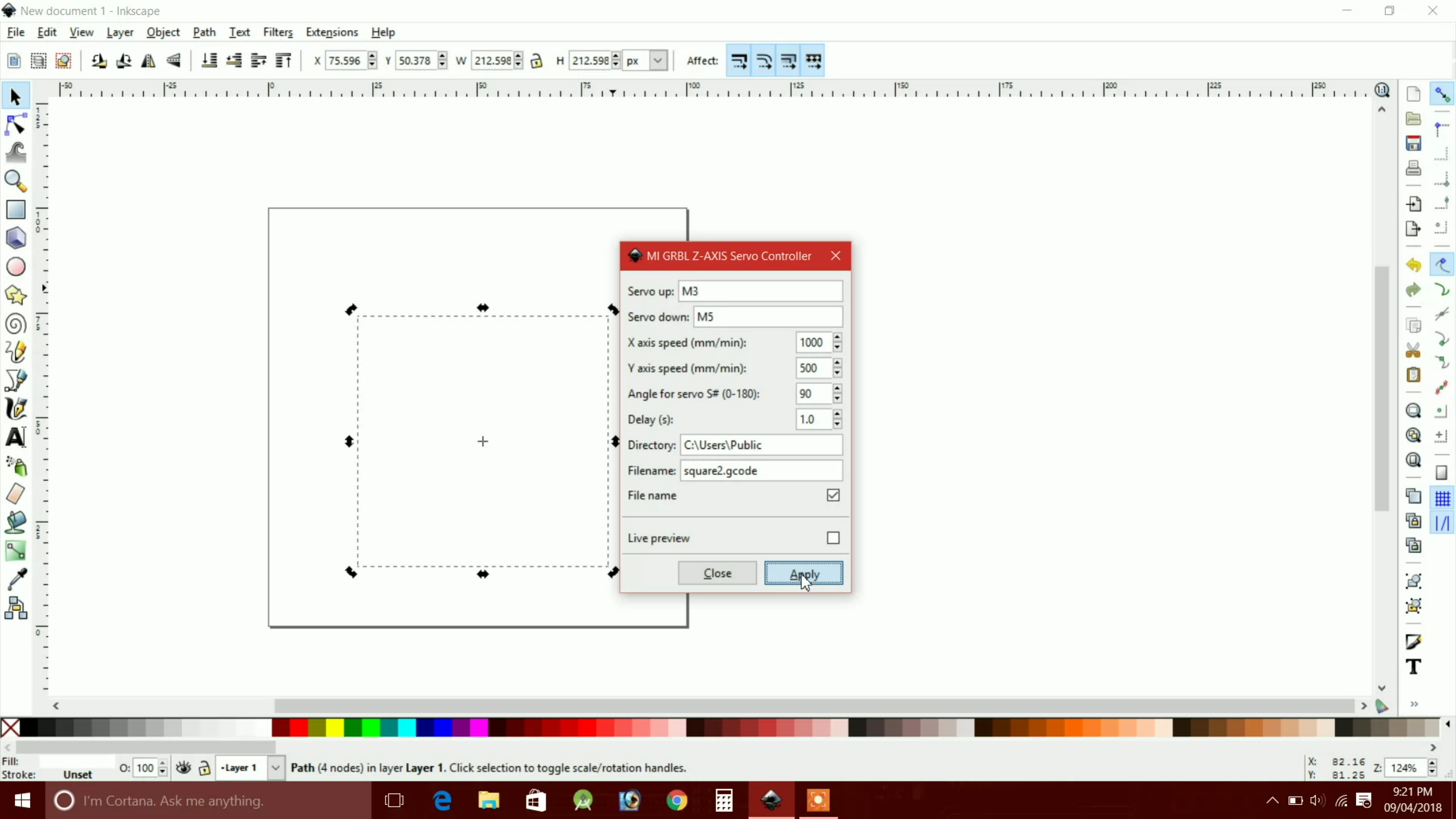
Now restart the Inkscape software. Go to the file, open document properties, a new window will popup. Set unit in mm also set your workplace area here. in this case, I'm going to set 100mm width and 100mm height since our machines max working space is 100x100mm. Now the area is set, let's make a very simple G-Code first. Select rectangle tool from the tool menu and draw a rectangle, let's draw the rectangle of 30x30mm, select the rectangle and go to path tab and click on object to path option, again go to the path tab and click the Dynamic Offset. Now go to the Extensions tab and click on the MI GRBL Z-Axis Servo. A new window will popup. check all parameters matching with a given picture or not. If not, set them as shown in the picture. and click apply G-Code will save on the given file location with the given name in the previous window.
How to Run Machine?
Download the GRBL Controller from here: http://www.mediafire.com/file/cg6z5ggb88wjbjo/Grbl...
Install it.
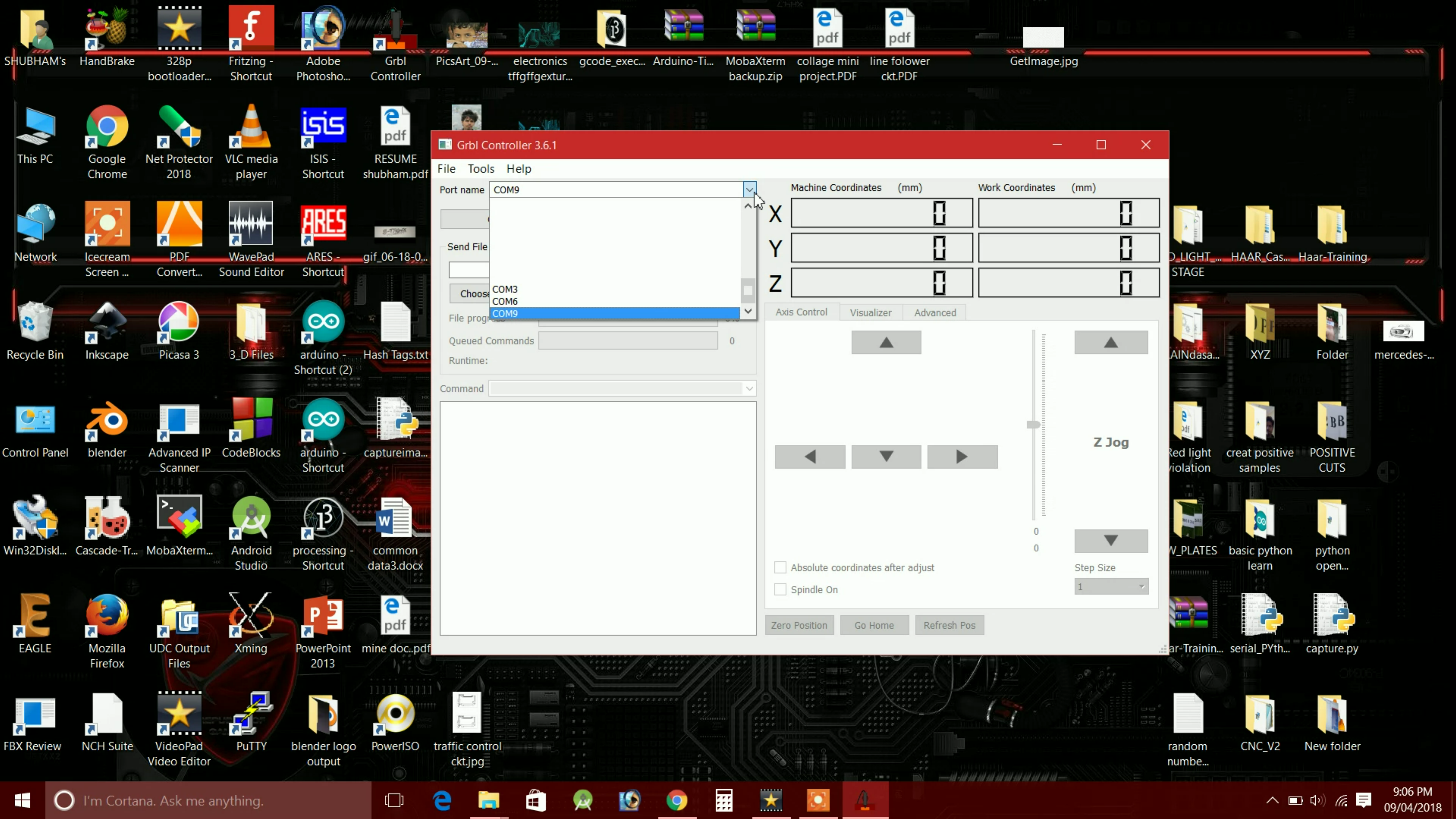
After the installation of GRBL Controller open it, in port name box select/type your COM Port on which your Arduino is connected. For example COM1, COM2, COM3, COM4....
After that set baud rate 115200. and click the Open button, if the machine gets successfully connected with PC the Open button turns into Orange color, if not it will return with some error code. Don't get panic if your machine not get connected with your PC, check the connections, and try again.
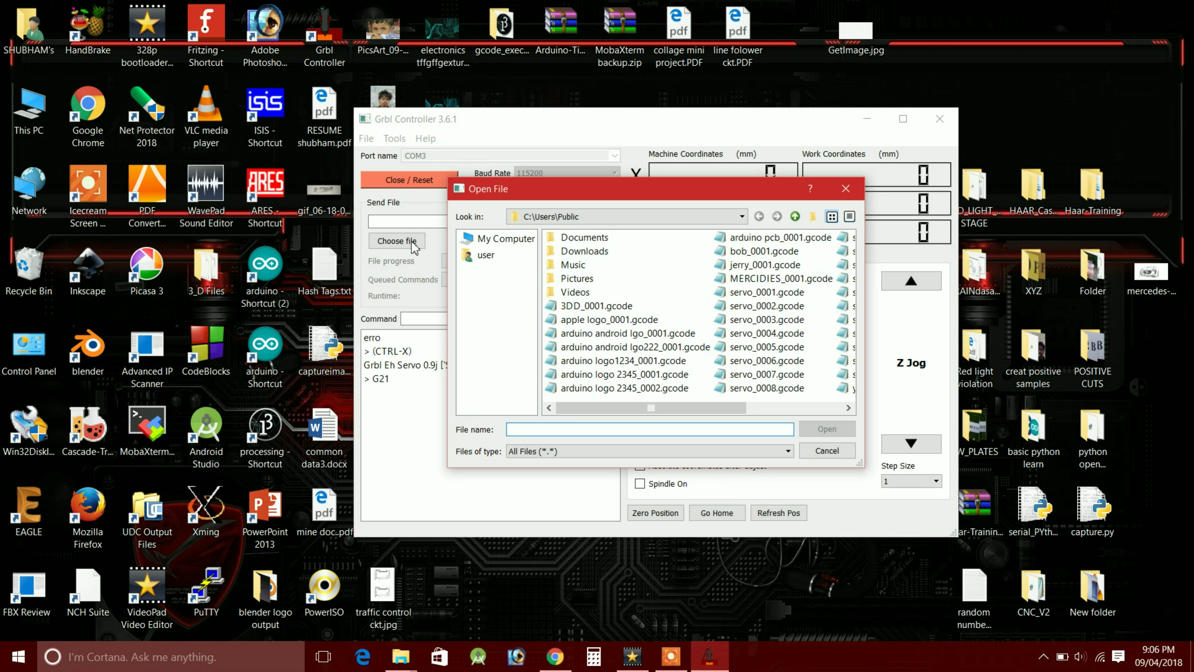
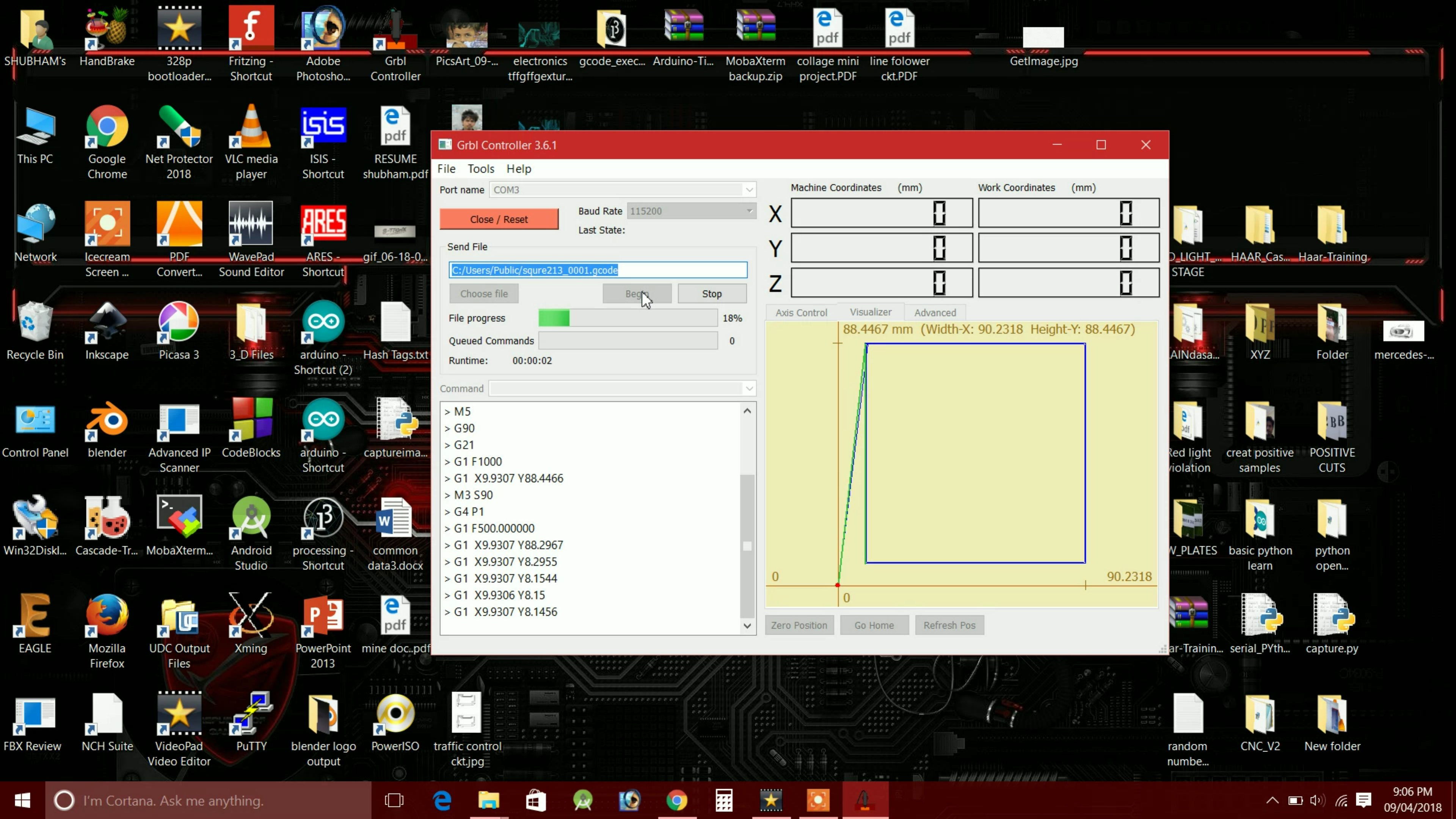
Once the machine gets connected with the PC. select the G-Code file which you want to draw. let's select the file which we created for drawing the square. And click begin machine start drawing. if the machine draws the smaller square than its actual size which you set while making the G-code, it means you need to increase steps counts for mm for X & Y-axis. T do that go to command box and type $100 = 450 this is the command for x-axis here $100 denotes the X-Axis and 450 is the number of steps. D this for Y-Axis also, for y-axis type $101=450.
Note that 450 is not the standard value. you have to take this value according to the difference between your drawing's actual size and output size. If the output size is less than the actual size increase the number of steps for both axis.
And all done.
If you have any doubts regarding this project feel free to ask questions in the comment box.
Hope you find this useful. if yes, like it, share it, comment your doubt. For more such projects, follow me! Support my channel on YouTube.
Thank you!
SUBSCRIBE My YOUTUBE Channel