GOOGLE HOME Visualization Effect LED (How to Make)
by HappyThingsMaker in Circuits > LEDs
5400 Views, 40 Favorites, 0 Comments
GOOGLE HOME Visualization Effect LED (How to Make)
![[How to make] google home visualization effect LED light (step by step, arduino)](/proxy/?url=https://content.instructables.com/FY7/8OIW/JEIV9QM5/FY78OIWJEIV9QM5.jpg&filename=[How to make] google home visualization effect LED light (step by step, arduino))
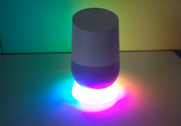
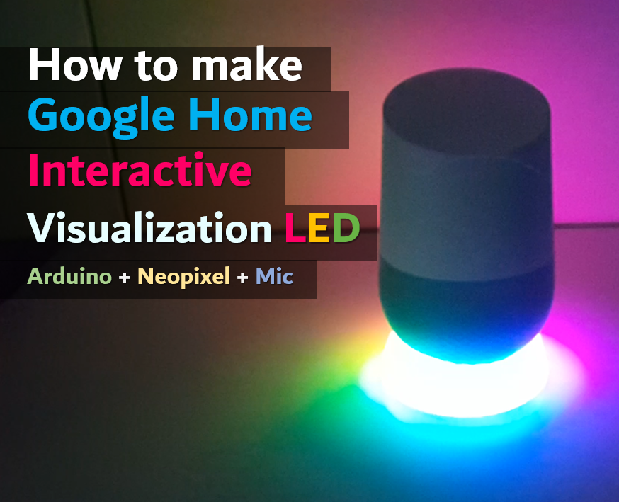
DANCING LIGHTS
The LED light dances to music from Google Home. The light has a kind of Arduino, LED ring and a microphone sensor. I printed the case by using 3d printer.
I think music is more fun when the other effects are added on it.
All parts and source code are opensource. Why don't you try it by yourselves?
Overall Information
- Manual https://sites.google.com/view/100happythings/17-g...
- Source Code https://github.com/happythingsmaker/GoogleHomeLED
- 3D printing files https://www.thingiverse.com/thing:2817612
[ About the maker ]
- Youtube Channel https://www.youtube.com/EunchanPark
[ Parts ]
(Click with Shift key for pop up loading)
- 1 x Digispark ATtiny85 board https://goo.gl/tcWX2Q
- 1 x MIC Sensor (MAX4466) https://goo.gl/rPfzwf
- 1 x Pin header https://goo.gl/DowpKL
- 1 x ff dupont cable set https://goo.gl/Ygt9nj
- 1 x WS2812b LED 24 Ring https://goo.gl/gH6YTv
- 1 x Capacitors (4700 uF, 10V) https://goo.gl/JAQjMf
[ Tools ]
- 3d printer (Anet A8) https://goo.gl/XY4Lgw
- Filament for 3d print (PLA 1.75mm) https://goo.gl/gAKzTt
- Wire Nipper https://goo.gl/L9pQQN
- Wire Stipper https://goo.gl/qKXKwJ
- Hot melt glue gun https://goo.gl/z67NkU
- Screw Driver (+) https://goo.gl/6ojbgb
- Electronic Tape https://goo.gl/fJC7yv
- Soldering Tools(Hakko) https://goo.gl/ojZUkF
- Soldering Hand https://goo.gl/UjNFYm
DOWNLOAD - SOFTWARE CODES
https://github.com/happythingsmaker/GoogleHomeLED
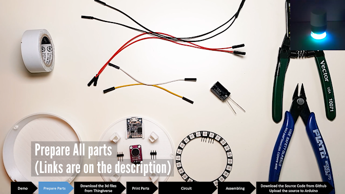
PREPARE ALL PARTS
You will need to print 3d parts by using 3d printer.
If you don't have one, find somewhere that has a 3D printer around your place. Fablab or maker space must have 3d printer.
DOWNLOAD 3D FILES AND PRINT IT
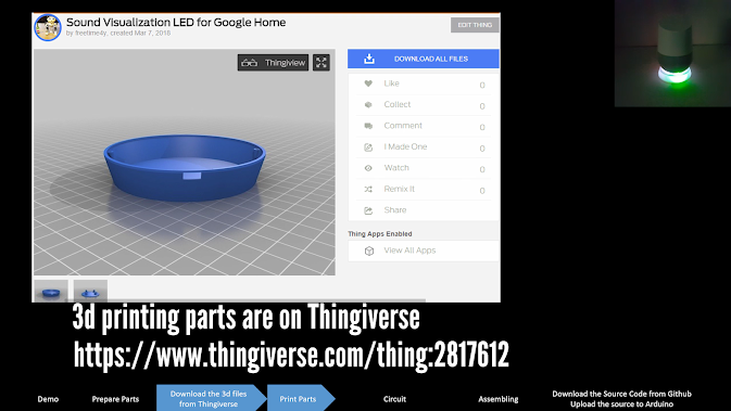
https://www.thingiverse.com/thing:2817612
Thingiverse is one of most popular platform. Anyone can upload and download 3d printing models.
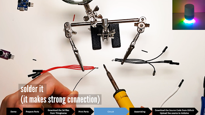
SOLDER PIN HEADERS
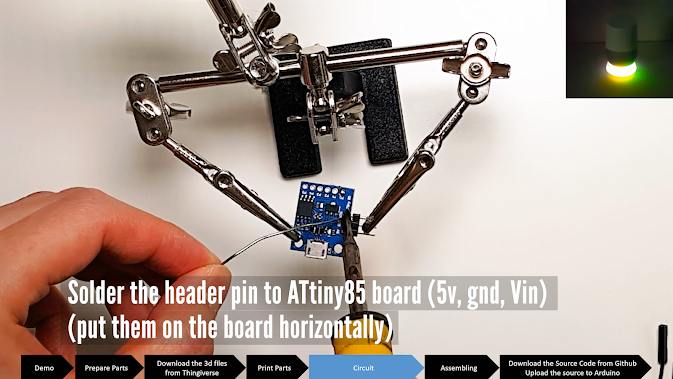
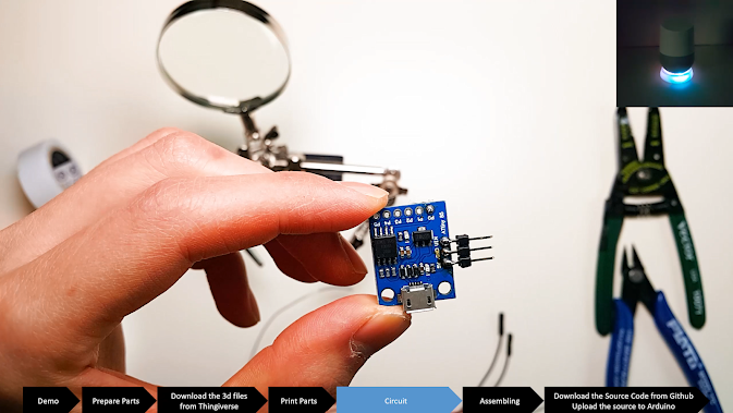
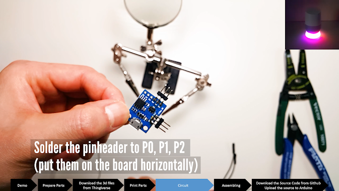
Pin headers are for connecting conveniently between a board and cables. Normally, pins are put onto the board.
This time, I put it horizontally because the board needs to be laid on the 3d printed bottom frame.
That soldering way saves space.
SOLDER THE MICROPHONE PART
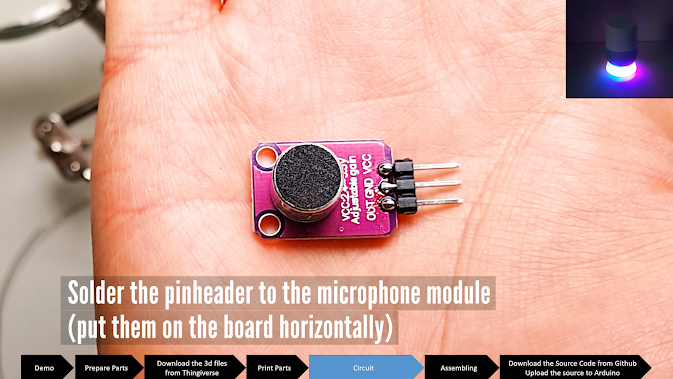
It is same way. Put the header pins on the board horizontally and solder it carefully.
SOLDER THE LED RING
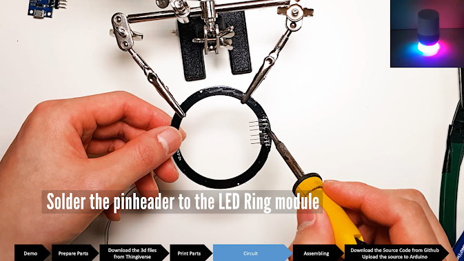
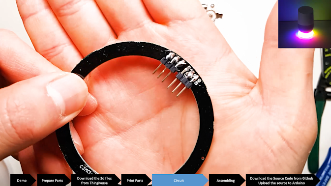
It is same way. Put the header pins on the board horizontally and solder it carefully.
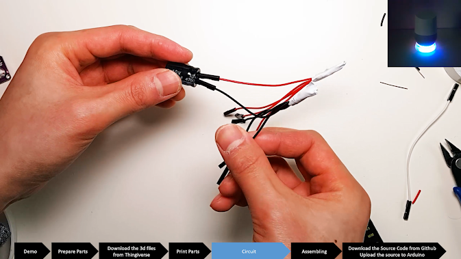
MAKING a CABLES
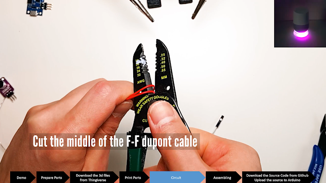
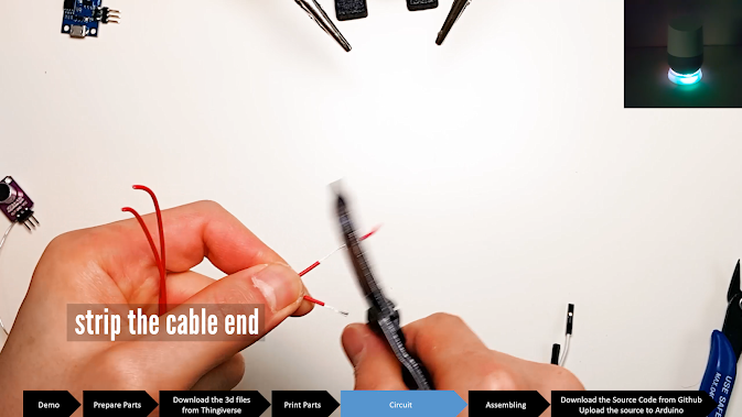
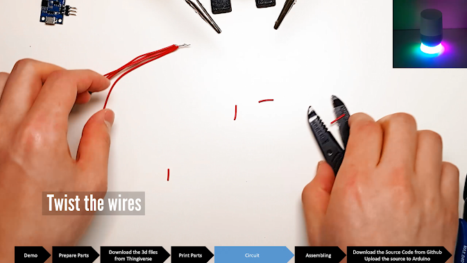
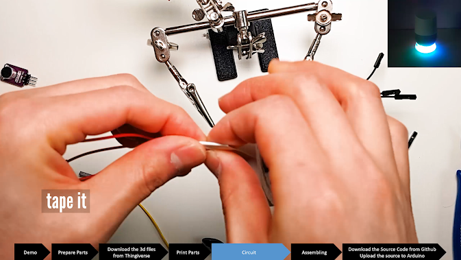
All VCC parts are needed to connect together. There are many ways to tie them together. In this tutorial, I just make some cables.
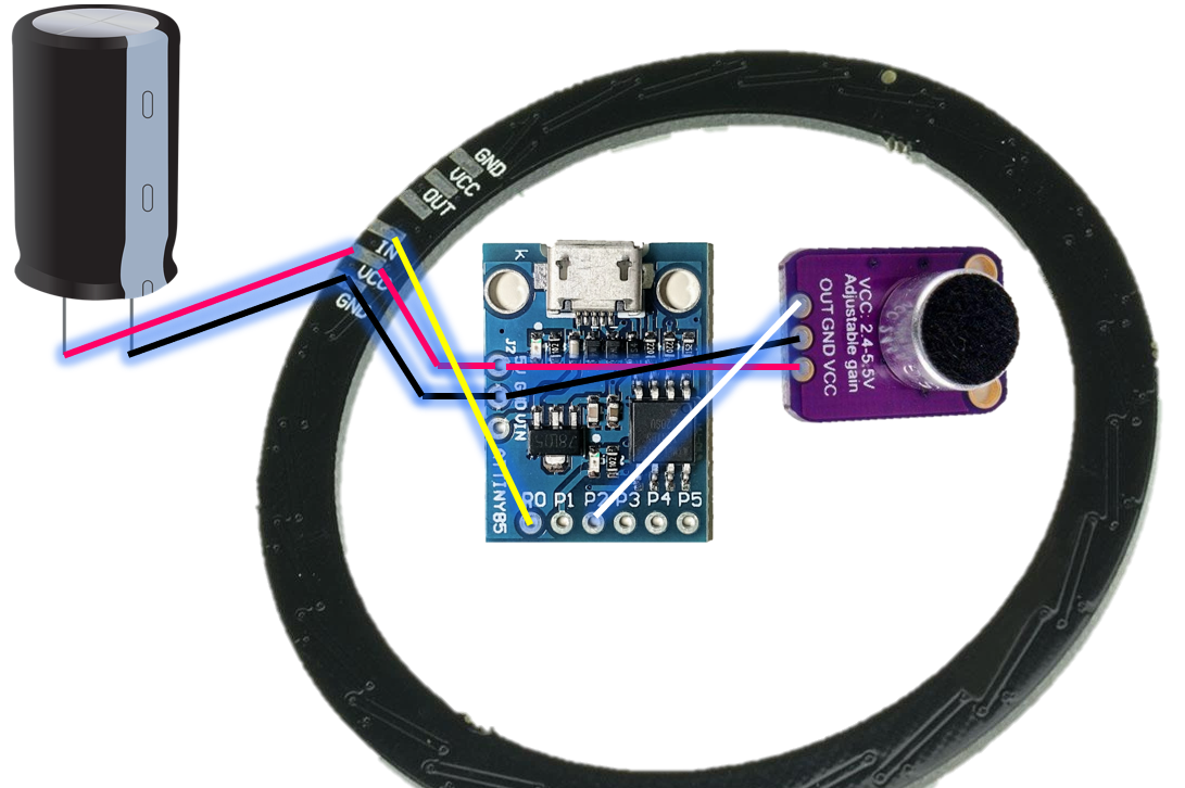
OVERALL CIRCUIT SCHEMATIC
CAPACITOR
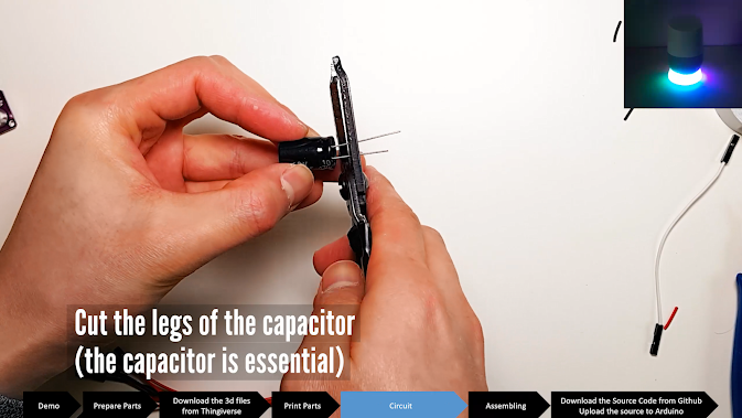
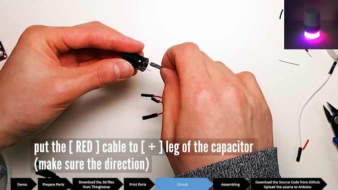
The reason I use the capacitor is for stabilizing the power. In the middle of developing this work, I got some problem reading sensor value. It turned out the problem was from the LED. The LED ring has 24 * 3 color LEDs. They consume a lot of power and every time they are turned on, the power over the circuit is dramatically down. That makes a large mount of noise.
The capacitor prevents from the noise and sudden power consuming.
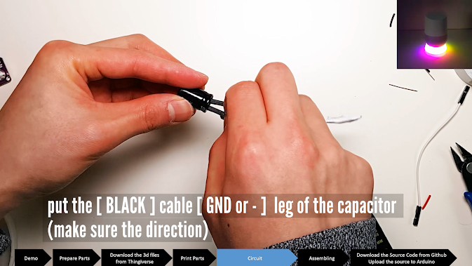
You need to be careful about the direction. The capacitor has 2 poles. Positive pole must be connected with VCC and negative must be connected with GND.
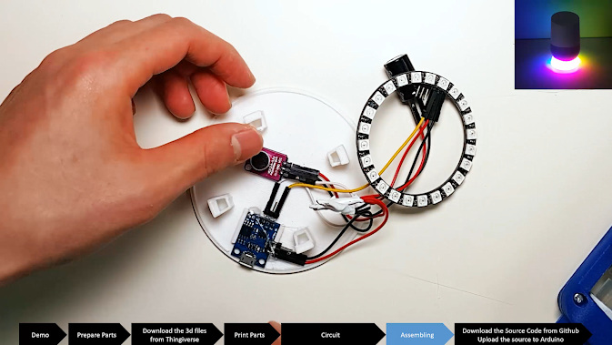
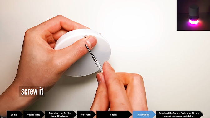
ASSEMBLE THE BOARD AND THE FRAME
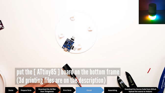
Now, put the board on the frame and assemble cables.
Be careful because the USB plug may not be inserted depending on the position of the board.
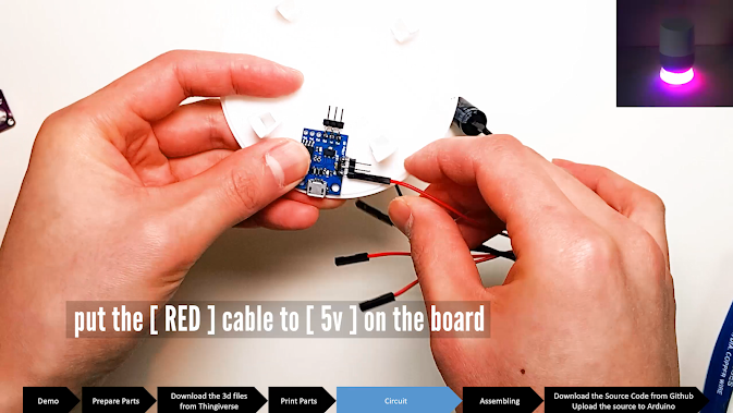
Insert the "Red" Cable to 5v on the Board
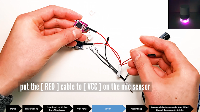
Insert Red Cable on the VCC on the Microphone
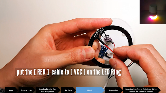
Insert the Red Cable on the LED's Vcc
Insert the Black Cable to the GND of the LED Board
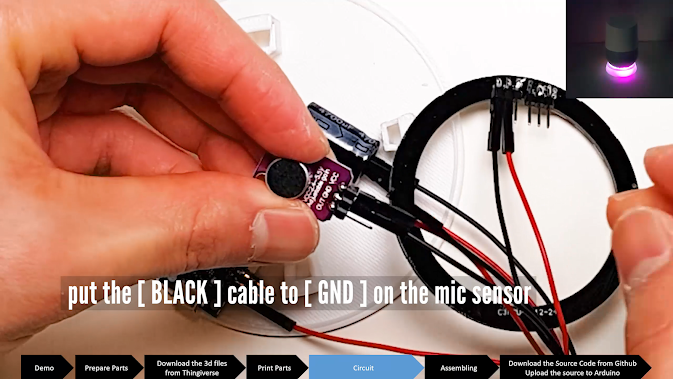
Insert the Black Cable to the GND of the Mic Board
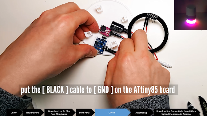
Insert the Black Cable to the GND of the ATtiny85 Board
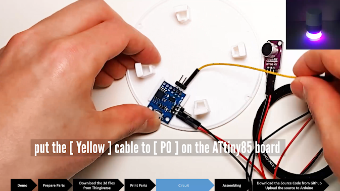
Insert the Yellow Cable to the P0 of the Board
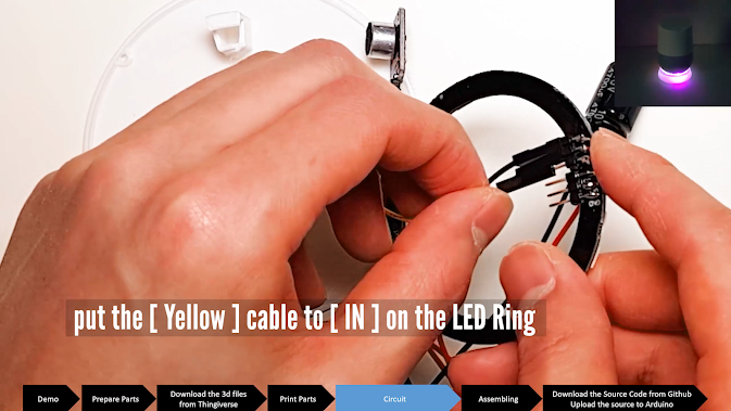
Insert That Yellow Cable to in of the LED Board
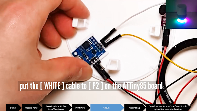
Put the White Cable to P2 of the Board
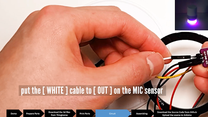
Put the White Cable to "OUT" of the Mic Board
GLUE IT
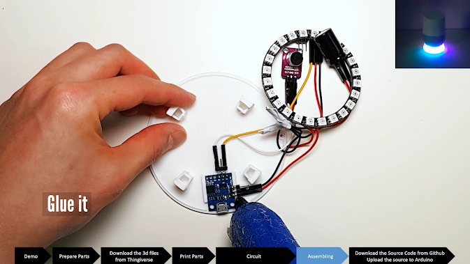
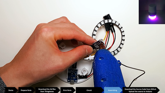
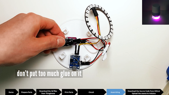
You may need to adjust the location again, so glue it a little
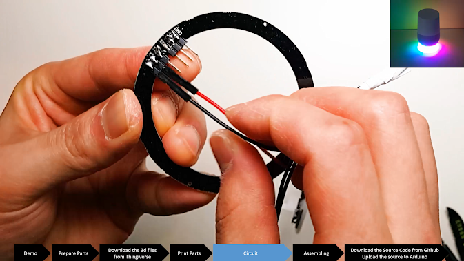
ASSEMBLE THE LED RING ON THE FRAME.
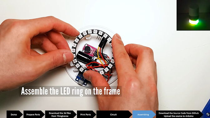
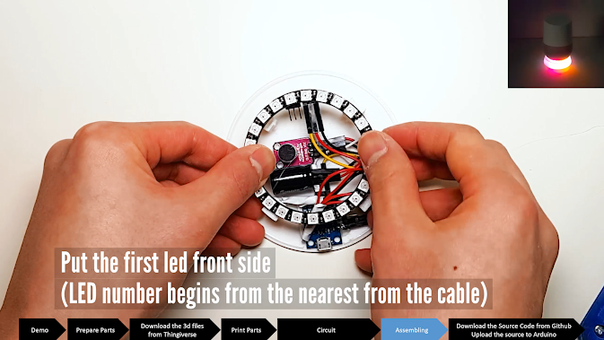
The frame has hooks so you don't need to put any glue on it.
COVER IT
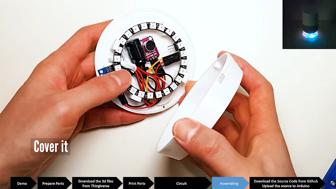
If you want to change the color, I recommend you to print "natural" color or white.
HOW TO INSTALL a LIBRARY
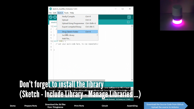
Sketch - Include Library - Manage Libraries ...
Search "Neopixel" and Install it
DOWNLOAD THE SOURCE CODE AND UPLOAD IT ON YOUR BOARD
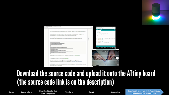
Download the source code here
https://github.com/happythingsmaker/GoogleHomeLED
ATtiny85 is slightly different from other Arduino.
Please refer this video.