GOMU GOMU NO MI With XIAO RP2040
by Arnov Sharma in Circuits > Art
2741 Views, 10 Favorites, 0 Comments
GOMU GOMU NO MI With XIAO RP2040

.gif)


Hello, fellow makers! Here is something fun: a glowing GOMU GOMU NO MI, also known as the GUM GUM FRUIT, created entirely of PCBs.
Here, RGB LEDs and an XIAO RP2040 DEV board are used. Two PCBs are utilized: the bottom board, which contains the RGB LEDs and XIAO Board, and the top board, which lacks components but has an etch layer added in the form and design of a gum-gum fruit.
This second board diffuses the LEDs' glow, which is visible, and gives the PCB setup as a whole a glowing appearance.
For those of you who are unfamiliar with the GUM GUM Fruit, also known as Gomu Gomu no Mi, it is a made-up fruit that appears in the well-known Japanese manga and anime series One Piece, which was developed by Eiichiro Oda. In the world of One Piece, it is one of many "Devil Fruits." Devil Fruits are enigmatic and elusive fruits that, when consumed, endow the eater with exceptional powers but also rob them of their swimming prowess, leaving them susceptible to drowning.
The user body of the GUM GUM Fruit develops the characteristics of rubber, making it exceedingly stretchy and flexible. After eating the gum-gum fruit, Monkey D. Luffy, the series' protagonist, is given the ability to stretch his torso and limbs like rubber.
The idea behind this project was to create a compact, portable devil fruit that could be displayed on a wall or kept on a desk for aesthetic purposes.
This instructable is about how this project was made, so let's get started with the build.
Supplies

These were the materials used in this build:
- Custom PCBs (Provided by Seeed Studio)
- WS2812B 5050 Addressable LEDs
- WS2812B 2020 Addressable LEDs
- XIAO RP2040 DEV Board
- Solder paste
- Hotplate
Schematic

The design for this project begins with 30 RGB WS2812 LEDs altogether, 15 of which are connected to GPIO0 and the remaining 15 to GPIO1 of the XIAO MCU.
We used two different WS2812 LED packages: the 2020 Package, which is extremely compact and only measures 2mm by 2mm, and the 5050 Package, which is more frequently used and measures 5mm by 5mm.
The 2020 LED will be positioned on the stem, which will be narrow and require a smaller LED, while the 5050 LED will be positioned in the middle of the fruit.
This PCB's layout was quite straightforward because it just has three major components, two of which are leds, and one additional dev board for controlling these leds.
PCB Design


As for the PCB design, two boards were made.
First, we used a black and white image of the gum gum fruit and converted it into a BMP image so we could import the image into the PCBCAD software. This TOP PCB only had a GUM GUM Fruit Design built from an Etch Layer with a solder mask opening. After that, we simply removed the image and added etch to the components, which will serve as the spiral outline in the gum gum fruit. The entire PCB's top solder mask will also be opened, meaning the etch added will be silver in color. Naturally, we also open the solder mask opening from the bottom side to allow light to pass through the FR4.
Moreover, we created two holes that will be in the same places on each PCB in order to mount them together.
Once the TOP PCB is complete, work will begin on designing the bottom PCB, which will contain all of the LEDs and the controller.
Using the previously added gum gum fruit image as a guide, we placed LEDs in areas where etch was not present so they would face the open solder mask zone directly. This allowed light to pass through the FR4 and create the diffused light that can be seen from the top PCB.
Also, because much of the top side of the PCB is covered with LEDs, the XIAO MCU was mounted on the bottom side of the board.
Tiny 2020 LEDs were positioned in the stem area, and 5050 LEDs were equally distributed throughout the lower area.
Upon finalization, two boards are sent to Seeed Studio's Fusion PCB service for samples.
Seeed's Fusion Service
.gif)
.gif)

For this project, we are using two PCBs along with an XIAO ESP32 C3 DEV Board, which were provided by Seeed Studio.
For both boards, the order was placed in a blue-solder mask with white silkscreen.
The quality was super good considering the rate, which was also pretty low.
Seeed Fusion offers one-stop prototyping for PCB manufacture and PCB assembly, and as a result, they produce superior-quality PCBs and fast-turnkey PCBA within 7 working days.
Seeed Studio Fusion PCB Assembly Service takes care of the entire fabrication process, from PCB manufacturing, parts sourcing, assembly, and testing services, so you can be sure that they are getting a quality product.
After gauging market interest and verifying a working prototype, Seeed Propagate Service can help you bring the product to market with professional guidance and a strong network of connections.
PCB Assembly Process
.gif)
.gif)
.gif)
.gif)
.gif)
.gif)
.gif)
.gif)
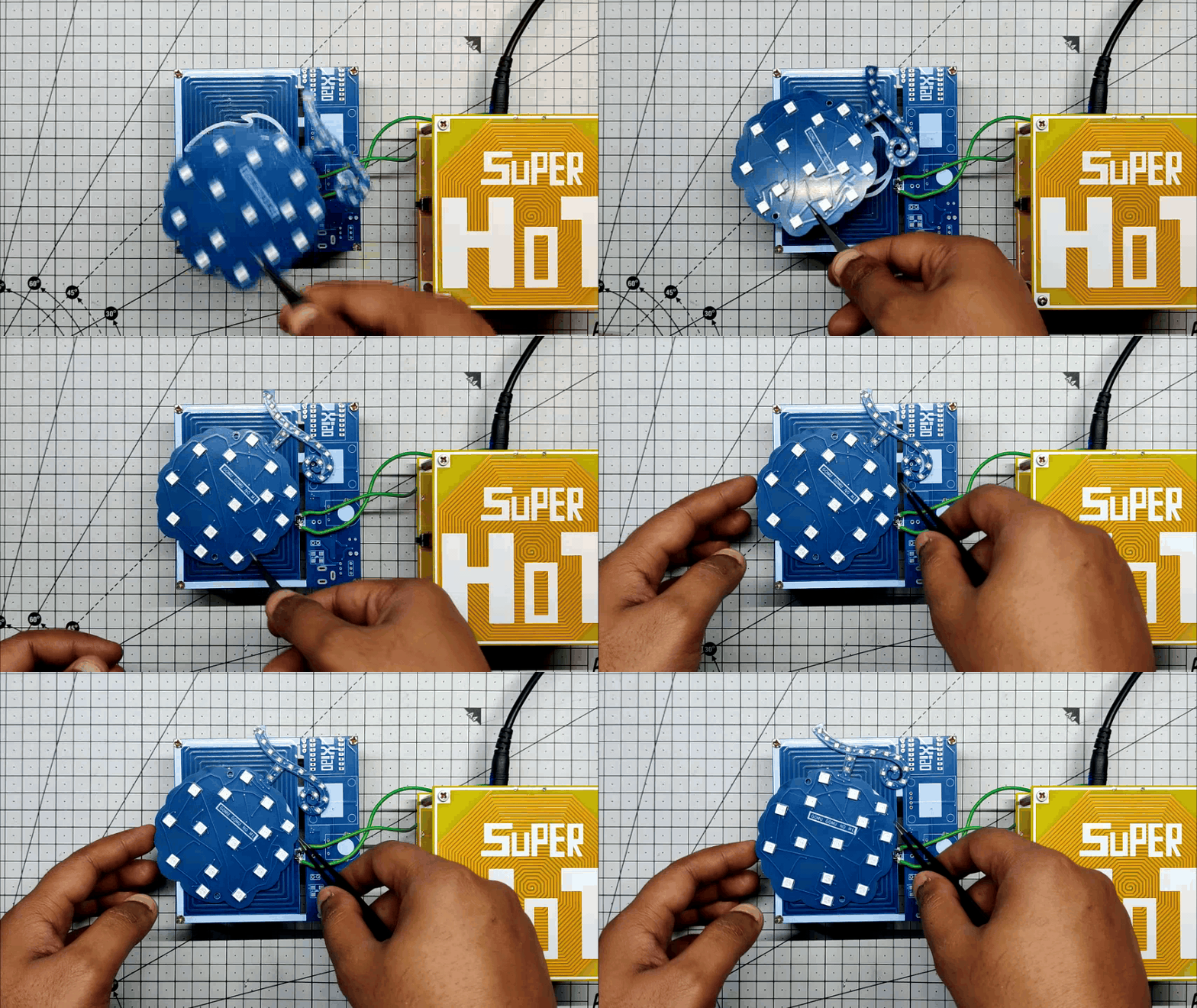
- Using a solder paste dispensing syringe, we first apply solder paste to each component pad individually to begin the PCB assembly process.
- Next, we pick and place each component in its location using an ESD tweezer.
- Following pick and place, we lift the PCB and place it on the reflow hotplate, which increases the temperature of the PCB from below to the point at which solder paste begins to melt and components are soldered to their pads.
- The board was then turned around, and solder paste was applied to the XIAO MCU's pads.
- Using a hot air reflow station, we heat the pads of XIAO in order to melt the solder paste and solder XIAO to PCB pads permanently.
PCB Assembly is now complete.
CODE
.gif)
.gif)
This is the project's simple source code, which is built on the Neopixel Library, which must be installed prior to uploading the Sketch.
Here's a breakdown of the code:
Include the Adafruit NeoPixel library:
#include <Adafruit_NeoPixel.h>
Define constants for the pins connected to the NeoPixel rings and the number of pixels in each ring:
#define PIN1 D0  // Connect to D0
#define PIN2 D1  // Connect to D1
#define NUMPIXELS1 15
#define NUMPIXELS2 15
Create two Adafruit_NeoPixel objects named pixels1 and pixels2 using the defined pin and pixel count. The line also specifies the color order (GRB) and the data rate (NEO_KHZ800):
Adafruit_NeoPixel pixels1 = Adafruit_NeoPixel(NUMPIXELS1, PIN1, NEO_GRB + NEO_KHZ800);
Adafruit_NeoPixel pixels2 = Adafruit_NeoPixel(NUMPIXELS2, PIN2, NEO_GRB + NEO_KHZ800);
Define global variables for timing delay and the RGB color components:
int delayval = 10; // Timing delay
int redColor = 0;
int greenColor = 0;
int blueColor = 0;
In the setup function, initialize both NeoPixel objects and show the initial state of the LEDs (all off):
void setup() {
  pixels1.begin();
  pixels2.begin();
  pixels1.show();
  pixels2.show();
}
In the loop function, continuously call two functions, ring1() and ring2(), which control the behavior of each NeoPixel ring with a delay of 500 milliseconds between the calls:
void loop() {
  ring1();
  ring2();
  delay(500);
}
The ring1 function is responsible for controlling the first NeoPixel ring. It calls setColor() to set random values for the red and blue components of the RGB color, then iterates through each pixel, setting its color, displaying it, and introducing a delay. When i reaches the number of pixels, it resets to zero to repeat the pattern:
void ring1() {
  // ... (setColor is called)
  for(int i=0; i<NUMPIXELS1; i++){
    // Set pixel color
    pixels1.setPixelColor(i, pixels1.Color(redColor, 0, blueColor));
    pixels1.show();
    delay(delayval);
    // Check for the end of the ring and reset
    if (i == NUMPIXELS1){
      i = 0;
      setColor();
    }
  }
}
The ring2 function is similar to ring1 but controls the second NeoPixel ring with a fixed green color (0, 255, 10). It also uses setColor() to change the red and blue components, and it resets the index and color when it reaches the end:
void ring2() {
  // ... (setColor is called)
  for(int i=0; i<NUMPIXELS2; i++){
    // Set pixel color
    pixels2.setPixelColor(i, pixels2.Color(0, 255, 10));
    pixels2.show();
    delay(delayval);
    // Check for the end of the ring and reset
    if (i == NUMPIXELS2){
      i = 0;
      setColor();
    }
  }
}
The setColor function is called by ring1 and ring2 to set random values for the red and blue color components:
void setColor(){
  redColor = random(0, 20);
  blueColor = random(0, 255);
}
In summary, this code controls two separate rings of NeoPixel LEDs with different colors and patterns. The ring1 and ring2 functions iterate through the LEDs, setting their colors and introducing a delay to create a visual effect. The setColor function randomizes the red and blue components of the colors. The code is intended for use with specific hardware and requires the Adafruit NeoPixel library to function correctly.
Downloads
Final Assembly
.gif)


- Using two M3 PCB standoffs and two M3 bolts, we begin the final assembly step and attach the PCB standoffs to the LED board.
- The TOP PCB is then placed on top of the bottom board, aligned with the mounting holes, and fastened together with two M3 bolts.
GUM GUM Fruit has been assembled.
Result
.gif)
.gif)
.gif)
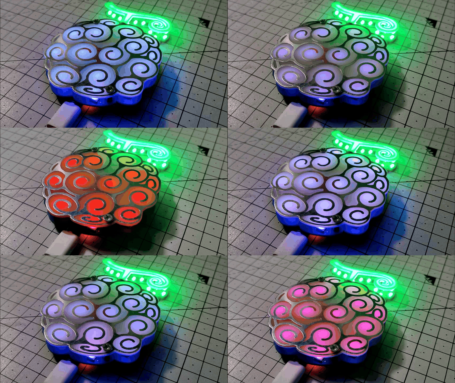
Here is the final result of this build: a PCB-based GOMU GOMU NO MI.
The Gum GUM fruit is purple in color; therefore, the code fluctuates between light purple and dark purple, but the stem's green color remains the same. The glow of the RGB LED can be seen from the top side, which looks fairly stunning.
A custom name plate or sign board is an example of how we can use this dual PCB sandwich technique to create engaging projects like this. The top board will have all the information and details, and the bottom board will contain the LEDs.
Ultimately, this project is finished, and more of these fruits will be created in the future, so stay tuned.
All the documents related to the project are attached. If you need any help regarding this project, DM me or leave a comment.
Special thanks to Seeed Fusion for providing PCBs for this project; do check them out if you need great PCB service for less cost.
Peace out, and I'll be back with a new project soon!