GIANT ESP8266


hello everyone,
please support our mission; igg.me/at/smartplants
today i would like to shine some light to a microcontroller that is changing the planet. a $3 wifi arduino that has leaped the DIY electronics world within the last few months. already at their 12+ version, ESP8266 is getting better everyday. it saddens me to see so many people are still unaware of this magical device. to get everyone's attention, and to help others make up their mind about getting one or not - i present to you the Giant ESP8266.
inspired by the infamous giant arduino and 555 timer footstool (thanks to the amazing authors - please click on their link)
.
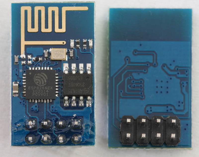
to keep everything classic, i decided to go with ESP8266-01 version (blue board). i remember when it first came out and how hard it was to work with, unstable powering issues, hard to program..
.
today ESP can be programmed using the regular Arduino IDE, just like any other arduino board itself. it comes with many different shields to be easily plug&play.
.
you will need,
1x powebank (optional to make it mobile)
0.5" thick wooden board
0.25" thick wooden board
dark blue, blue, black, silver and gold spray paint
.
let's get making..>
Research & Design & Cut


i found the highest resolution/quality ESP-01 image i could find on google images; http://www.martyncurrey.com/wp-content/uploads/201...
.
downloaded the picture to trace it with a vector drawing software, i used adobe illustrator
.
zooming in to get every little detail, i outlined all the parts..
.
i cut the parts using a local CNC machine. you can easily use hand tools to cut the parts, just be careful
.
or even better search for a local makerspace, become a member and make something AWESOME. . remember to sand everything nice and smooth :)
Downloads
Paint Job


time to get into some fun stuff finally.. painting.!!
.
always keep a picture of the esp close by, or even better have an actual esp chip with you while painting to use as reference for the correct colors.
.
we start with a 1st light coat of paint. eventually the darker base blue will be covered on top with lighter blue paint where all the circuit connection are.
Antenna


print the attached PDF file
.
using an xacto knife carefully cut out the antenna part
.
using double sided tape, secure the cut out over your main board and paint with gold color..
Downloads
Circuit Veins


a bit more painting..
again, i traced the circuit using a vector drawing software. printed to pdf to trace
you can just download the PDFs and trace cut the design.
Tiny Pins/legs


for the legs i decided to cut strips of thick paper. as they are easy to bend/shape and free
cut 8 strips of 0.25"x5"
cut 32 strips of 0.125"x3"
.
these are the circuit connectors for the two bigger black components on the ESP. i drew cutting lines and painted the paper silver from the back, NOT covering the cutting lines. unpainted side will be on the bottom, so no problem. this is to help you cut the legs evenly/straight..
Actual Hardware + Software


as i mentioned, it's not just a prop, its a fully working ESP8266 with smartphone control.!!
.
ESP has 2 on board LEDs. blue for wifi connectivity and red for power. we will be hiding neopixel rgb LEDs inside our wooden frame for a realistic look/feel..
.
to program the esp8266 we must first follow few one time only quick download/install steps. ask in comments if you are stuck.
.
install the little esp8266 UART programmer driver
install arduino software on laptop
install blynk library to arduino software
get arduino software ready for the esp8266
install blynk app on phone or tablet and get the app ready
- launch app and sign up
- create a new project, choose board esp8266, email yourself "auth token"
- add widget > zERGBA > merge > pin V2
- add widget > zERGBA > merge > pin V4
.
now we are ready to upload the code, copy it from below. make sure to change your wifi & app settings first (auth token email) - line 4 for blynk project auth token - line 32 for wifi name & password
now open arduino software on laptop go to tools > boards > scroll down to choose "generic esp8266"
go to tools > port > choose the correct port & hit upload, wait about a minute and upload should finish
- before upload make sure that your board is wired to be in "upload mode" after the upload is done
go back to phone app and start your blynk project. it should start responding to your app..
Putting It All Together


time for the final assembly
Conclusion

what a fun project this was.. the esp8266 community is ever growing on the internet, below are some useful links that will help you find all the answers you are looking for, also don't forget to ask in the comments.!!!
.
esp8266 on instructables; https://www.instructables.com/howto/esp8266/
esp8266 community; http://www.esp8266.com/
esp8266 wiki; https://en.wikipedia.org/wiki/ESP8266
blynk community; http://community.blynk.cc/
.
go ahead give it a try, you can automate ANYTHING with esp8266. can't wait to see your wild projects :)