GETTING STARTED WITH IoT With ESP8266 MicroController
by RobotsCraft in Circuits > Electronics
10963 Views, 136 Favorites, 0 Comments
GETTING STARTED WITH IoT With ESP8266 MicroController
This Tutorial gives a brief description of ESP8266 MicroController and Programming languages used to Program the Controller.
- For More Tutorials Follow
- To buy ESP MicroController and Other Interesting Stuff , Please visit http://robotscraft.com/
P.S - We are Open to Feedback. Your Feedback will help us to Make better Tutorials.
Regards,
Team RobotsCraft
Introduction to ESP8266 MicroController
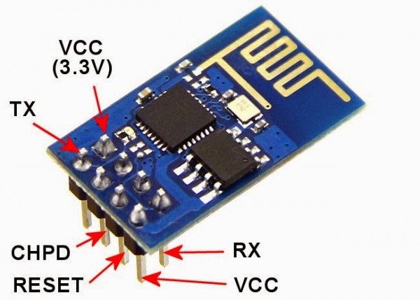
The ESP8266 is a microcontroller built by Espressif Systems that includes WiFi built in. Even though they are produced by same manufacturer there are different variants that are made by various vendors. ESP-01 and ESP-12E are one of the most important variant for ESP microcontroller series. The main different between the variants are the number of the gpio ports exposed for user. For example ESP-01 has eight pins that are user accessible while ESP-12E has 22 pins that are accessible
Specification of ESP8266 MicroController
The ESP8266 has the following specifications:
Property- Description
1) Voltage - 3.3 V (3.0 – 3.6 V tolerated)
2)Current 10 uA – 500 mA (64 mA average).
3)Processor Tensilica L106 32 bit
4)Processor Clock 80-160MHz
5)RAM 32K + 80K (explained below)
6)Storage Flash memory, 16MB max (512 K – 4 MB often provided)
7)GPIOs 17 (multiplexed with other functions)
8)ADC 1 (10 bit) WiFi 802.11 support b/g/n/d/e/i/k/r
9)TCP Connections Max: 5 concurrent
Programming Methods for ESP8266 MicroController
Methods for programming ESP8266
There are a variety of methods to program the ESP8266 including:
- AT (terminal) commands
- Official ESP8266 SDK and Toolchain
- NodeMCU with eLua
- Arduino IDE
Description of these languages are given in Steps Below.
AT Commands
The first programming method we want to discuss is using AT commands. This method uses the ESP8266’s dedicated UART (serial communication) pins to communicate with and program the microcontrollers. Compared to the other programming methods discussed below, this technique is arcane, but worth mentioning if you need to do some (very) low-level debugging.
The ESP8266 has three pins for (3.3 volt) serial communications. There are two TX pins and one RX pin. In order to interface your computer with these pins, you will need to purchase a 3.3 volt serial adapter. More than likely you would want to get a USB module similar to the FTDI TTL-232R-3V3 for this task. The TX pins are used by the ESP8266 to transmit (send) data and the RX pin is used to receive data. Typically breakout boards arrange the pins such that one of the TX pins and one RX pin are located close to each other. These pins are often multiplexed as the GPIO13 and GPIO15 pins on the board. In most of the cases people often use these pins as GPIO as serial is not a high priority. The remaining TX pin is multiplexed with GPIO2.
ESP8266 SDK and Toolchain
The ESP8266 SDK is an IoT application development platform developed by Expressif (the manufacturers of the ESP8266 chip) that includes basic platform and high-level application development examples. It is sometimes called the “IoT SDK” in the forums. This SDK comes in two variants called the “Non-OS SDK” and “RTOS SDK”. Both of these are low-level, C SDKs that are partially open-source. Both have specialized timers and other functionality that let you save power and maximize the performance of the device.
The “Non-OS SDK” forces developers to use timers and callbacks to write software. Although this programming setup is very power efficient, most folks complain that it introduces so many layers of abstraction that it is difficult for most people to follow the program flow. Also, this approach requires that you build your software around the espconn network interface and its usage rules which appear to be too restrictive for most developers to tolerate. The “RTOS SDK” is based on FreeRTOS (an open-source project whose code is hosted on GitHub). The RTOS SDK provides a full multi-tasking operating system which uses “typical” methods of programming to implement desired functionality. If you want to get the most performance out of the hardware, this is probably the method you want, but keep in mind that the code you generate will be tied very tightly to the underlying platform and thus will not be highly portable to other projects or platforms.
ELua and NodeMCU
An open-source firmware and development kit that helps you to prototype your IOT product within a few Lua script lines. Open-source, Interactive, Programmable, Low cost, Simple, Smart, WI-FI enabled.
The firmware uses the Lua scripting language. It is based on the eLua project, and built on the Espressif Non-OS SDK for ESP8266.
Arduino
One of the most popular platforms for IoT devices out needs almost no introduction: the Arduino. Given my previous experience with my Arduino from OddWires, learning the ESP8266 can be programmed using this technique was much welcomed. This technique gives you access to most (but not all) of the libraries found in the Arduino IDE as well as a very well understood development process for IoT devices.
Our future tutorial will be based on ESP-12E and majorly ESP-12E based nodemcu development board.
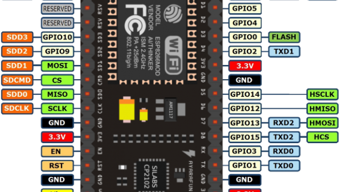
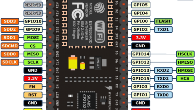
Pin Map for ESP-12E Board
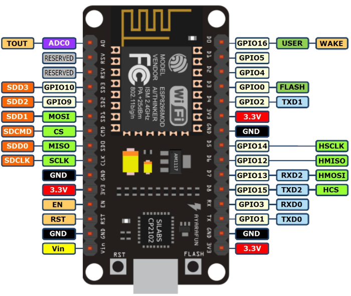
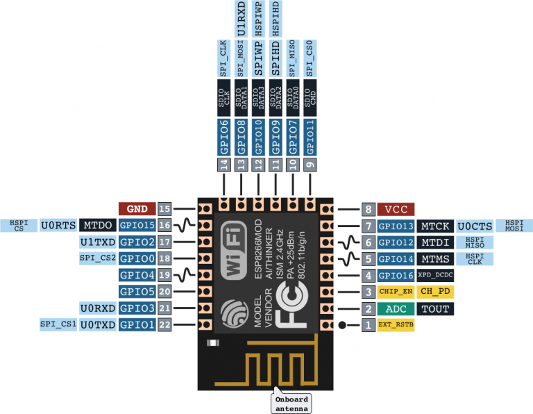
Above Images Show the Pin Map for ESP-12E Board
NodeMcu Development Board:
An open-source firmware and development kit that helps you to prototype your IOT product within a few Lua script lines. Open-source, Interactive, Programmable, Low cost, Simple, Smart, WI-FI enabled
Features
- NodeMCU is the fast leading edge low cost technology to WiFi.
- Modern high level mature LUA based technology. It is an integrated unit with all available resources on board. It is super simple to complement your existing Arduino projects or any development board that has I/O pins available.
- Modern Internet development tools such as Node.js can take advantage the NodeMCU with the built-in API to put your idea on the fast track immediately.
- NodeMCU is built based on the mature ESP8266 technology to take advantage the abundant resources available on the web.
- NodeMCU has ESP-12 based serial WiFi integrated on board to provide GPIO, PWM, ADC, I2C and 1-WIRE resources at your finger tips, built-in USB-TTL serial.
Getting Started
Before you use the micro USB cable to connect the ESP8266 NodeMCU with your computer, you need to install the cp2012 USB driver
After successful connections you need to download software’s such as lualoader and lua Editor. The luaEditor is used to programming and debugging, finally it will generate .lua file. The LuaLoader is used to download and compile the .lua file, and it provides some other features.
How to Use Lua Loader? Step-1
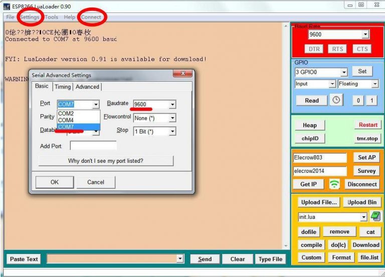
*Open the LuaLoader, click the menu “Setting”, choose the “Comm port Settings”, and it will popup a “Serial Advance Setting”, set up the right port here then click the “Connect” button on the top of the menu.
When the information “Connected to COMX at 9600baud” is displayed on the debug window, it means connection is successful, and you can input command statement into the below edit box. (Follow in Step-2 of How to Use Lua Loader)
How to Use Lua Loader? Step-2
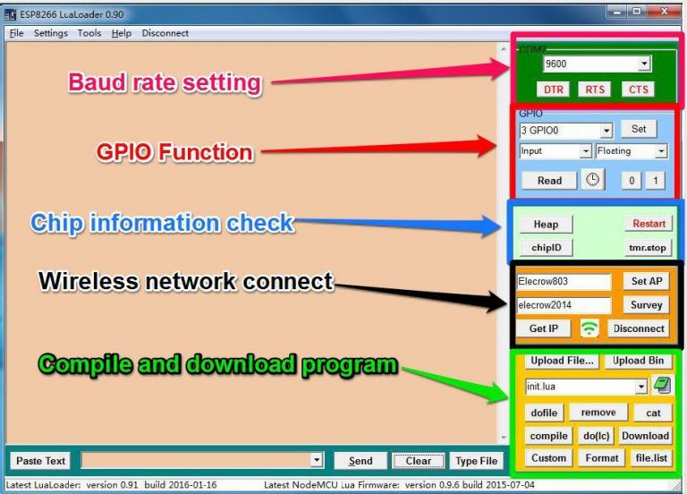
When the information “Connected to COMX at 9600baud” is displayed on the debug window, it means connection is successful, and you can input command statement into the edit box shown in the image
Also, you can use some of the function which display on the right side of Lualoader interface.
- Baud rate setting: set the baud rate that you need , normally set at 9600.GPIO
- Function: Choose different GPIO port, set its mode(Input, Output or Interrupt ),set GPIO Pull up resistor (Floating, Pull up or Pull down), and “Read” or “Write” operation to the GPIO port
- Chip Information: Check the information about the chip or restart the NodeMCU.
- Wireless network connect: Enter the wireless network account and password, you can connect it and get the IP.
- Compile and download program: First, click “Upload File…”upload the .lua file that you want to download. Secondly click “compile” to compile the .lua file, through the compile can click “Download” to download the program.
Other Useful Resources and Links
For More Tutorials Follow
- For Buying of ESP8266 MicroController,RaspberryPI,Arduino and other Accessories , Please Visit
Regards,
Team RobotsCraft