Fytt Io

This project was done by Josh Elias Joy and Aniket Chandekar as part of our Masters in Product Design and Management Course at IIIT Hyderabad.
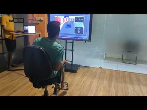
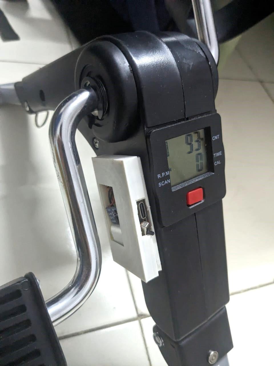
Inspired by the prop cycling arcade games, we wanted to make a modern rendition of the same along with fitness stats. Modularity was a primary design consideration as we wanted the hardware to be setup with existing cycles.
Also unlike a regular prop cycle arcade game we wanted to steer using the upper body movement, this is done by using computer vision.
Supplies
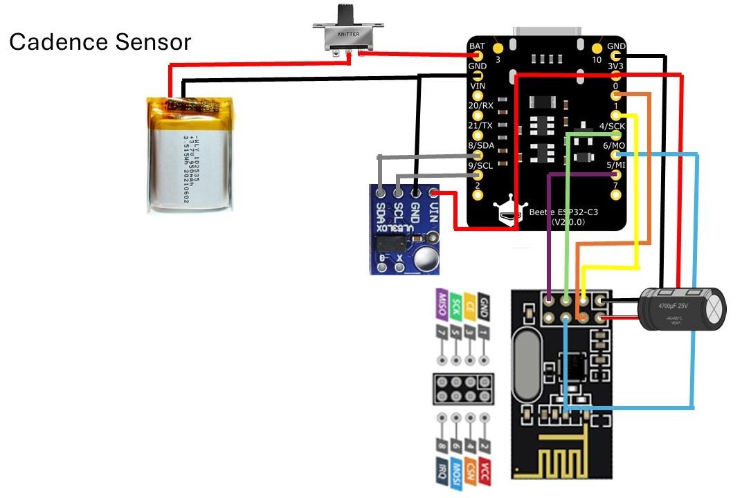
Cadence Sensor
1) DFrobot ESP32-C3 Bettle
2) NRF24L01
3) VL53L0X Time of Flight Ranging Sensor
4) 400 mAh battery
5) Slide Switch
6) Capacitor
Receiver
1) Raspberry PI Pico
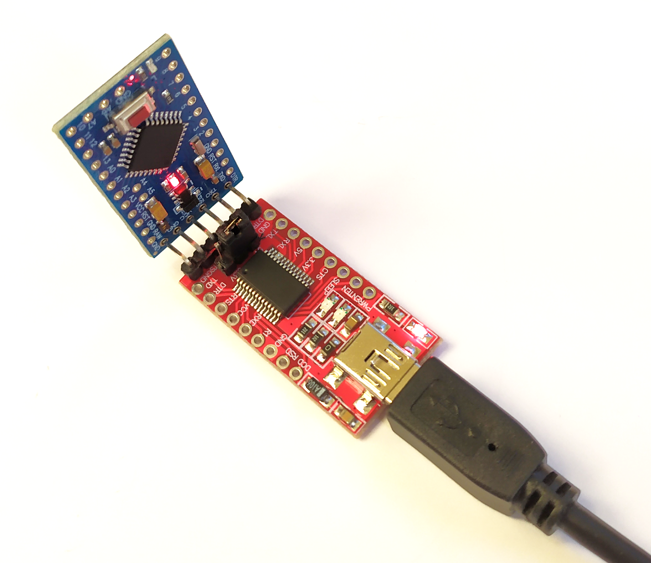
2) Arduino Pro Mini
3) NRF24L01
Tools
1) Soldering Iron
2) Wire
Others
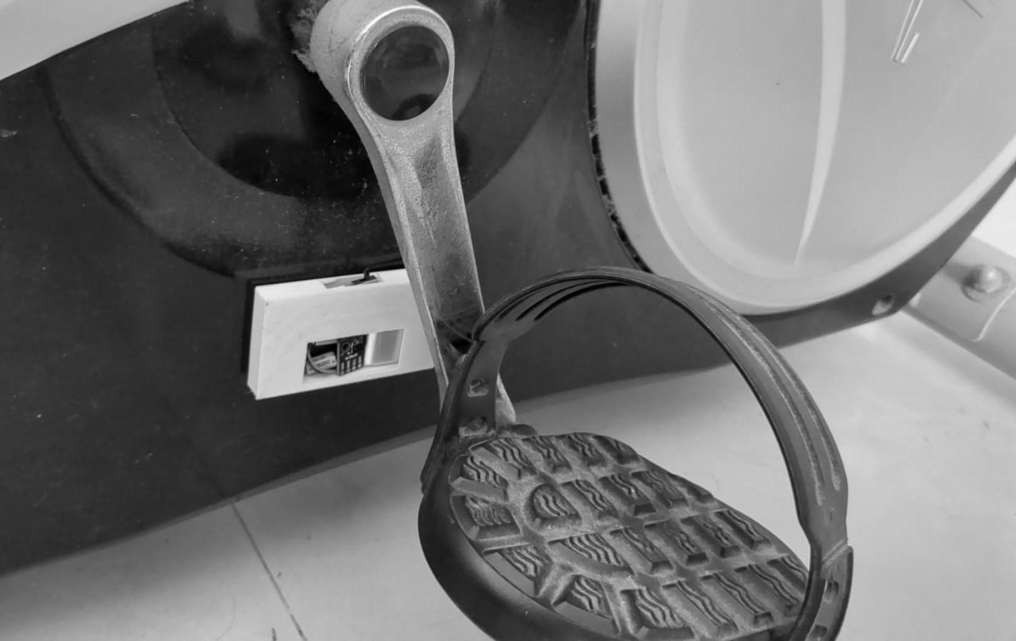
1) An Exercise Bike
Building the Circuit
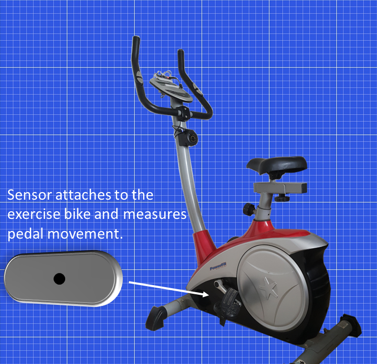
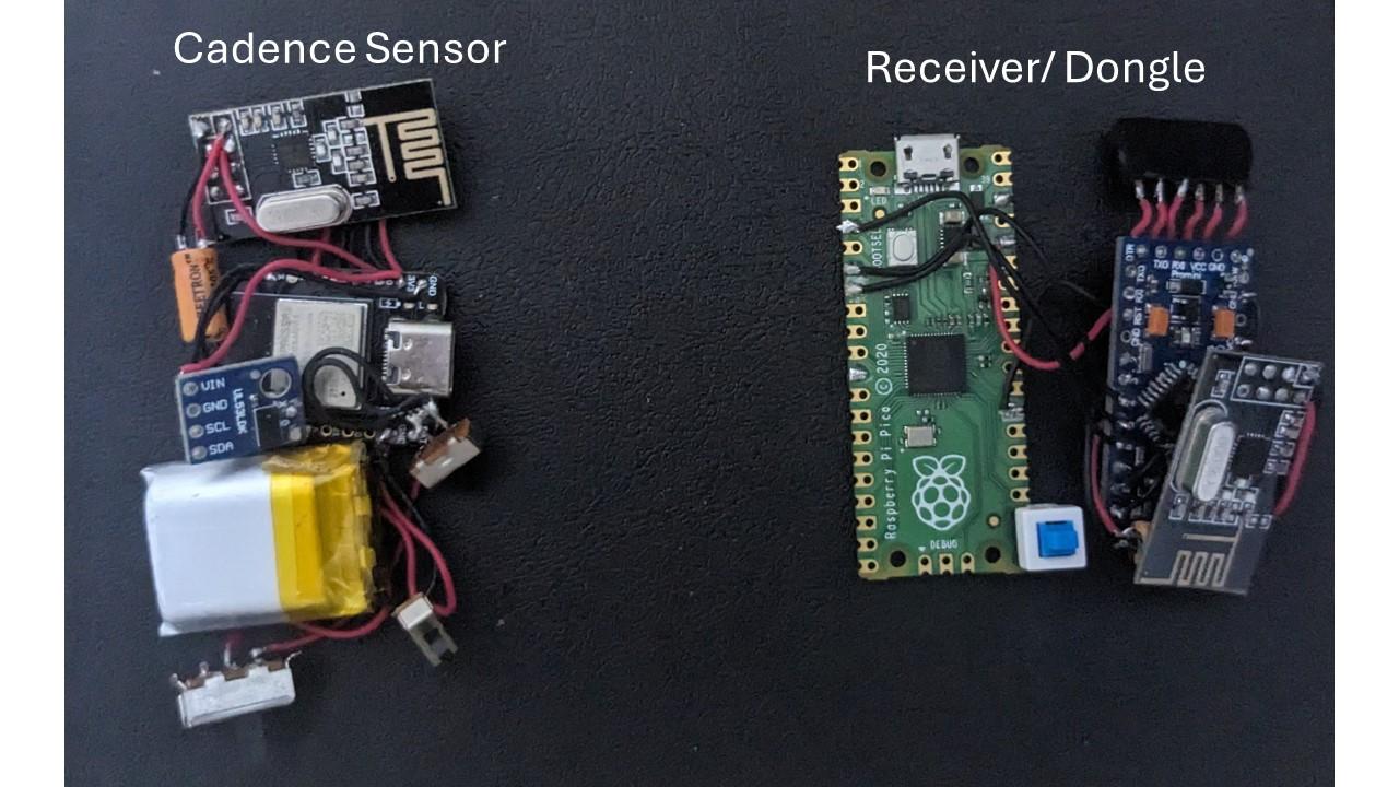
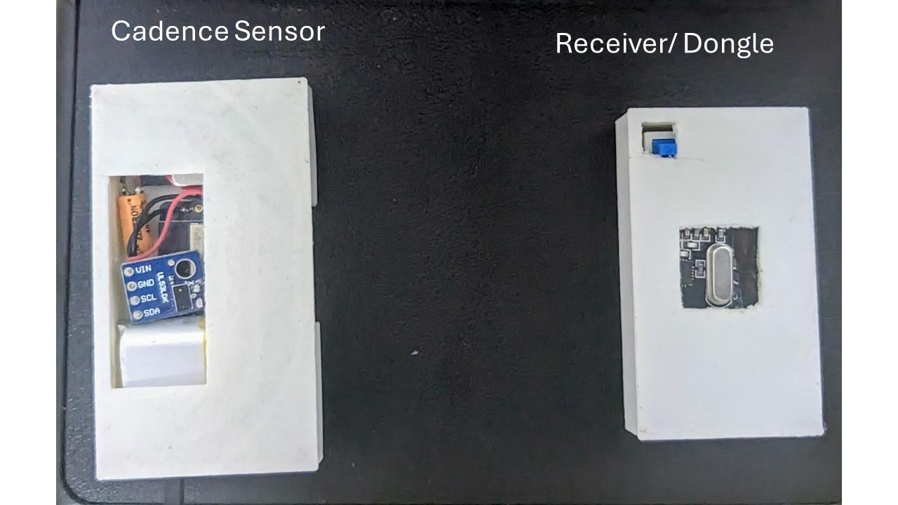
The System consists of a cadence sensor and dongle / receiver.
The Cadence Sensor Consists of:
DFrobot ESP32 C3 Bettle, has an inbuilt lipo charging circuitry and is in a compact form factor.
Nrf24l01, The nrf24lo1 is a cheap, robust, and low-power wireless transceiver.
VL53L0X Time of Flight Ranging Sensor
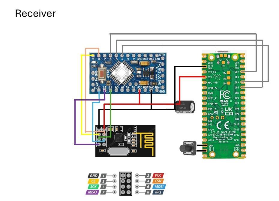
The Dongle Consists of
Raspberry Pi Pico, can emulate a keyboard, mouse or xbox 360 controller.
Nrf24l01, The nrf24lo1 is a cheap, robust, and low-power wireless transceiver.
Arduino Pro Mini, The pro mini and nrf24l01 is used to turn the Raspberry Pi pico into a wireless gamepad.
Building an Enclosure With Fusion 360
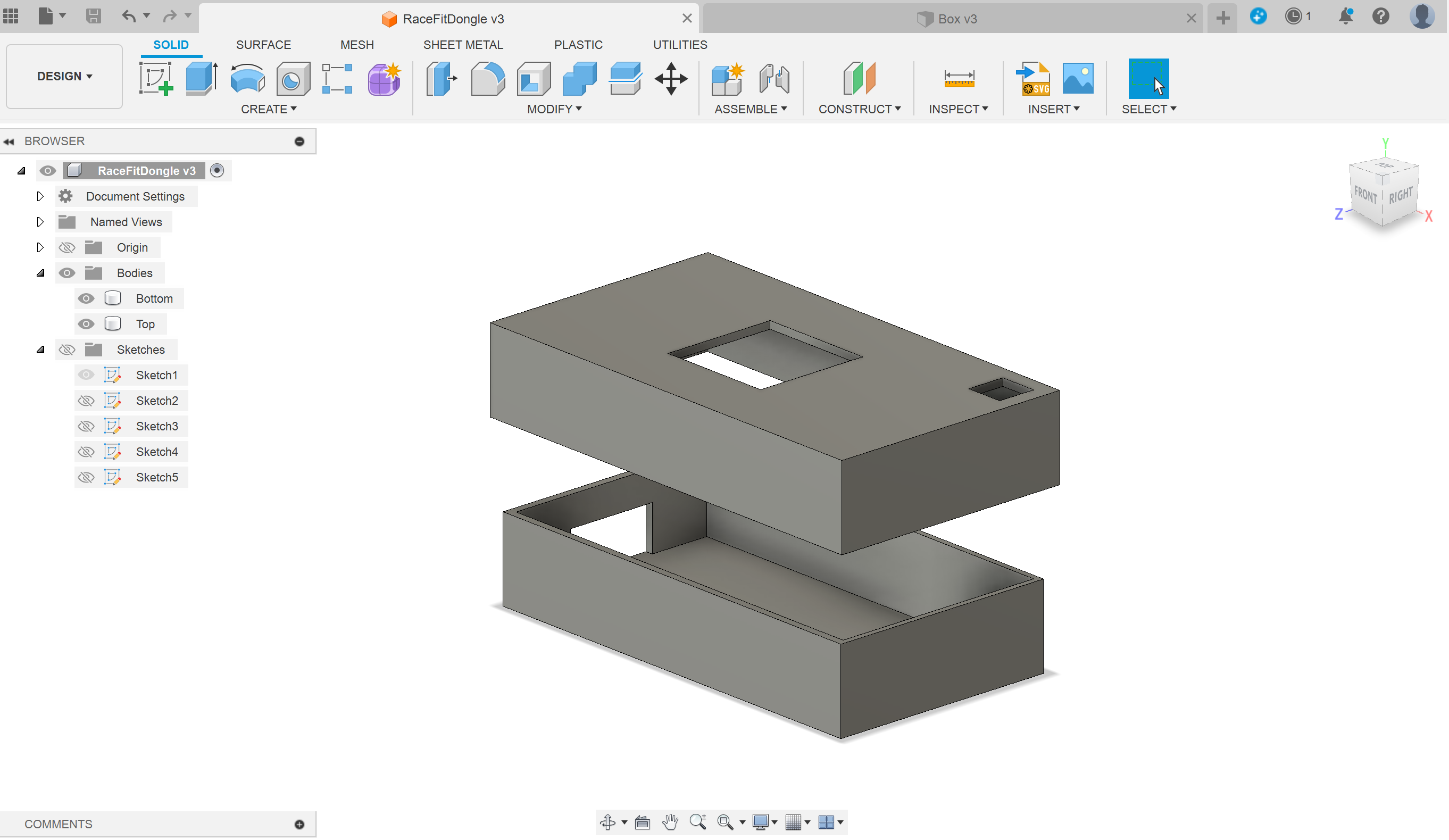
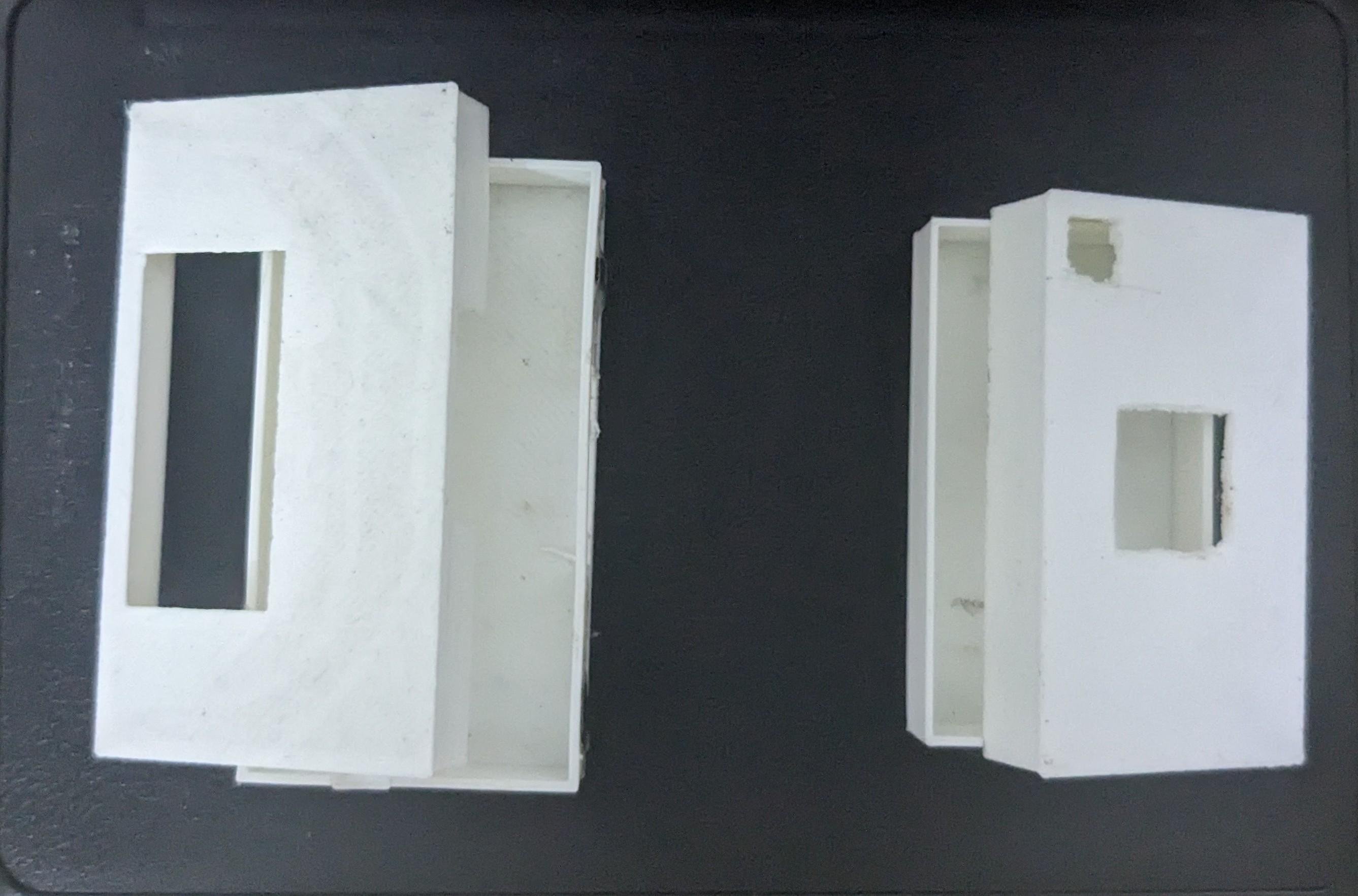
Designing an enclosure for the Cadence Sensor
1. Create a new design and sketch the base
- Open Fusion 360 and start a new design.
- Click on ‘Sketch’ in the toolbar and select the ‘XY’ plane as your sketching plane.
- Use the ‘Rectangle’ tool to draw a rectangle on the ‘XY’ plane. The dimensions of the rectangle will determine the base length and width of your box.
2. Extrude the base
- Once you’ve finished sketching the rectangle, click on ‘Create’ in the toolbar and select ‘Extrude’.
- In the ‘Extrude’ menu, enter the desired extrusion distance which will be the height of your box. Click ‘OK’ to complete the extrusion.
3. Add a sketch for the top face
- Click on ‘Sketch’ again in the toolbar.
- This time, select the top face of the box you just extruded as your sketching plane.
4. Sketch the cutout lid
- Depending on the design you want for the lid, you have two options:
- Rectangle with cutout sections for hinges: Sketch a rectangle that covers the entire top face of the box. Then sketch rectangles on the top face to represent the areas that will be cut out for the hinges.
- Separate lid: Sketch a rectangle that is slightly smaller than the top face of the box. This will create a separate lid for the box.
- Whichever option you choose, use the ‘Extrude’ function to cut out the lid. In the ‘Extrude’ menu, set the ‘Type’ to ‘Cut’ and enter a value that will cut all the way through the box.
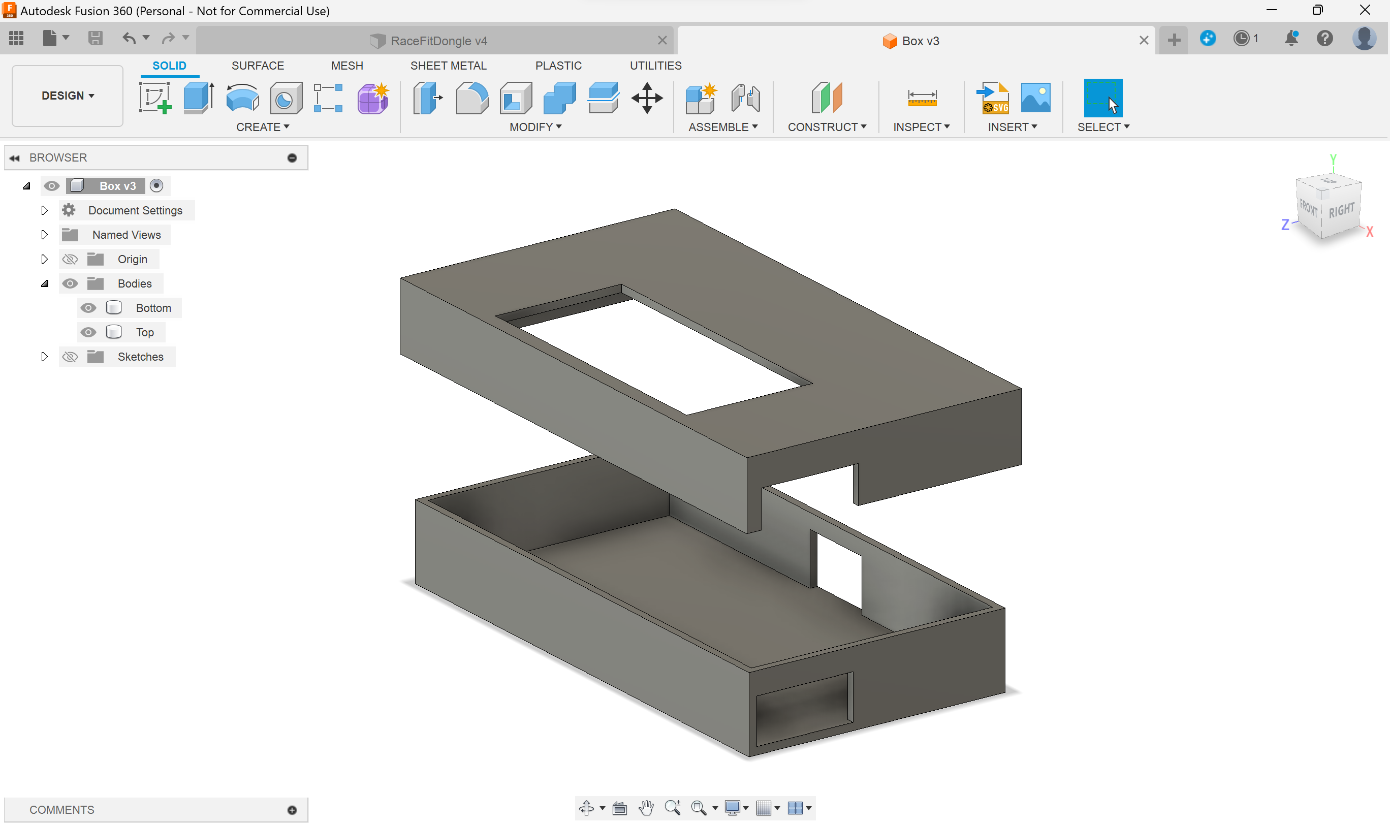
Designing an enclosure for the Dongle
1. Create a new design and sketch the base
- Open Fusion 360 and start a new design.
- Click on ‘Sketch’ in the toolbar and select the ‘XY’ plane as your sketching plane.
- Use the ‘Rectangle’ tool to draw a rectangle on the ‘XY’ plane. The dimensions of the rectangle will determine the base length and width of your box.
2. Extrude the base
- Once you’ve finished sketching the rectangle, click on ‘Create’ in the toolbar and select ‘Extrude’.
- In the ‘Extrude’ menu, enter the desired extrusion distance which will be the height of your box. Click ‘OK’ to complete the extrusion.
3. Add a sketch for the front face
- Click on ‘Sketch’ again in the toolbar.
- This time, select the front face of the box you just extruded as your sketching plane.
4. Sketch the cutout for the lid
- Sketch a rectangle on the front face that matches the width of the base. The height of the rectangle will determine the depth of the lid.
- Use the ‘Extrude’ function to cut out the lid. In the ‘Extrude’ menu, set the ‘Type’ to ‘Cut’ and enter a value that will cut all the way through the front face.
5. Add a new body for the lid
- Click on ‘Create’ and select ‘Solid’ from the dropdown menu.
- Select ‘Box’ from the sub-menu.
- Sketch a rectangle on the ‘XY’ plane that matches the dimensions of the lid cutout you created in step 4.
- Extrude the rectangle to the desired height of the lid.
6. Position the lid
- Click on the ‘Move’ tool in the toolbar.
- Click on the lid and hover over the box until you see the blue highlight. This will allow you to position the lid precisely.
- Use the arrows or enter the desired values to position the lid where you want it in relation to the box.
Uploading Firmware
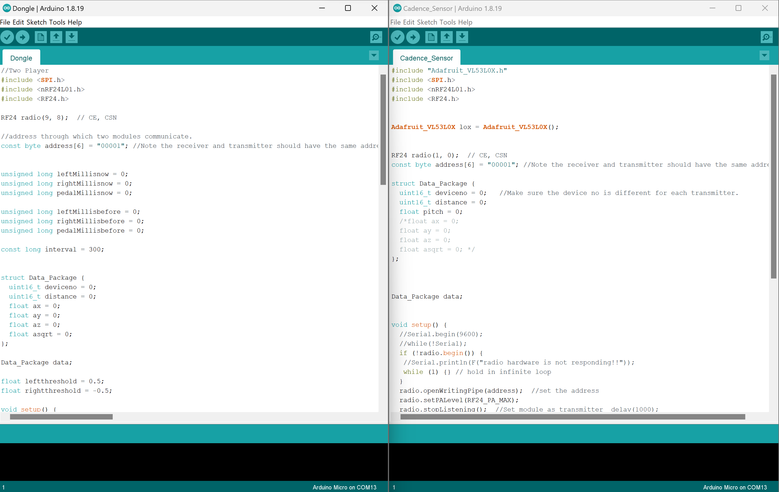
The Arduino IDE has been used to Programme the devices. Here is a getting started guide, note that I have used the Legacy IDE.
The Following Library have been used, to easily communicate with nrf24:
To turn the Raspberry Pi Pico into a Gamepad the GP2040-CE Multi Gamepad Firmware is used: https://gp2040-ce.info/
The Cadence sensor code communicates with VL53L0X Time of Flight Ranging Sensor to compute the distance, the nrf24l01 transceiver module is used to wirelessly transmit the distance reading to the dongle.
The Dongle Code toggles digital pin 6 when the distance becomes less than 3.5 cm thus a pedal is detected. Pin6 of the Arduino pro mini is attached to the Pi pico.
Building the Game
We followed this course to build the game in Unity: https://www.udemy.com/course/kart-racing/?utm_source=adwords&utm_medium=udemyads&utm_campaign=Unity_v.PROF_la.EN_cc.INDIA_ti.8154&utm_content=deal4584&utm_term=_._ag_83171830254_._ad_533157661084_._kw__._de_m_._dm__._pl__._ti_dsa-774930034729_._li_9062136_._pd__._&matchtype=&gad_source=1&gbraid=0AAAAADROdO2GIJTiR-FLutOpnGz4bQoFD&gclid=CjwKCAjw17qvBhBrEiwA1rU9w9rWbh0t8M-SBqGkfvrtyub4R5LVGMgyVDVYUNCVKmaejmuuMvGn_BoC3l4QAvD_BwE
Developing the Fyytio game in Unity involves several steps. Here's a general outline of the process:
Conceptualization and Planning:
● Define the game concept: Determine the type of racing game, the style, and any unique features you want to include. ● Plan the game mechanics: Outline how the cars will handle, the types of races, power-ups, and other gameplay elements.
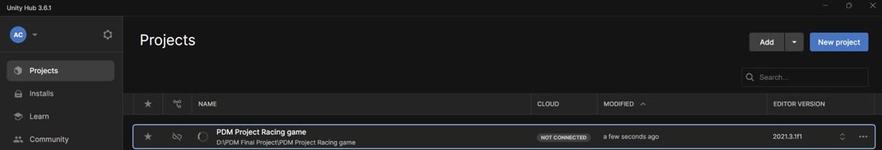
Set Up Unity:
● Install Unity Hub and the Unity Editor.
● Create a new Unity project and set project settings.
Assets and Resources:
● Acquire or create 3D models for cars, tracks, and other elements.
● Obtain or create textures, sounds, and other necessary assets.
● Organize assets in the project folders.
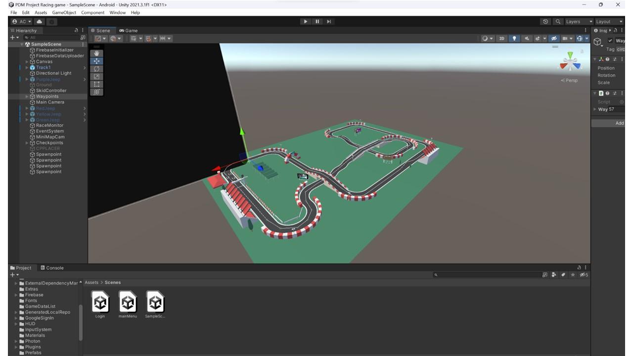
Scene Design:
● Design the race tracks using Unity's scene editor.
● Place checkpoints, starting lines, and other important elements.
● Set up the terrain, environment, and any obstacles.
Physics and Car Controls:
● Implement realistic car physics or stylized physics based on the game's design.
● Set up controls for the player's car, including acceleration, braking, steering, and drifting.
Camera System:
● Set up a camera system that follows the player's car.
● Implement features like smooth camera transitions and dynamic camera angles.
Gameplay Mechanics:
● Implement race logic, lap counting, and scoring systems.
● Integrate power-ups, boosts, or other special abilities.
● Handle collisions, crashes, and penalties.
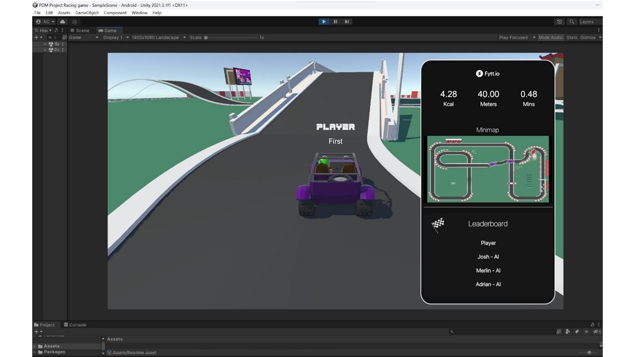
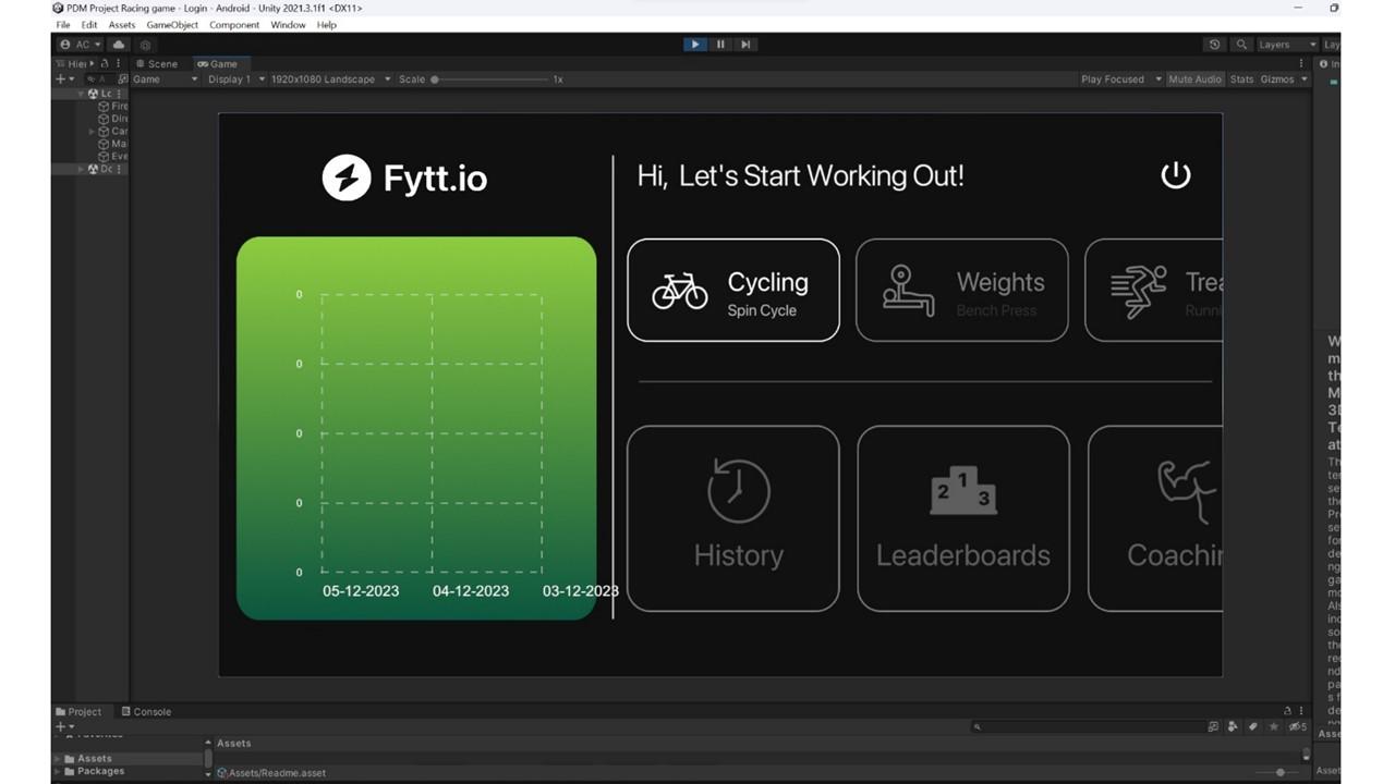
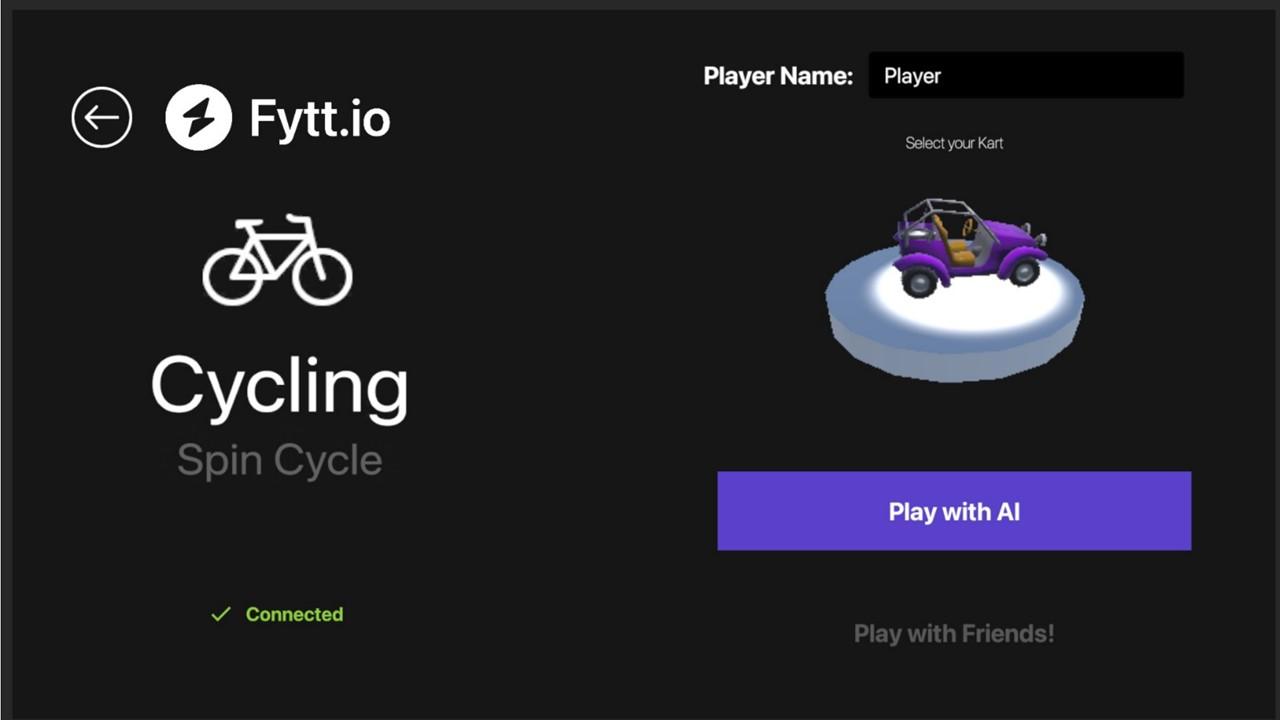
User Interface (UI):
● Design and implement the game's UI, including the HUD, lap counters, and score displays.
● Add menus for starting races, selecting cars, and adjusting settings.
Audio:
● Integrate engine sounds, background music, and other audio effects.
● Implement sound triggers for events like drifting, collisions, and power-up usage.
Testing and Iteration:
● Playtest the game regularly to identify bugs and improve gameplay.
● Gather feedback from testers and make necessary adjustments.
● Optimize performance for smooth gameplay.
Computer Vision Based Steering
The Following libraries have been used:
OpenCV: https://pypi.org/project/opencv-python/
CVZone: https://pypi.org/project/cvzone/
Mediapipe: https://pypi.org/project/mediapipe/
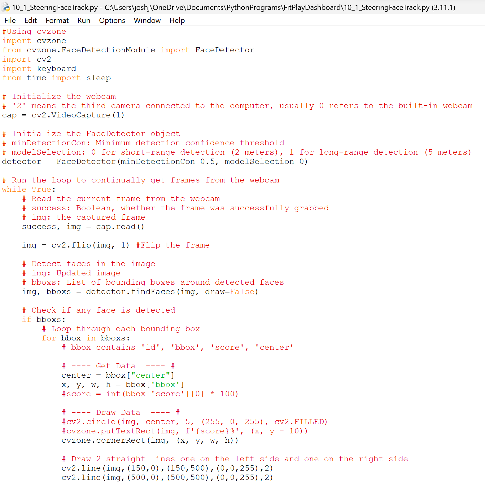
Python Libraries like Open CV, MediaPipe, CVzone, and keyboard were used for computer vision and provide appropriate keystrokes to steer the vehicle.
If the face is on the left part of the screen then the left arrow key is pressed and if the face is on the right part of the screen then the right arrow key is pressed,
Downloads
Building a Dashboard (Optional)
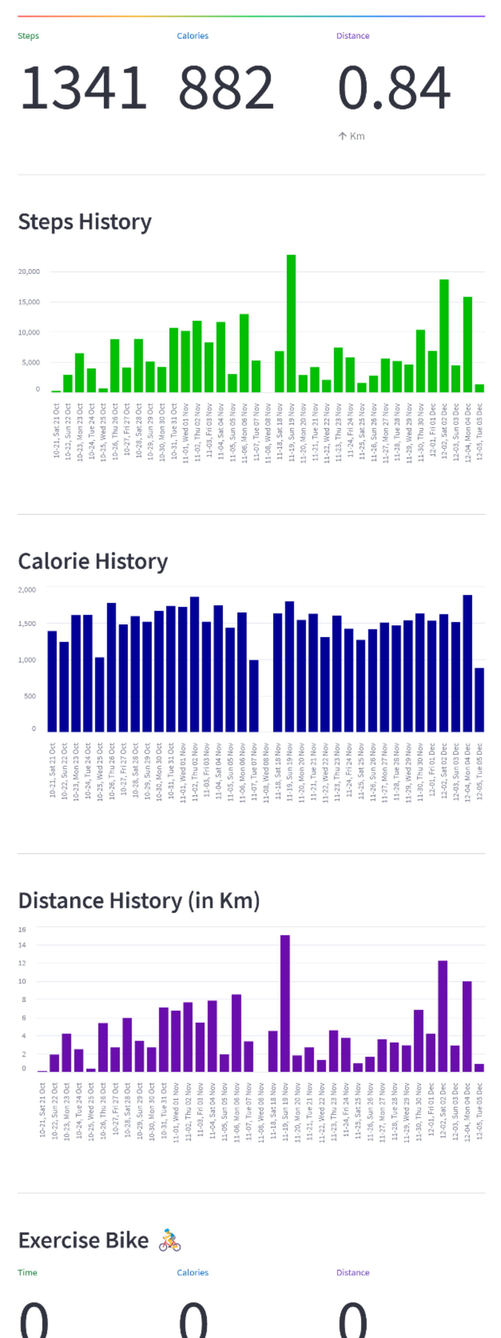
The Send to database code reads your google fit data by calling the google fit API and stores the fitness data in a firebase database.
The Read from database code reads data from firebase and displays the data in a streamlit dashboard.
The Dashboard was built using Streamlit library: https://streamlit.io/
Steps to get Google fit API credentials
Prerequisites:
- A Google Cloud project with the Google Fit API enabled (https://cloud.google.com/)
- A Python environment with the required libraries:
- google-auth-oauthlib
- google-auth-httplib2
- googleapiclient.discovery
- You can install them using pip:
- Bash
pip install google-auth-oauthlib google-auth-httplib2 googleapiclient.discovery
- Use code with caution.
- content_copy
Steps:
- Enable the Google Fit API:
- Go to the Google Cloud Console (https://cloud.google.com/) and select your project.
- Navigate to "APIs & Services" -> "Library."
- Search for "Google Fit API" and enable it.
- Create OAuth 2.0 Credentials:
- Go to "APIs & Services" -> "Credentials" and create credentials.
- Choose "OAuth client ID" and select "Desktop app" as the application type.
- Download the JSON credentials file (e.g., credentials.json).
Guide on creating a Firebase Realtime Database and using it in Python:
1. Create a Firebase Project:
- Head to the Firebase console (https://console.firebase.google.com/).
- Click "Add project" and give it a descriptive name.
- Enable Google Analytics (optional) and click "Create project."
2. Enable Realtime Database:
- In the left sidebar, navigate to "Realtime Database."
- Click "Create database" and select a region closest to your users.
- Choose "Test mode" for development (allows read/write for 30 days).
- Click "Done" to create the database.
3. Install the Pyrebase Library:
- Open your terminal or command prompt.
- Use pip to install the library:Bash
pip install pyrebase
- Use code with caution.
- content_copy
4. Obtain Firebase Configuration:
- In the Firebase console project overview, click the gear icon for "Project settings."
- Go to "General" -> "Your apps."
- Click "Add app" and choose "Web."
- Register the app (name doesn't matter much).
- Under "Configuration," copy the entire contents of the firebaseConfig variable. This includes API key, project ID, etc.