Fusion 360 Proportional Design for the Violin
by bassman76jazz in Workshop > CNC
3758 Views, 5 Favorites, 0 Comments
Fusion 360 Proportional Design for the Violin
This is the technique I use to design string Instruments in Fusion 360. I first learned about this system from a series of videos made by Kevin Kelly . I have adapted his "Four Circle" system to be used with the constraints in fusion 360. This system has a few key advantages
- The created drawings are compromised of the least possible arcs to form an outline or profile.
- Due to the proportional relationship the shapes they form are very pleasing to the eye.
- If these forms are are to be CNC cut the resulting g-code for the machine will be greatly simplified and the cuts will be very smooth.
-The drawings will be easier to scale by simply modifying a single dimension (with some limits)
-The base form will be very easy to work with for making other jigs and fixtures in the instrument building process.
I will demonstrate this process using a violin body shape but this technique can be used to draw the base form of any instrument or contour. In this example I will draw the outline of the Guarneri 'del Gesu' "Vieuxtemps" violin from 1741. It is clear to me that this process was used in one form or another by the masters that designed these great instruments.
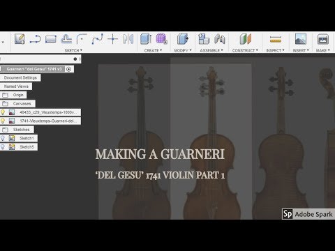
If you find the wording in this tutorial too confusing I have embedded a video and screen-cast of the processes I use in Fusion360 . In the next few weeks I will be following up this tutorial with the process for drawing sound holes, scrolls and complete modeling and construction a replica of this instrument. If your interested in following along on this process please subscribe to my YouTube channel.
Attach a Canvas
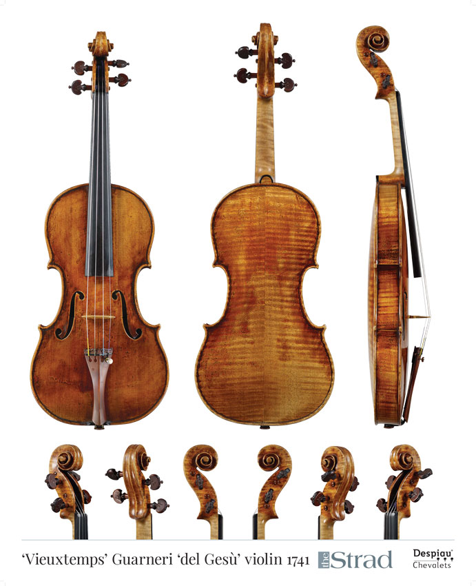
First attach a canvas to the XY plain in Fusion360.(this is my preference you can work on any plane or create a offset or plain from angle to work from) Once your image is in fusion calibrate the attached canvas to the desired dimensions. When choosing an image to work from it is best to find or make an image with as little optical distortion as possible,The closer to a true profile the better. It will be very difficult to get good results from an image not taken directly in line of the profile of the instrument. I usually calibrate a few time as I get closer to the actual dimension each time.
Primary Circle
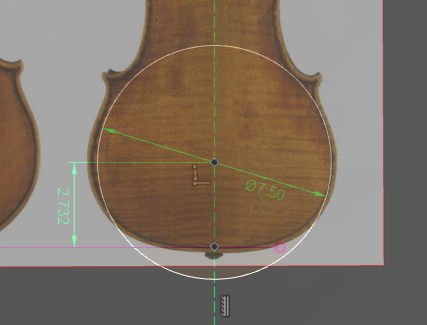
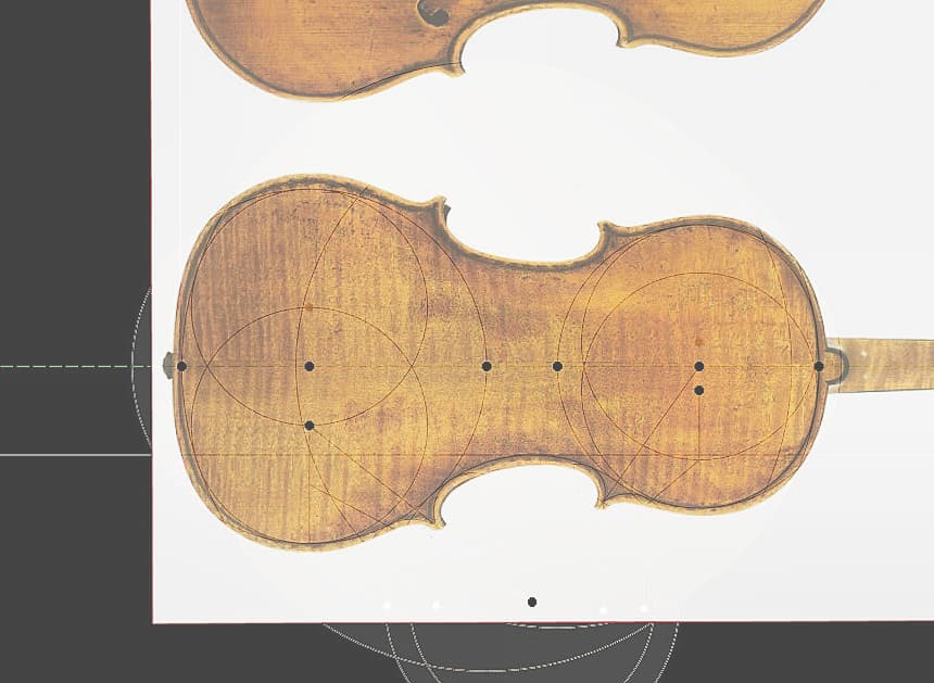
I usually use the widest part of the lower bout to create the primary circle. Dimension this circle and make sure it is full constrained. This is the dimension that will determine all other circles in the drawing. In this example I will be concentrating on making the proportional circles match as closely as possible to the right half of this image as there is a little distortion on the left side and ultimately they instrument is symmetric.
I usually try to get as close as possible to the image in the attached canvas and then round to a number that is somewhat normal. So if the first dimension is 7.123456789 I would round it up to 7.125, if this is to large I might step it down to 7.12 or 7.11.
The nice part about using Fusion360 to make these drawings is that you can define the dimension by formula. when you create a circle and add a dimension to it you can modify this dimension by reference to another dimension and multiply, divide , add, and subtract from it as well. Fusion360 will do all the hard work of determining the exact dimension.
Vesica Piscis
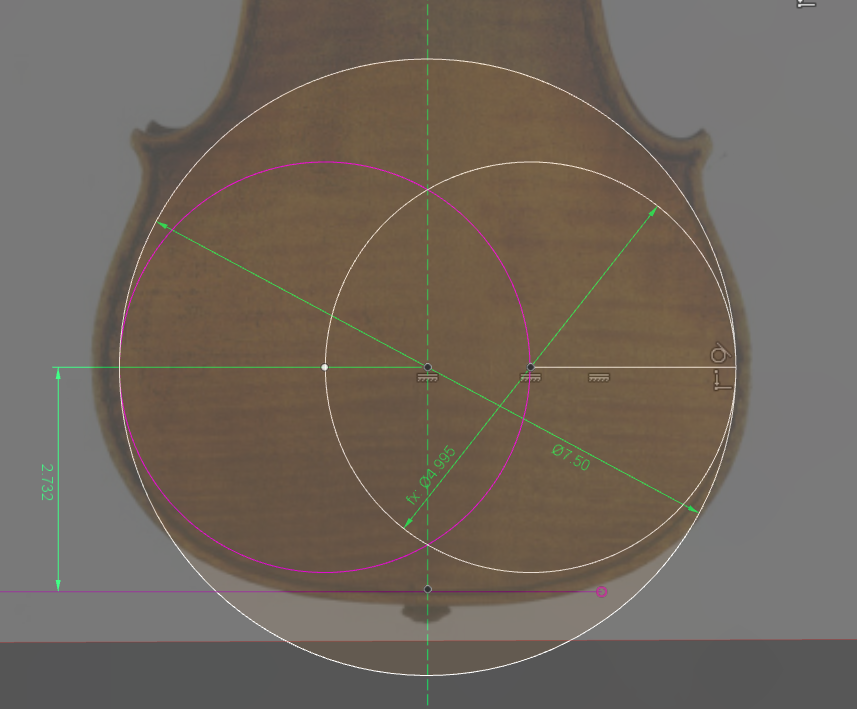
The "Vesica Piscis" or "Fish badder" is a shape used in design and mathematics that is formed by two overlapping discs. For our purposes some proportion of the lower and upper bouts defined this shape. We will make ours proportional to the primary circle that we just defined.
https://en.wikipedia.org/wiki/Vesica_piscis
The proportions of all of the other elements can be any division or multiplication of the primary circle or circles derived from it, however there a few classical proportions that seem to make designs that are particularity pleasing to the eye.
The Square Root of 2 https://en.wikipedia.org/wiki/Square_root_of_2 or roughly 1.412
the Golden Section https://en.wikipedia.org/wiki/Golden_ratio or roughly 1.618
2/3 or roughly .666
4/5 or .8
5/6 or roughly .833
In this example the two discs that make up the lower Vesica Piscis will be 2/3 or .666 of the lower bout circle and constrained horizontally to the primary circles center point and also tangent to the primary circle (ya, I know that's a mouthful)
C-bout and Upper Bout
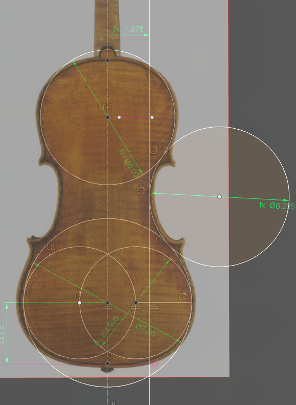
To form the C-bout we will have to draw and constrain the the other circles that define the shape.
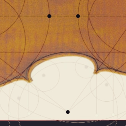
The upper bout circle will be .8 (4/5) of the lower bout and the C-bout will be .833 (5/6) of the lower bout. To constrain these circle I first offset a line from the center line of the instrument to 1/4 of the lower bouts diameter. The C-bout circle will be constrained by a tangent to the lower primary circle and the offset center line. the upper bout circles center point will be constrained vertically to the lower bout center and by tangent to the C-bout circle. Again a Vesica Piscis will be drawn in the upper bout circle at .83 (5/6) of the upper bout. From this point we can draw the top and bottom arcs of the instrument. these are drawn form the point where the upper and lower bout circles meet the center line to the lower and upper tangent of the two Vesica Piscis.
Point Lines and Corner Circles
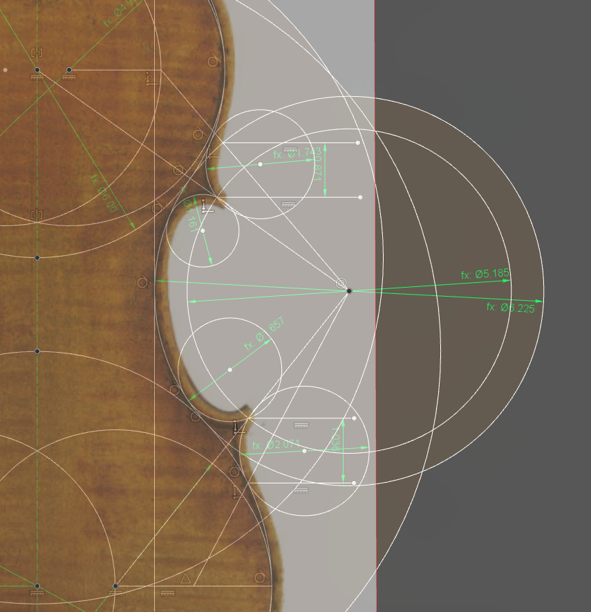
In order to draw the circles that form the points where the C-bout and Upper and Lower bouts meet lines are drawn from the center point of the C-bout to
-The upper bout center point and to a point where the Vesica Piscis and the center of the upper bout meet
-On the lower bout at a point where the center point of the lower bout and the Vesica Piscis meet and half way between this point and the primary circles edge.
(I realize this is confusing if you can come up with a better way to articulate this I would be happy to make changes, otherwise the video and screen cast should help)
we will also need another circle drawn from the C-bout center at .833 (4/5) of the C-bout circle. were this circle and the center point lines meet will define the points.
I then draw lines from where the point lines meet the inner and outer C-bout circle and dimension between them. this dimension multiplied by 2 will make the circle between the upper bout circle and the point line, and the lower bout circle and the lower point line. The inside upper circle is proportional the the upper circle at .666 (2/3) and lower inside circle at .8 (4/5).
these circle are constrained by the upper and lower bout by tangent (or in the case of the inner circle the C-bout) and are coincident to the center point lines.
Modification of Proportions and Clean Up
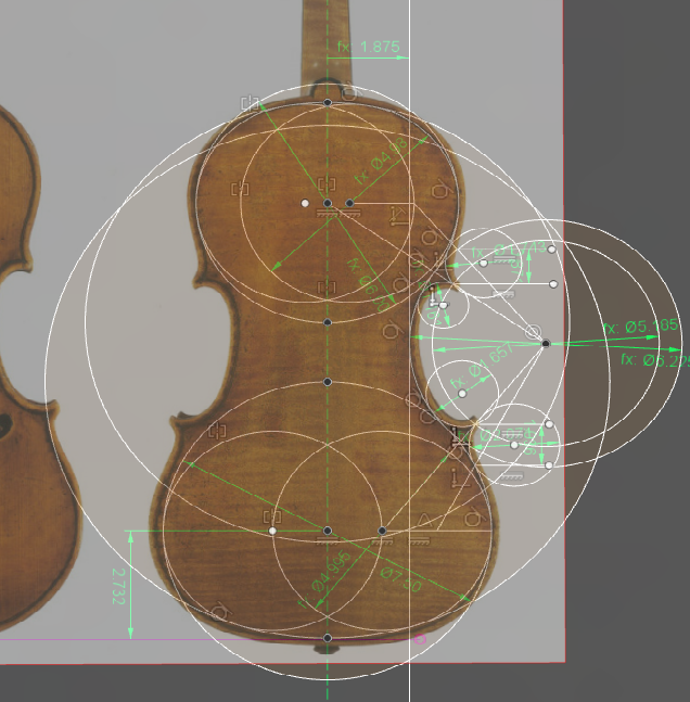
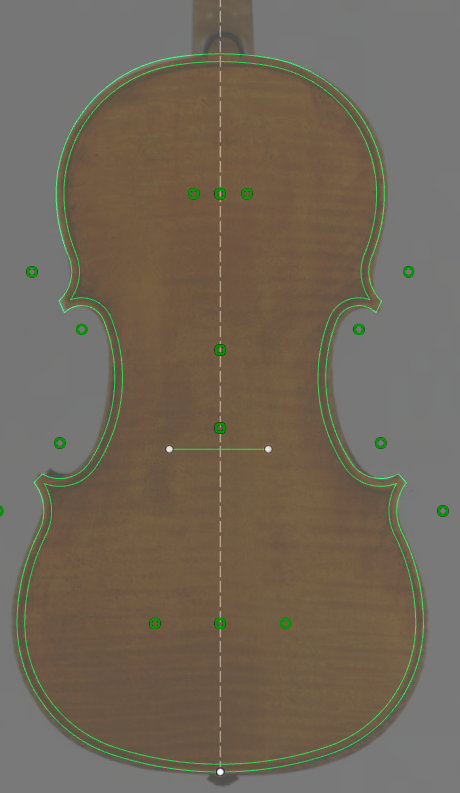
At this point any of the dimensions or proportions can be altered to suite your design needs. The primary circle dimension will scale the entire instrument to a degree. Finally I clean up all of the extra lines and mirror one half across the center line to the other side to complete the outline. This process can be modified to re-create almost any outline and the results are very pleasing to the eye, and easy on the CNC. Again I apologize for the complexity of the wording in this tutorial this was the best that I could do with this complex subject. please watch the video and the screen-cast for a better understanding of what I am doing.
Thanks,