Fusion 360 Claw Machine
by CSP-Austin in Design > Digital Graphics
688 Views, 1 Favorites, 0 Comments
Fusion 360 Claw Machine
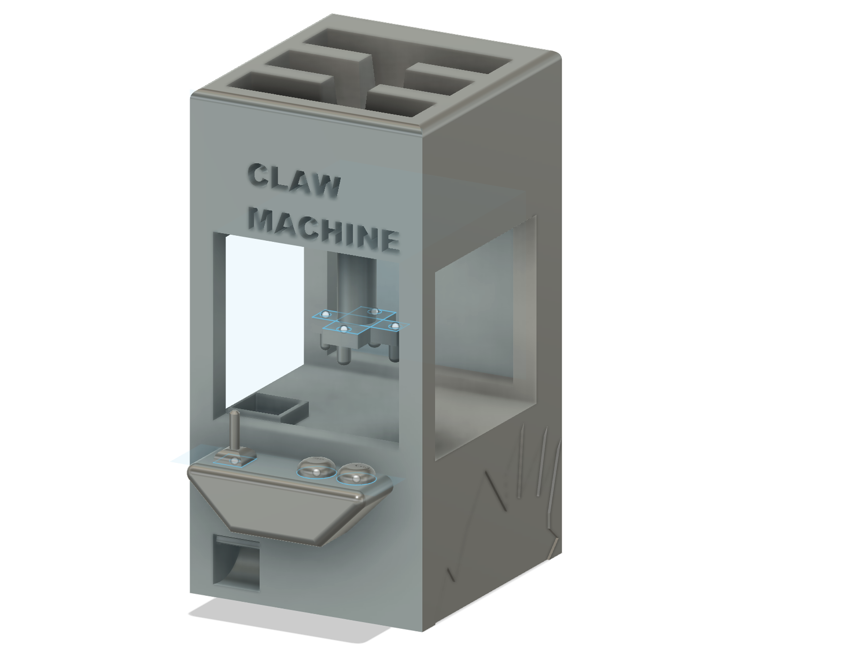
This is a claw machine model that represents what an average Claw Machine would look lie.
Supplies
All that is required for this project is Autodesk Fusion 360
Exstrude Shape
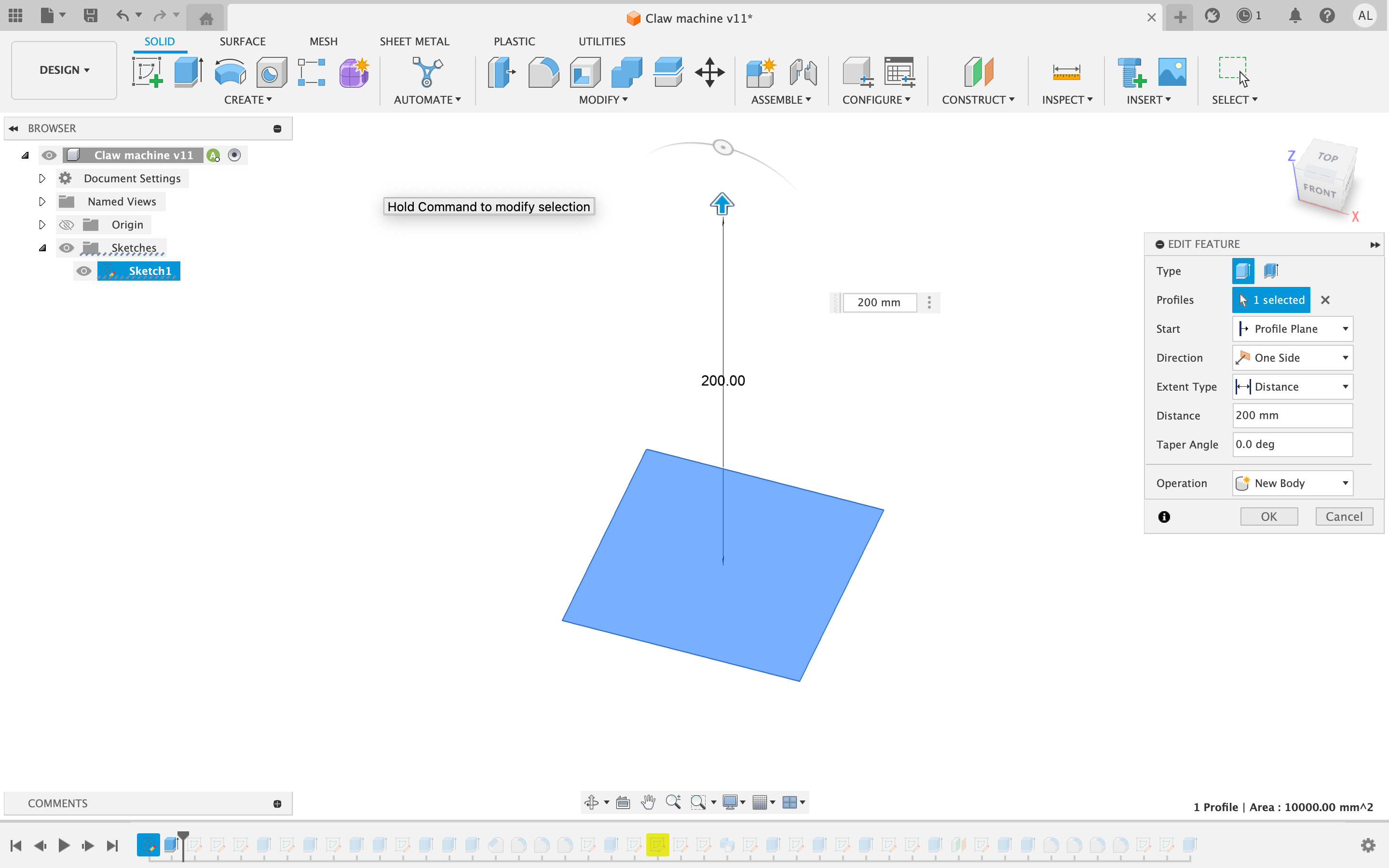
For the first step make a square 100 by 100 mm and extrude it 200mm up. Make sure you build on the base plane.
Creating the Inside
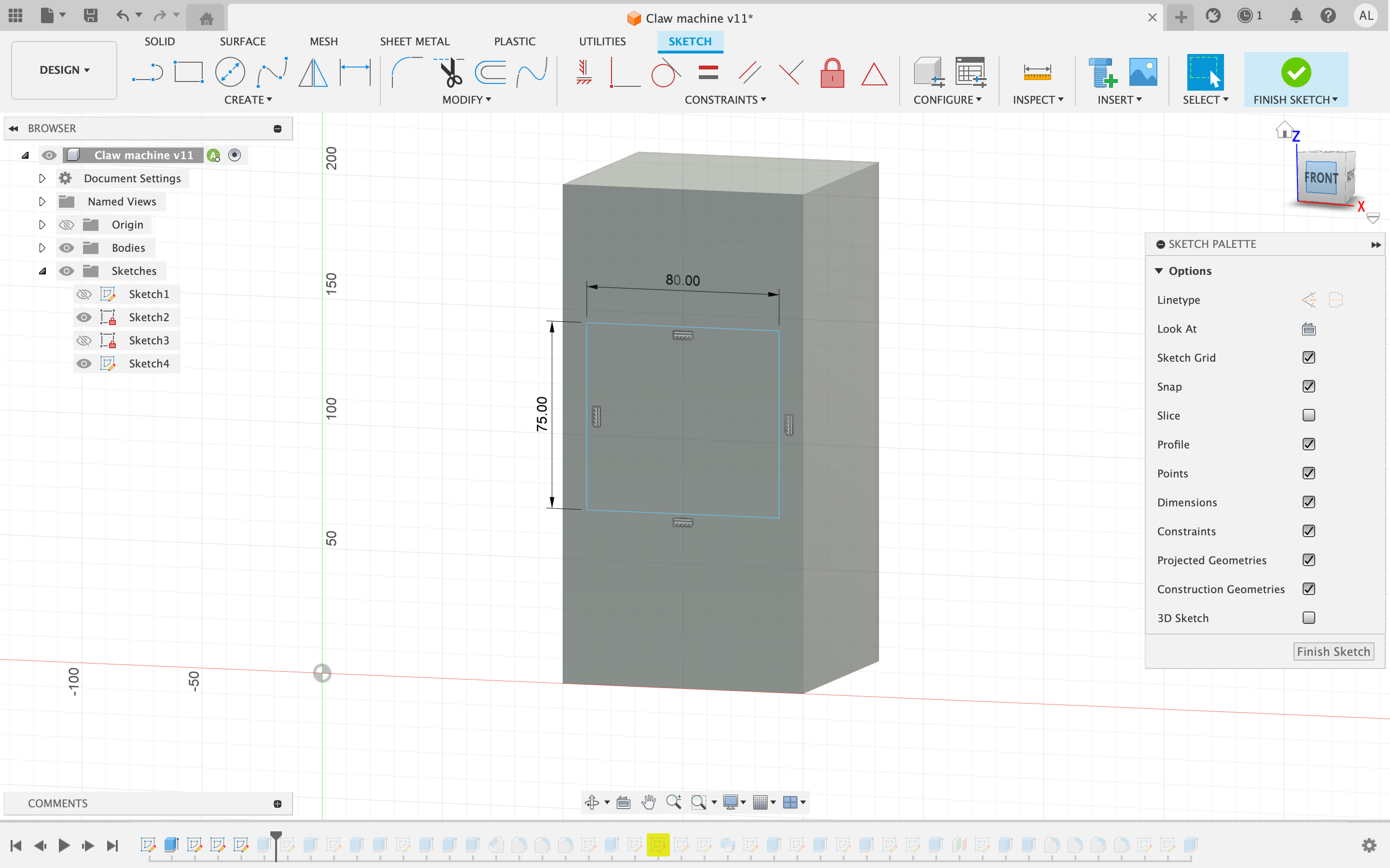
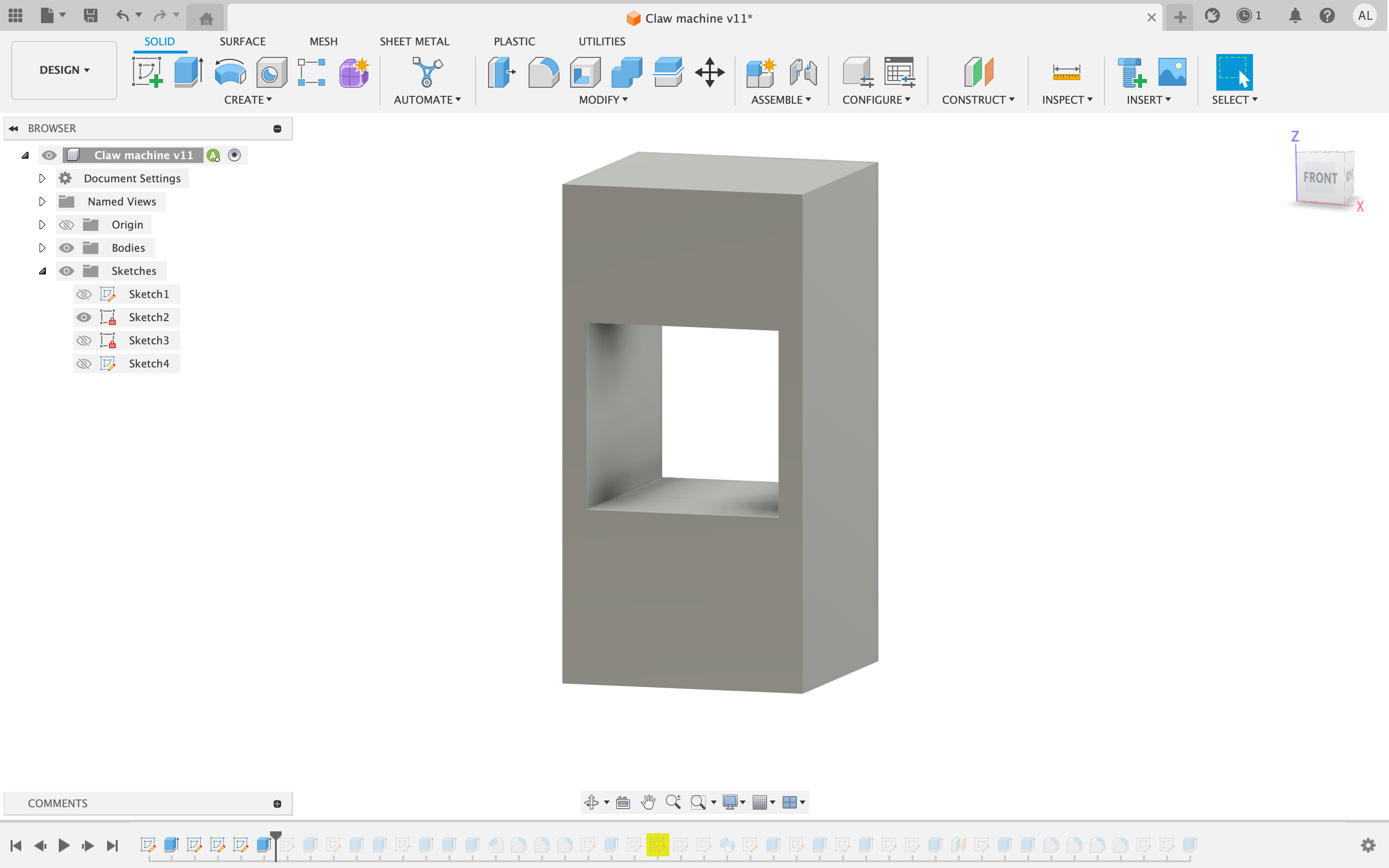
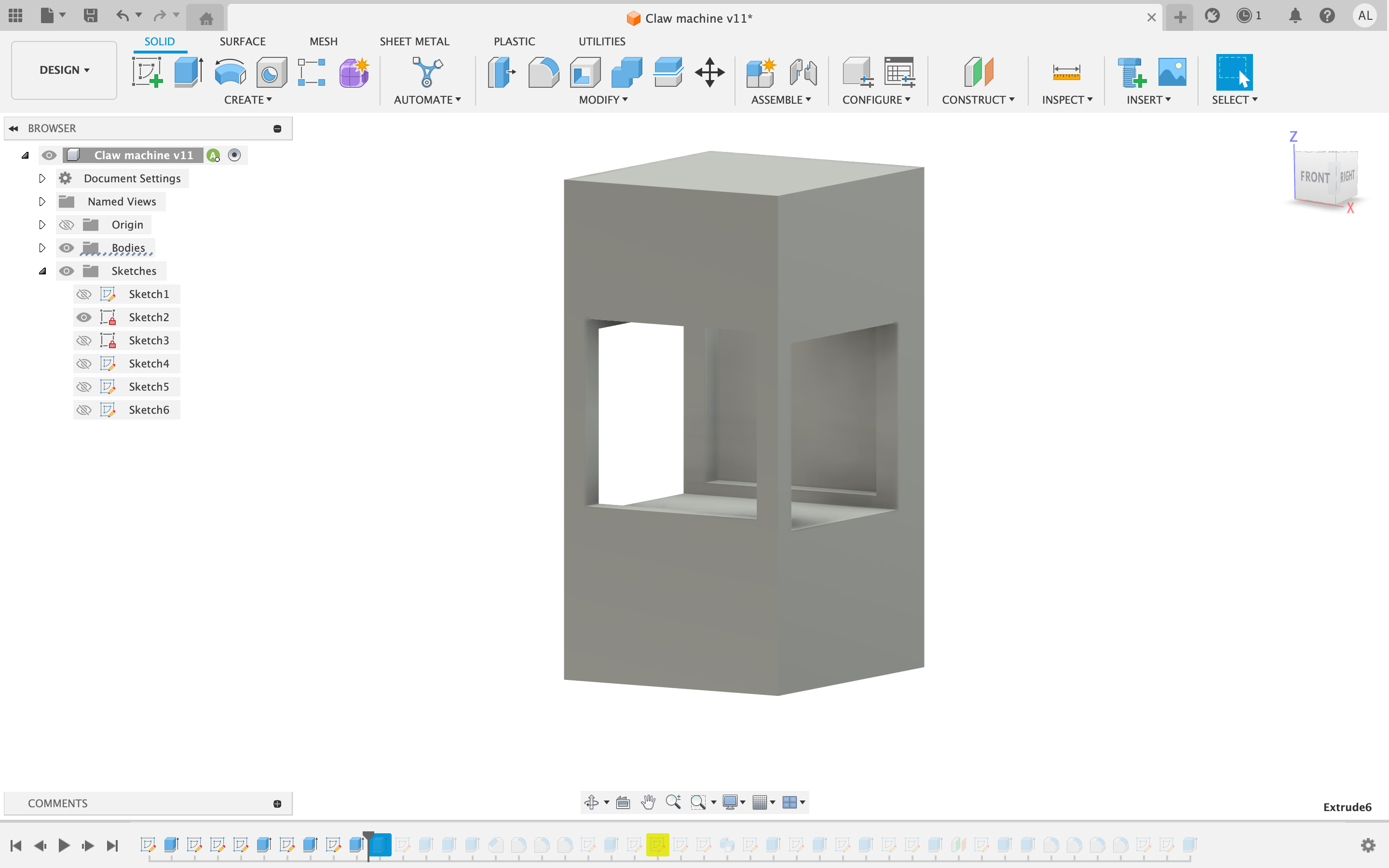
Once you have the rectangular shape create a rectangle 75 by 80mm in the center and cut through the entire shape. Repeat on the left or right face. Then extrude the back so that there are only three complete wholes.
Construct and Extrude the Self
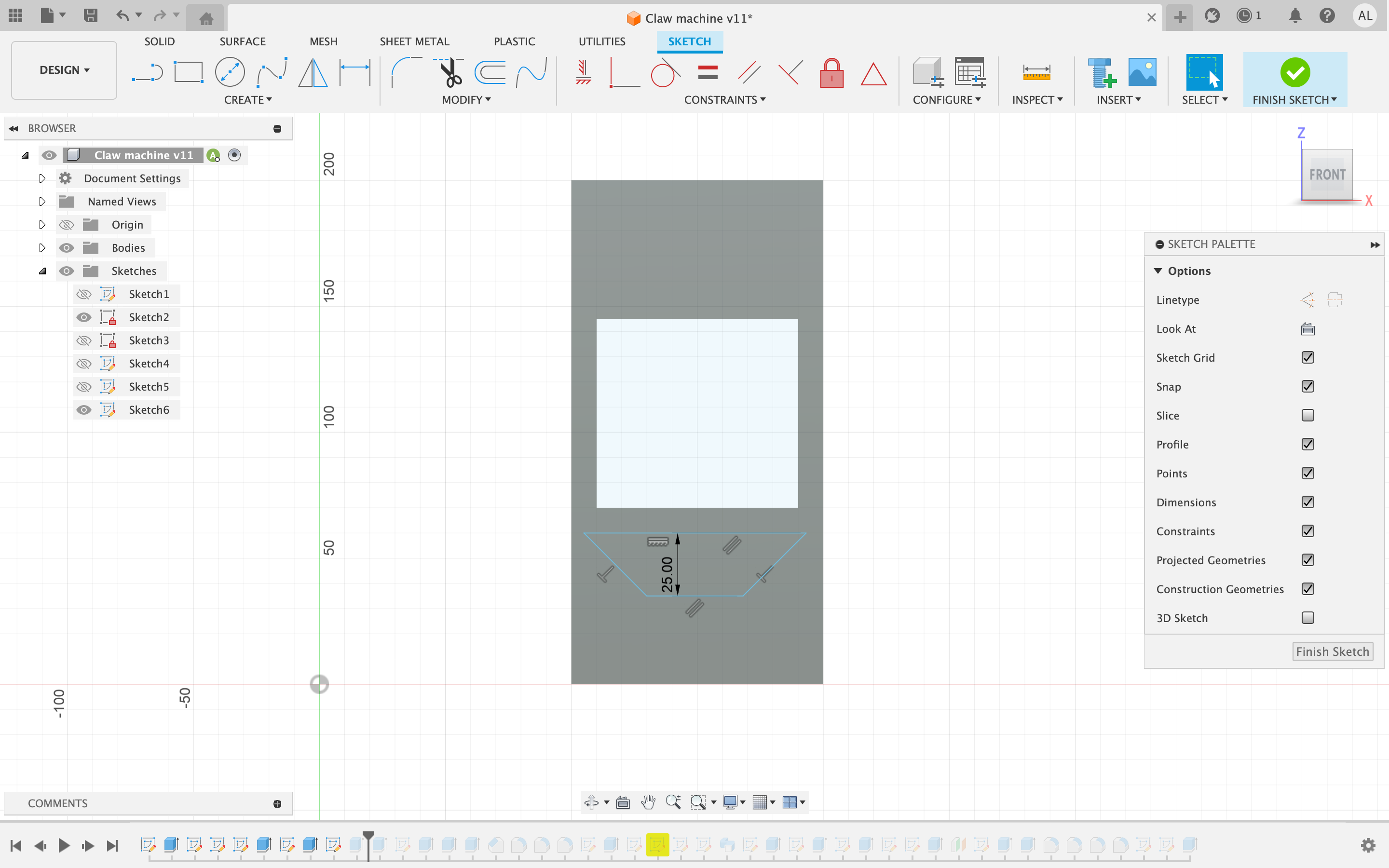
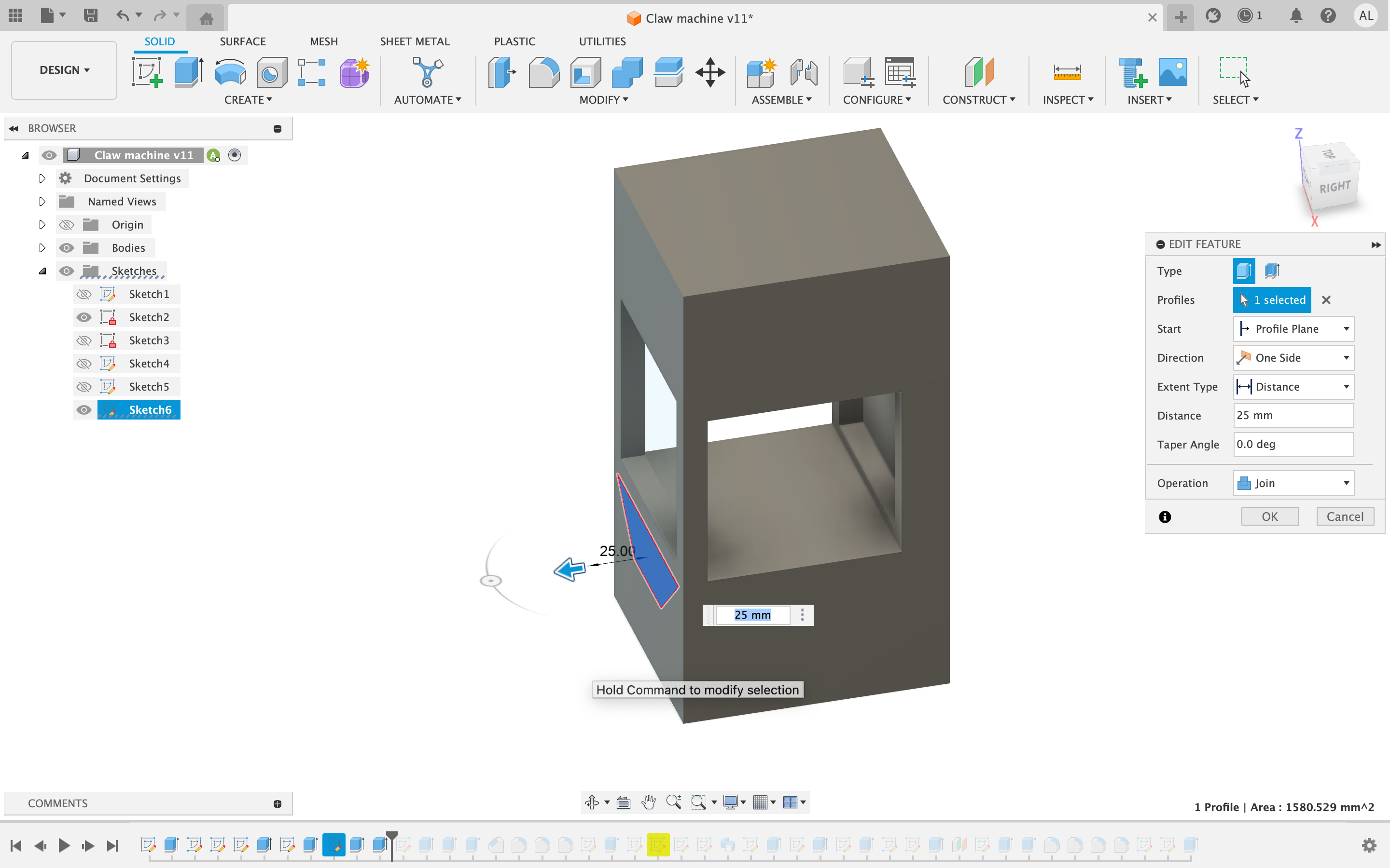
Construct a trapezoid on the front of the structure with a height of 25mm then extrude it by 25mm to create a self.
Joystick and Buttons (Sketch)
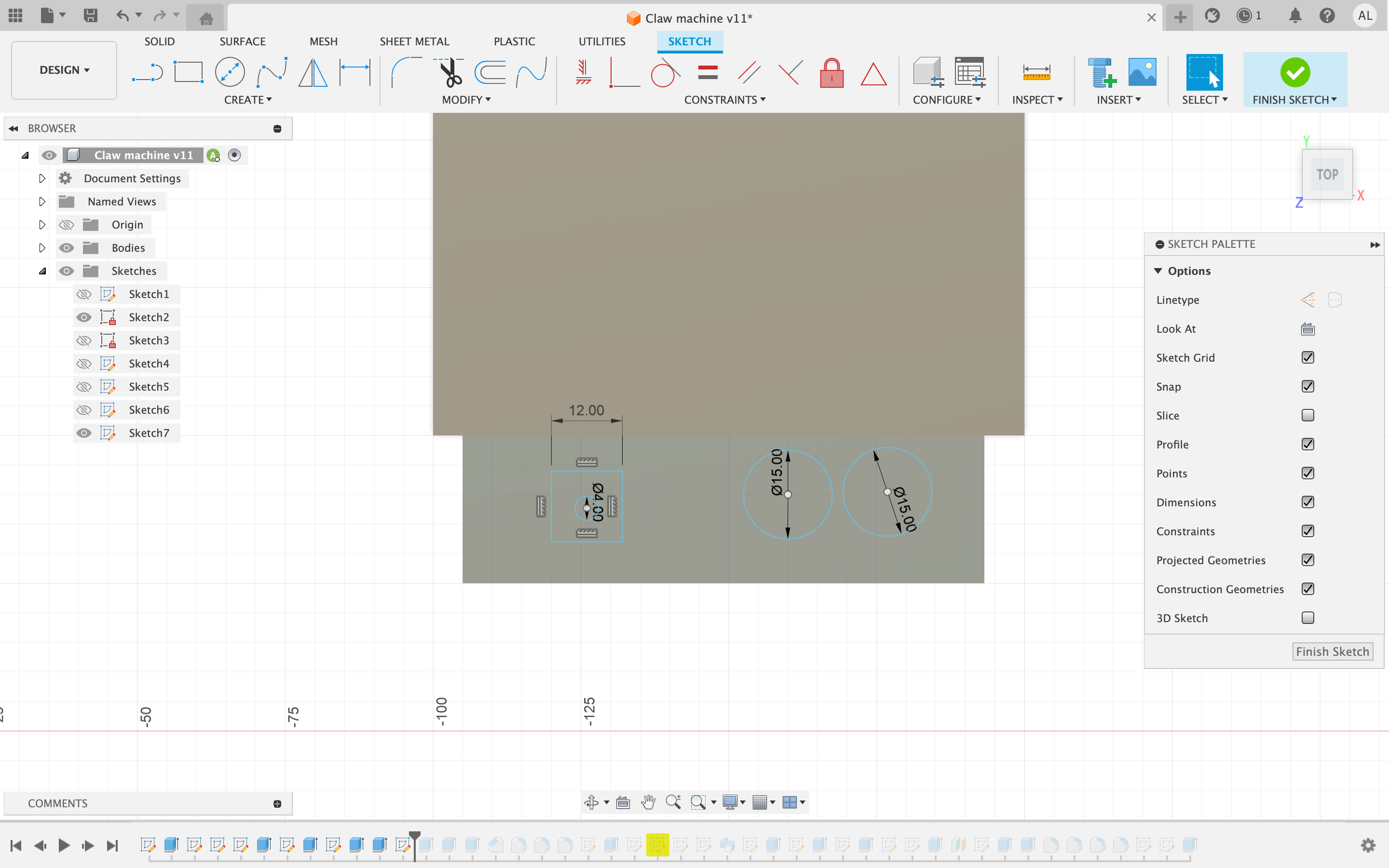
Create a new sketch on top of the extruded trapezoid. Here you can create a square,12 by 12, and two circles both 15mm in diameter. Also you should construct a 4 mm diameter circle within the square for the joystick.
Joystick and Buttons (Exstrude)
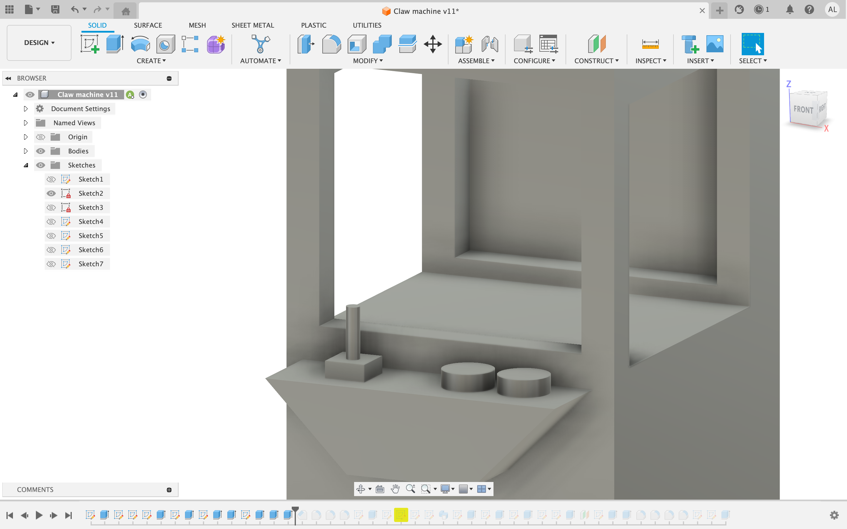
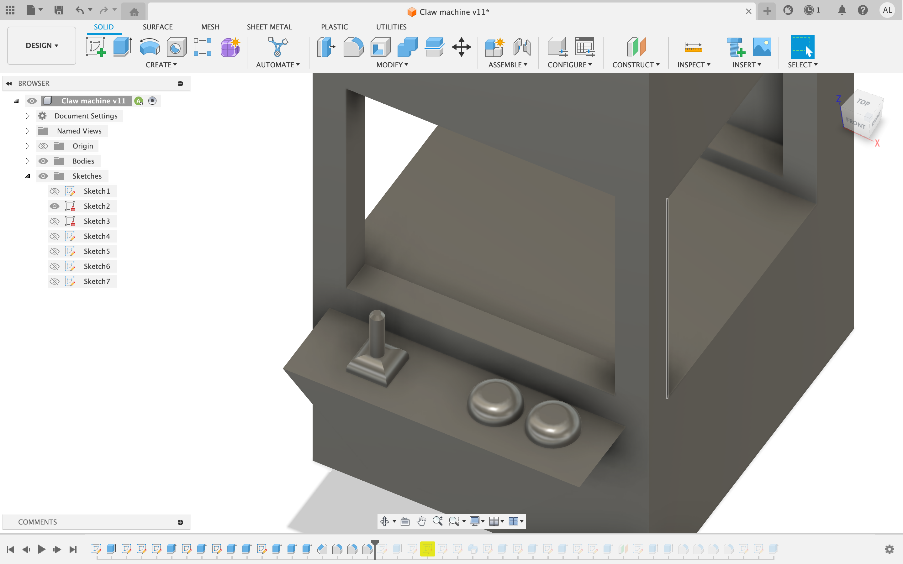
Extrude the square and 15mm circles 5mm upward. While the 4mm circle needs to be extruded by 20mm. Follow this step by filleting the square and circles by a measurement of 4mm and the top of the joystick should be chambered by 1mm.
Creating the Sweep
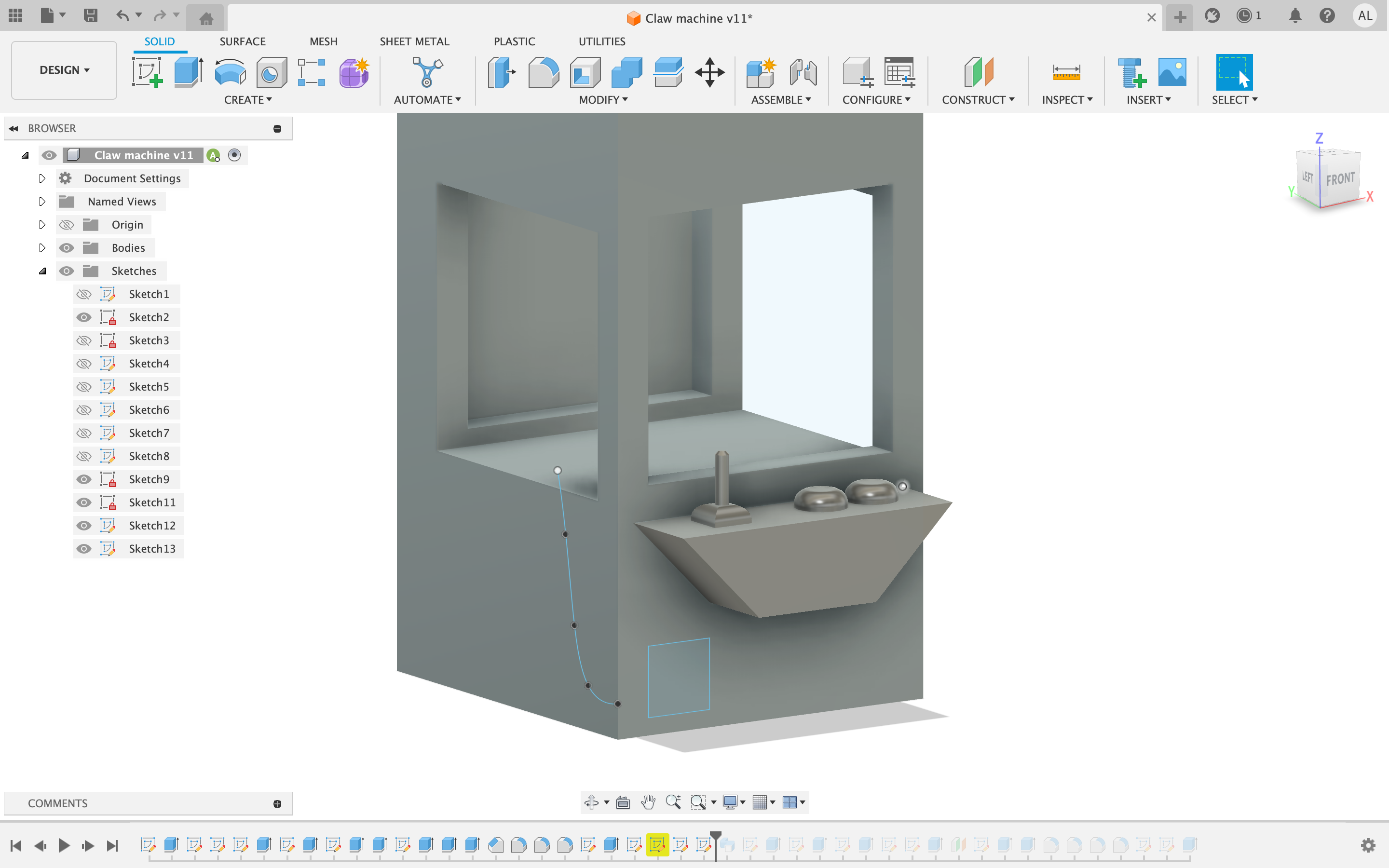
On the front of the machine in the bottom left corner sketch a 20mm by 20mm square. Following this sketch, a spline on the left face of the structure going upwards wising just above the base of the inside. Following these two sketches create a cut sweep using the square as the profile and the spline as the path. This represents the shoot a prize would slide out of.
(Optional Design for Looks)
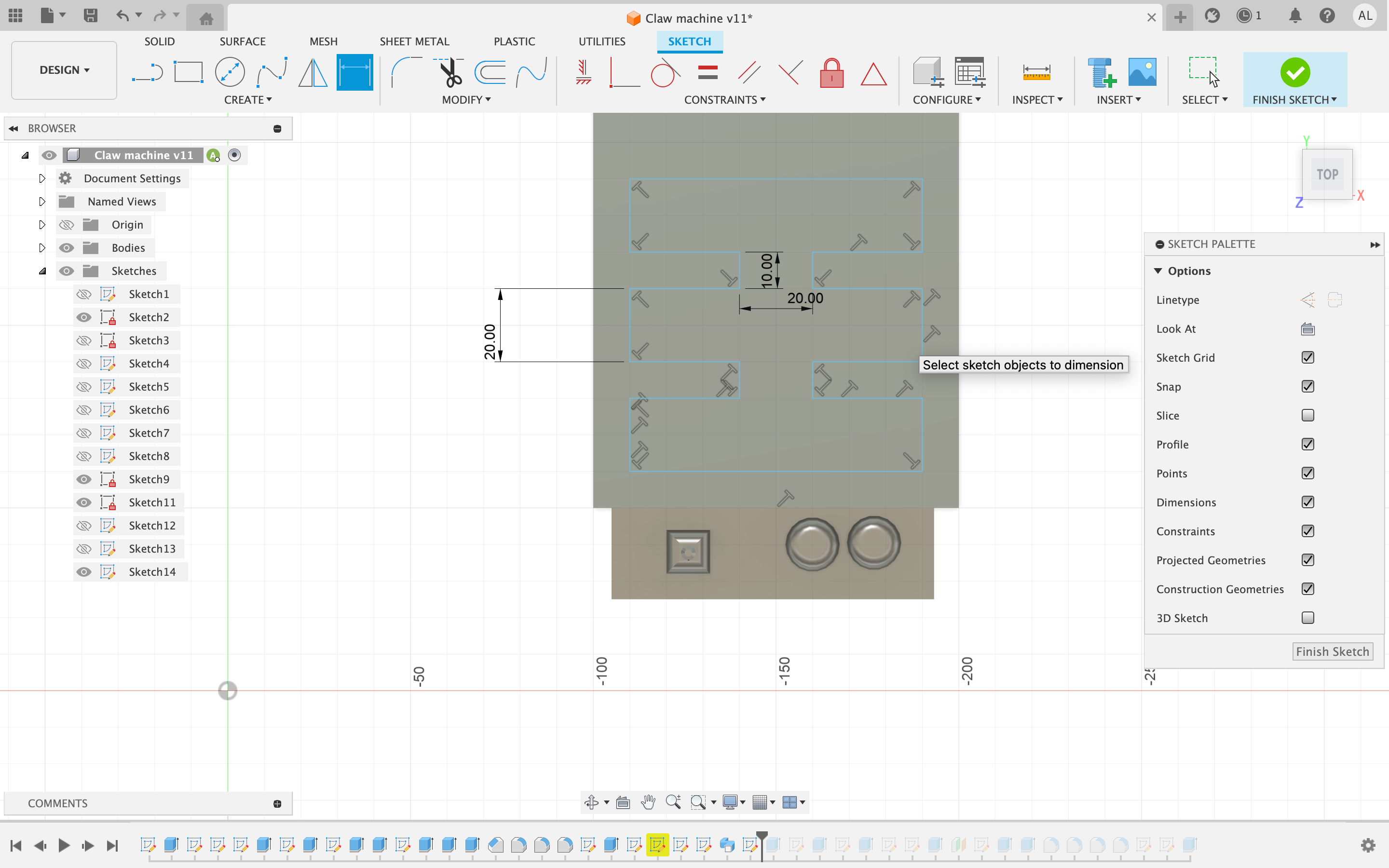
On the top of the structure, I created three rectangles 20mm in height a piece connected by 10 mm by 20mm segments to construct an interesting shape at the top of the model. I then extruded the sketch inward by negative 40 at a taper angle of -5
Putting Words on the Buttons
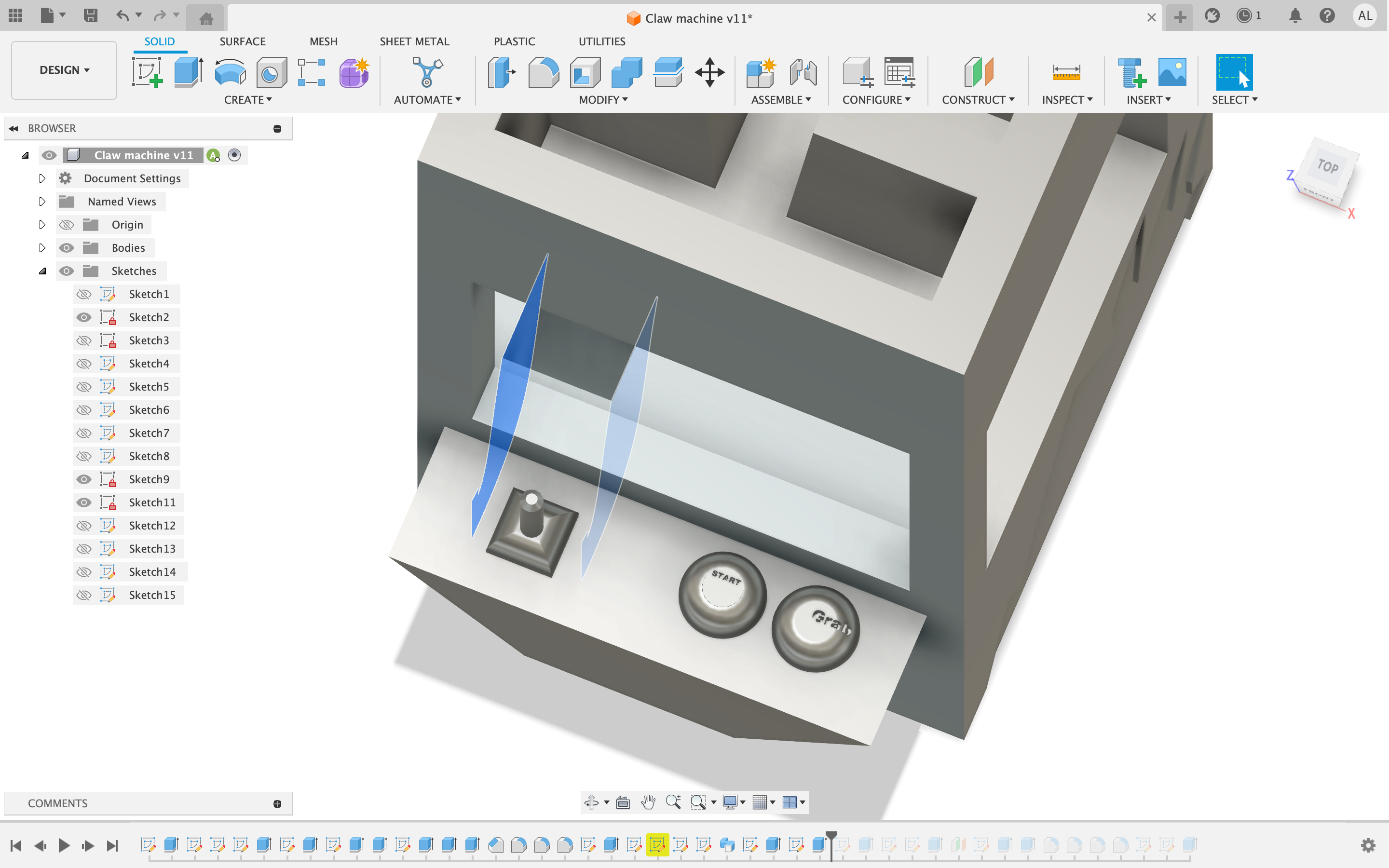
This step is simple create a new sketch and insert text on the buttons. I used Areal Black at 2m font size. I chose the words Start and Grab but you can customize your own words for this step.
Putting Up Walls
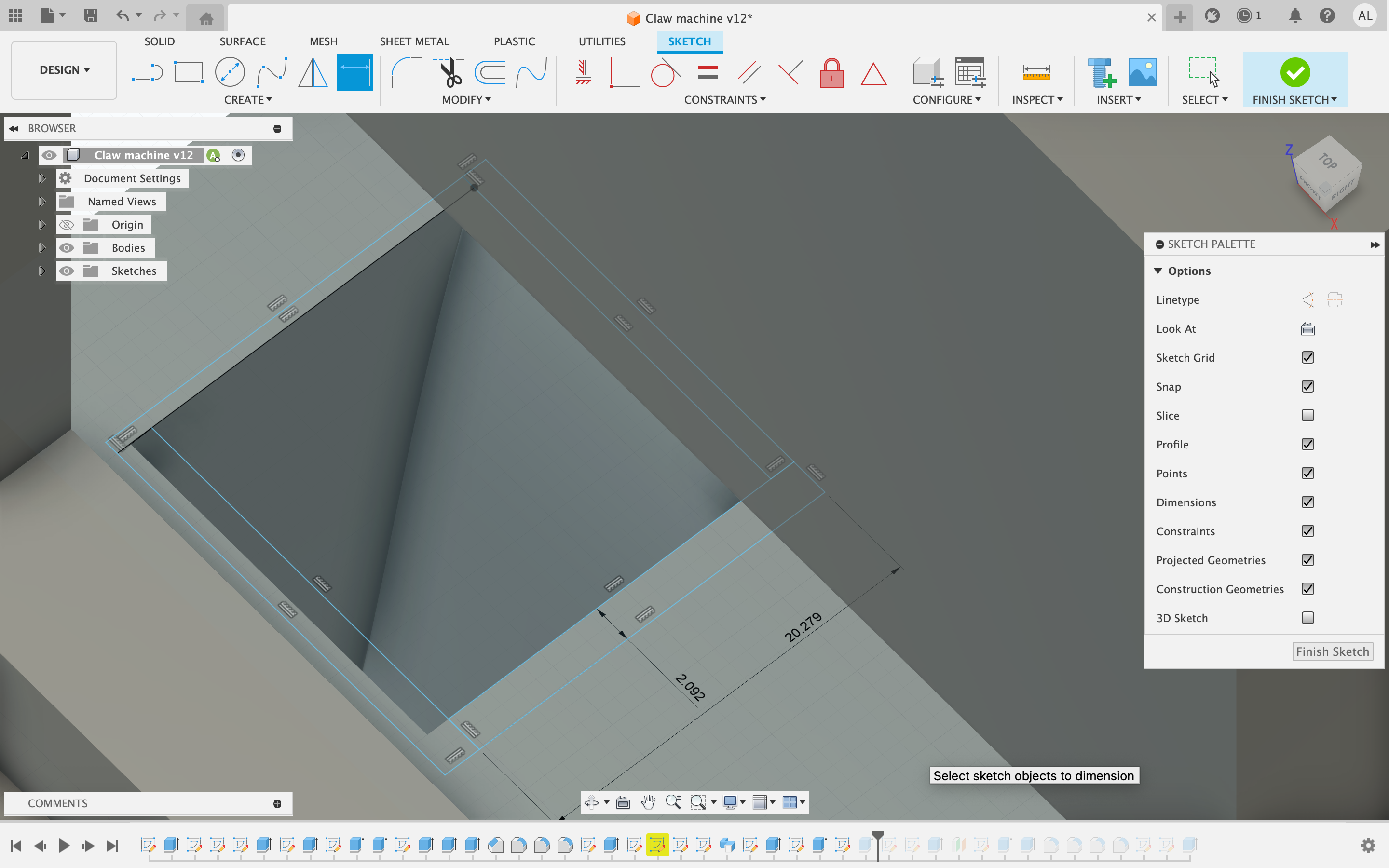
Construct four small rectangles 20.3 by 2.1 mm around the sweep to create walls. These shapes should be extruded by 6mm
Creating the Arm and Claw (Difficult)
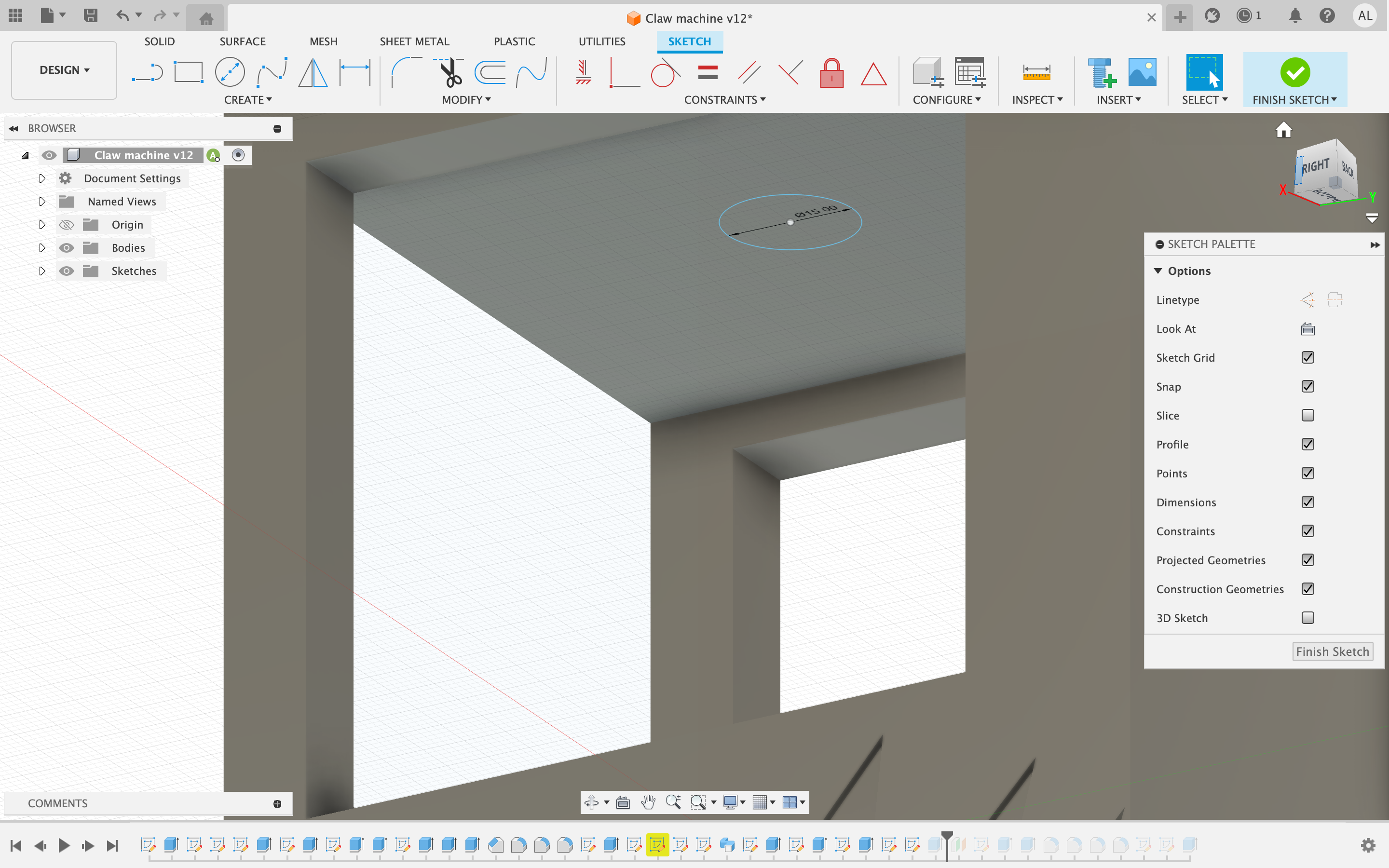
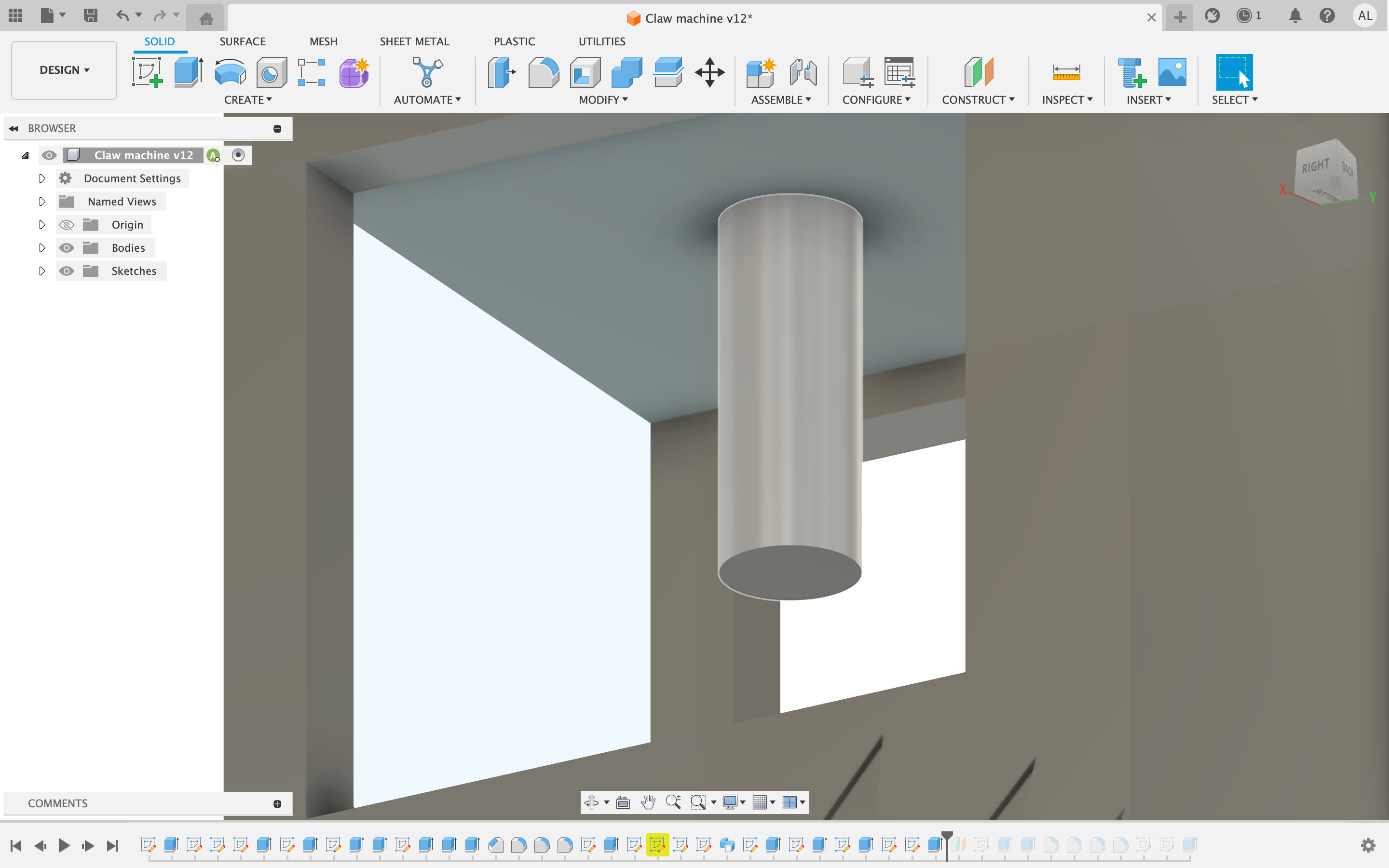
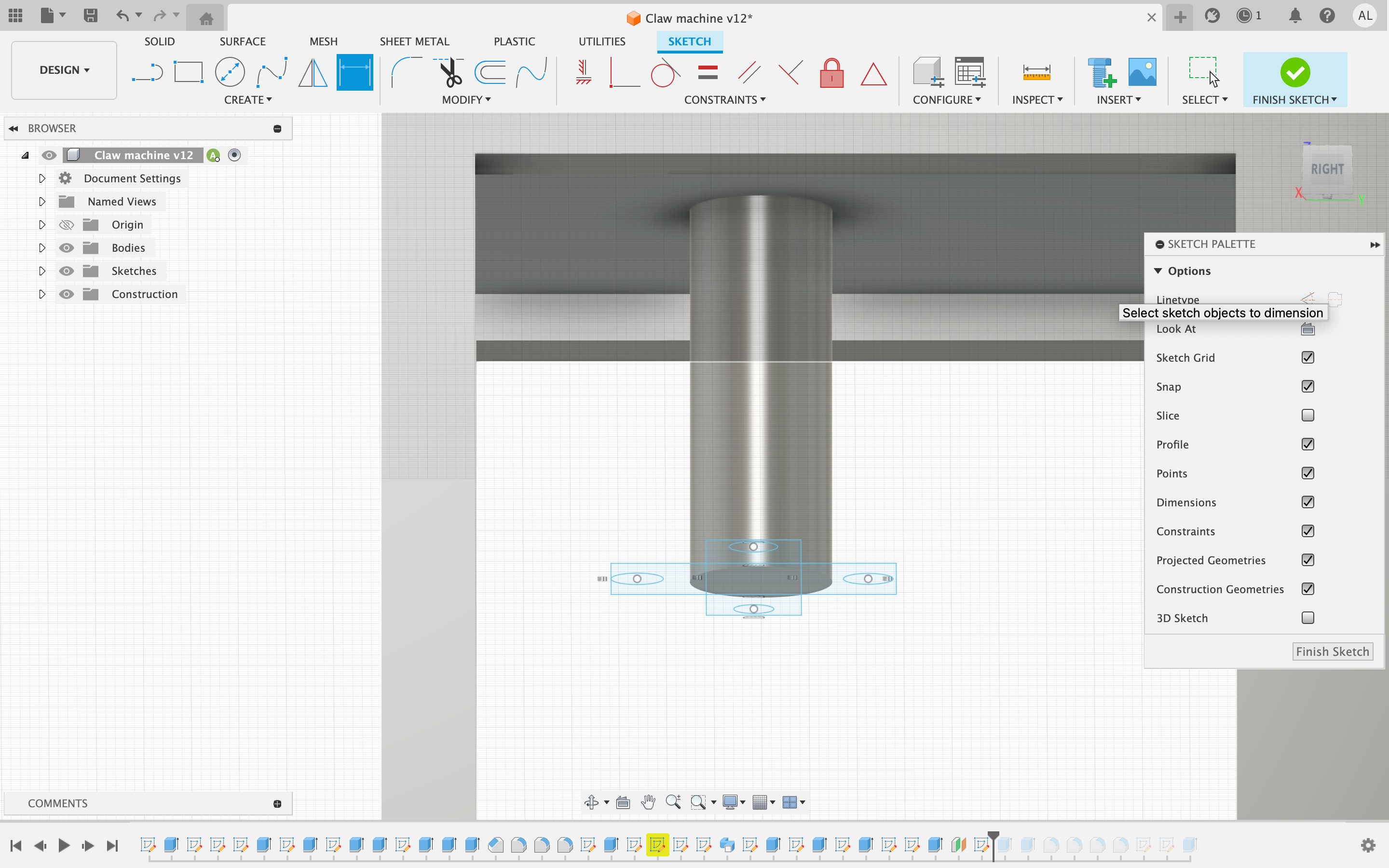
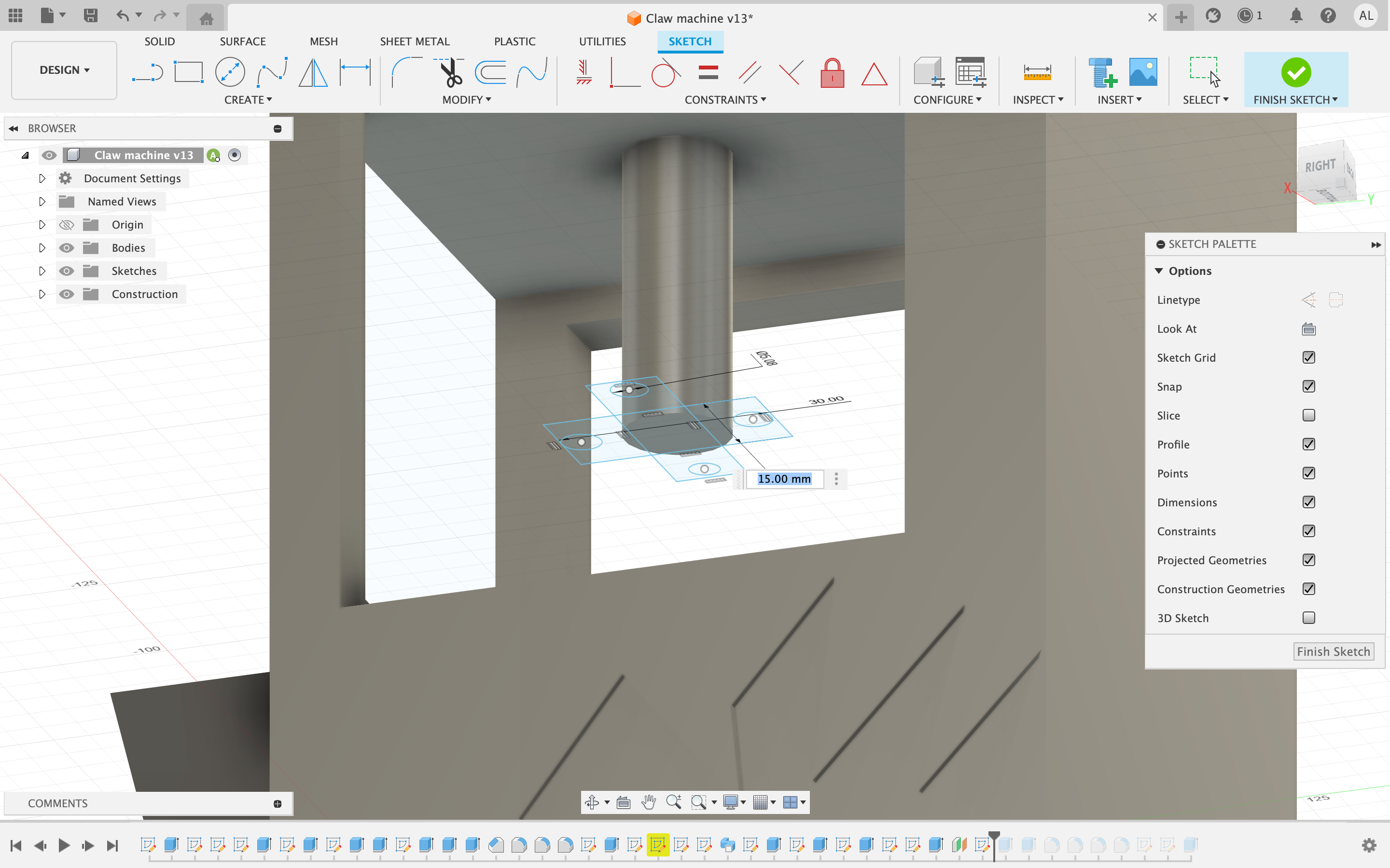
On the inside roof of the structure, as close to the center as possible sketch a 15 mm diameter circle then extrude it by 40mm to create the arm. For the claw, you will have to create an offset plane extending from the inside roof down 40mm to the bottom of the arm. On the offset plane draw a plus symbol using rectangles with dimensions 30mm by 15mm. Within these rectangles at the ends construct 5mm diameter circles for the claw.
Fisnihing the Claw
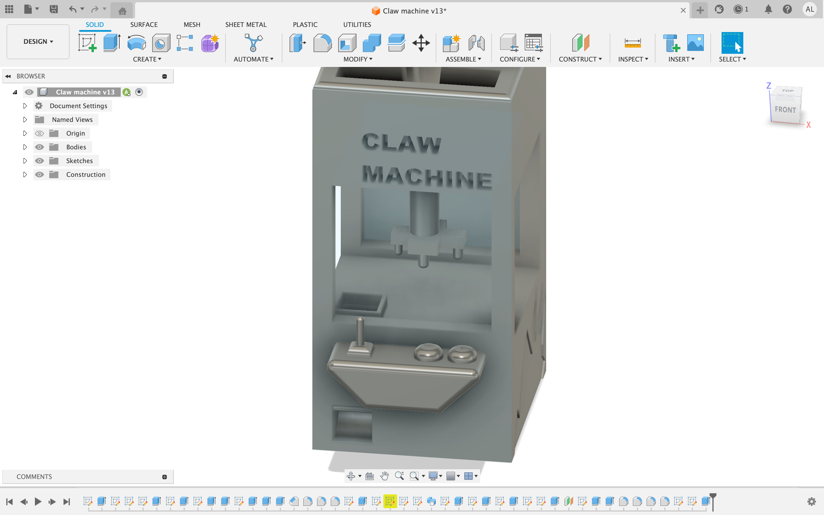
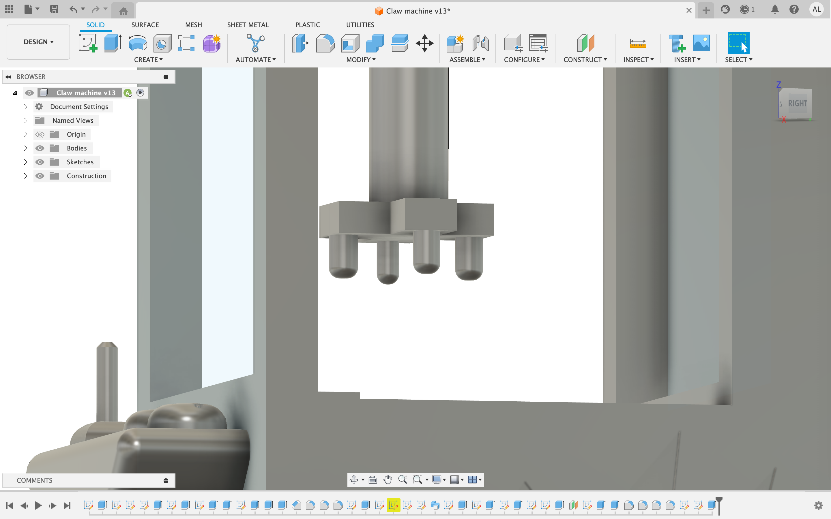
Exsrrude the rectangles by 6mm and the circles by 14 mm. Finally fillet the end of the cylinders you just extruded by 4mm and add a 4mm to the trapezoid on the front. Now the final step is to add text above the front window Reading Claw Machine. Recommended font is Ariel Black with a font size of 9. Now you have a completed claw machine model