Function Generator

A function generator in electrical engineering is typically a piece of electronic test gear or software used to produce various electrical waveforms over a broad range of frequencies. The sine wave, square wave, triangle wave, and sawtooth waveforms are some of the most popular waveforms created by the function generator. They come in both repeated and one-shot waveforms (which requires an internal or external trigger source). The option to add a DC offset is another feature found on many function generators. Integrated circuits (ICs) that produce waveforms are sometimes referred to as function generators.
Supplies

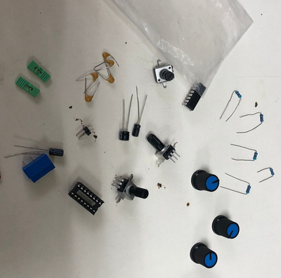
- • Potenciometers
- • Diodes
- • Capacitors
- • Resistors
- • OpAmp IC XR2206
- • DC Header
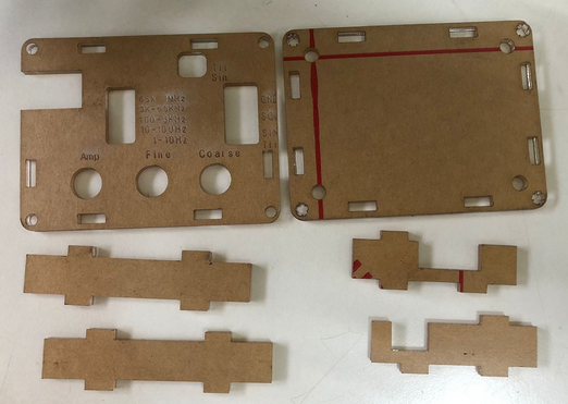
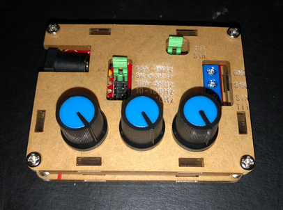
- • 3D Printed Case
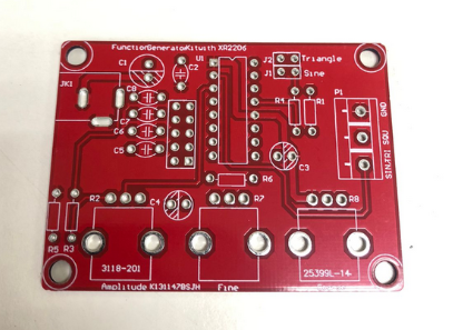
- • PCB
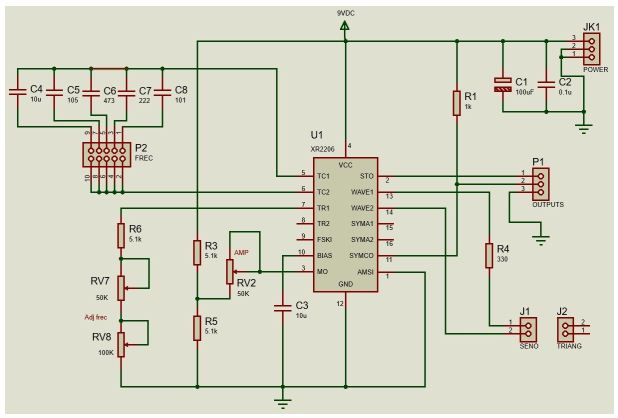
Circuit Design
First the design of our circuit was made on fritzing, this is because the IC was already premade on the software and it gave us an advantage.
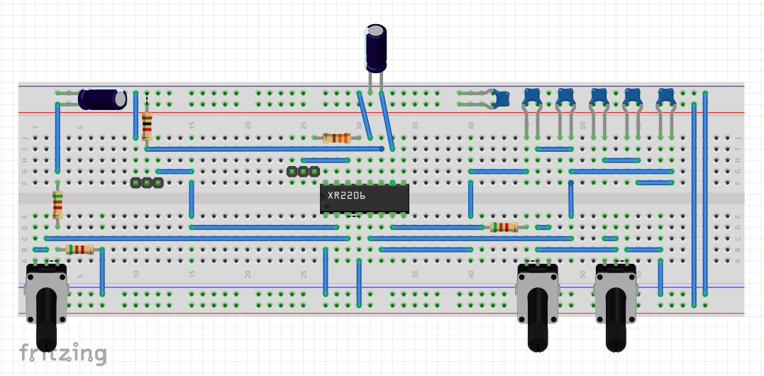
Breadboard Testing
We also made a version on the breadboard for testing.
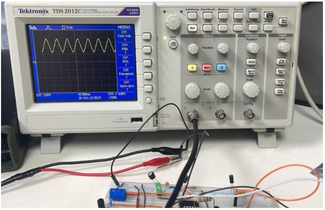
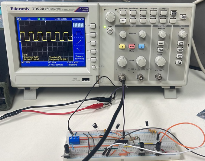
Oscilloscope and Circuit Testing
After getting all the components and checking every connection we started testing with the oscilloscope to finally start soldering it into the PCB

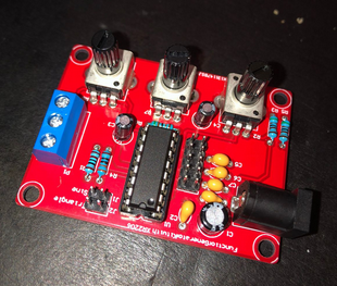
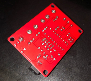
Soldering Components on PCB
Next, we will present the process of soldering to the PCB where we took turns soldering each corresponding element. It should be noted that we had some problems when soldering the potentiometers, since the pin holes were very large, therefore, it was necessary to put a lot of solder so that it can have a good conduction in the circuit.