FumeFan Medi, Max & Max PRO KITs Fume Extractor Assembly Instructions
by hertzgamma in Circuits > Soldering
2413 Views, 38 Favorites, 0 Comments
FumeFan Medi, Max & Max PRO KITs Fume Extractor Assembly Instructions
Hi! You probably are one of the amazing people who supported our Kickstarter campaign - The fumeFan. If you missed the campaign you can find more about the fumeFan on maketechnics.com.
This instructable describes how to assemble your fumeFan Medi, Max or Max PRO KIT step by step.
Start with getting the following:
- Soldering iron and soldering wire
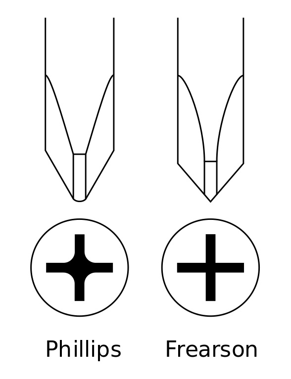
- Small (Size #00) Phillips or Frearson screwdriver
KIT Contents
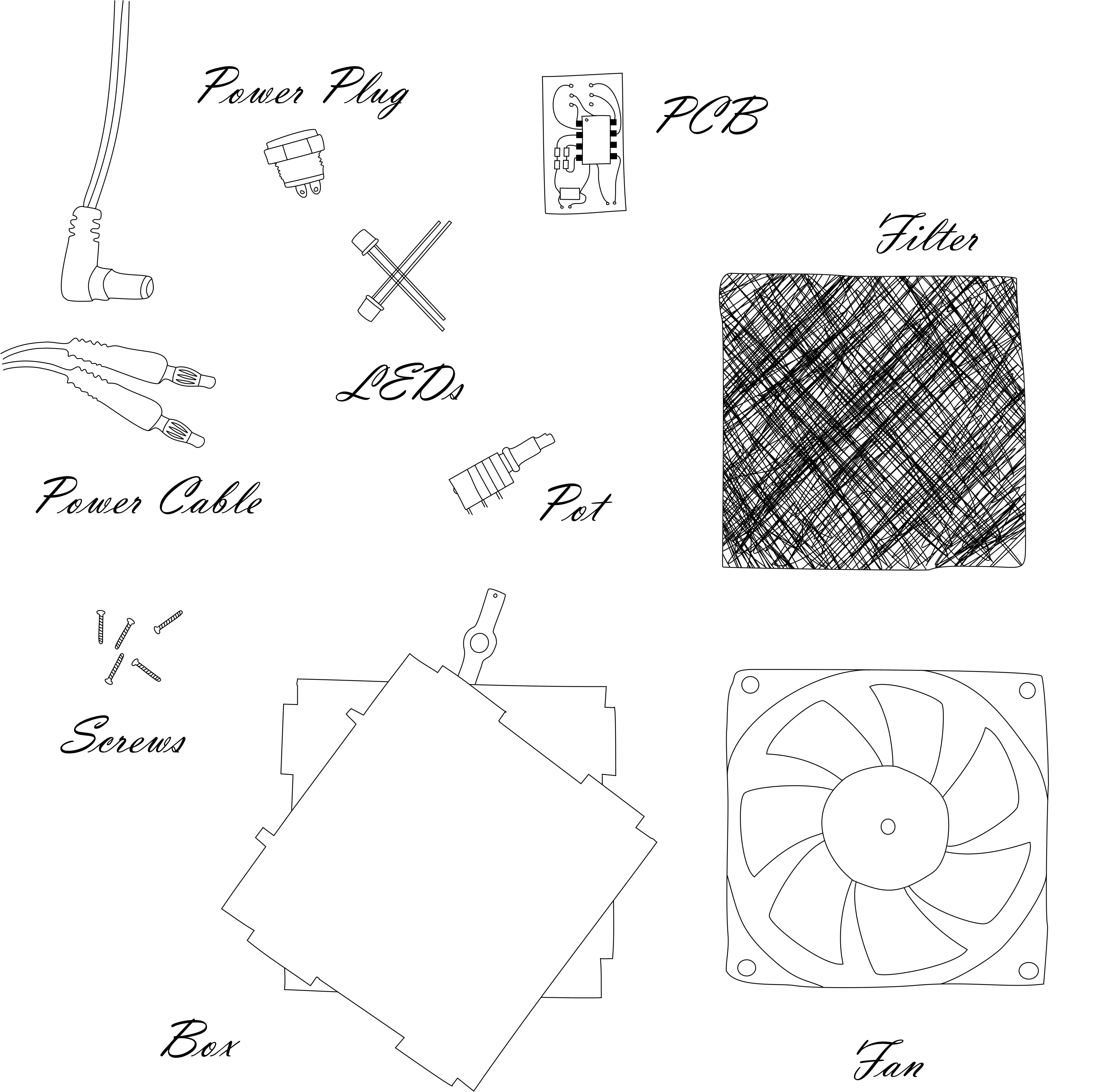

What you have in the box is:
- Fan
- Filters
- Plastic enclosure parts
- Power plug
- Banana plug power cable
- PCB Kit
- Potentiometer
- LEDs assembly
- Screws
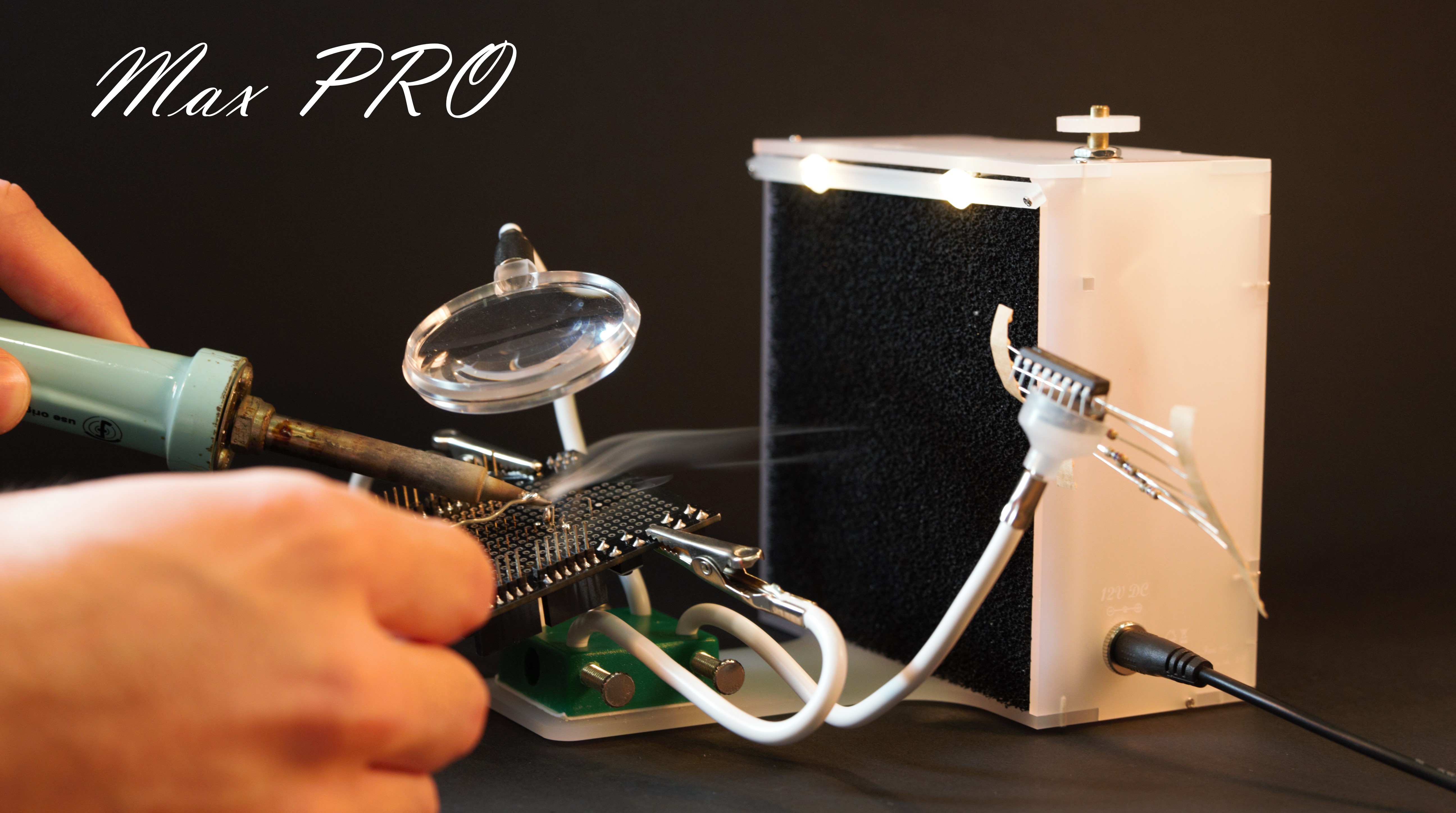
- Helping hands*
NOTE* Applies to Max PRO models only
Solder the PCB
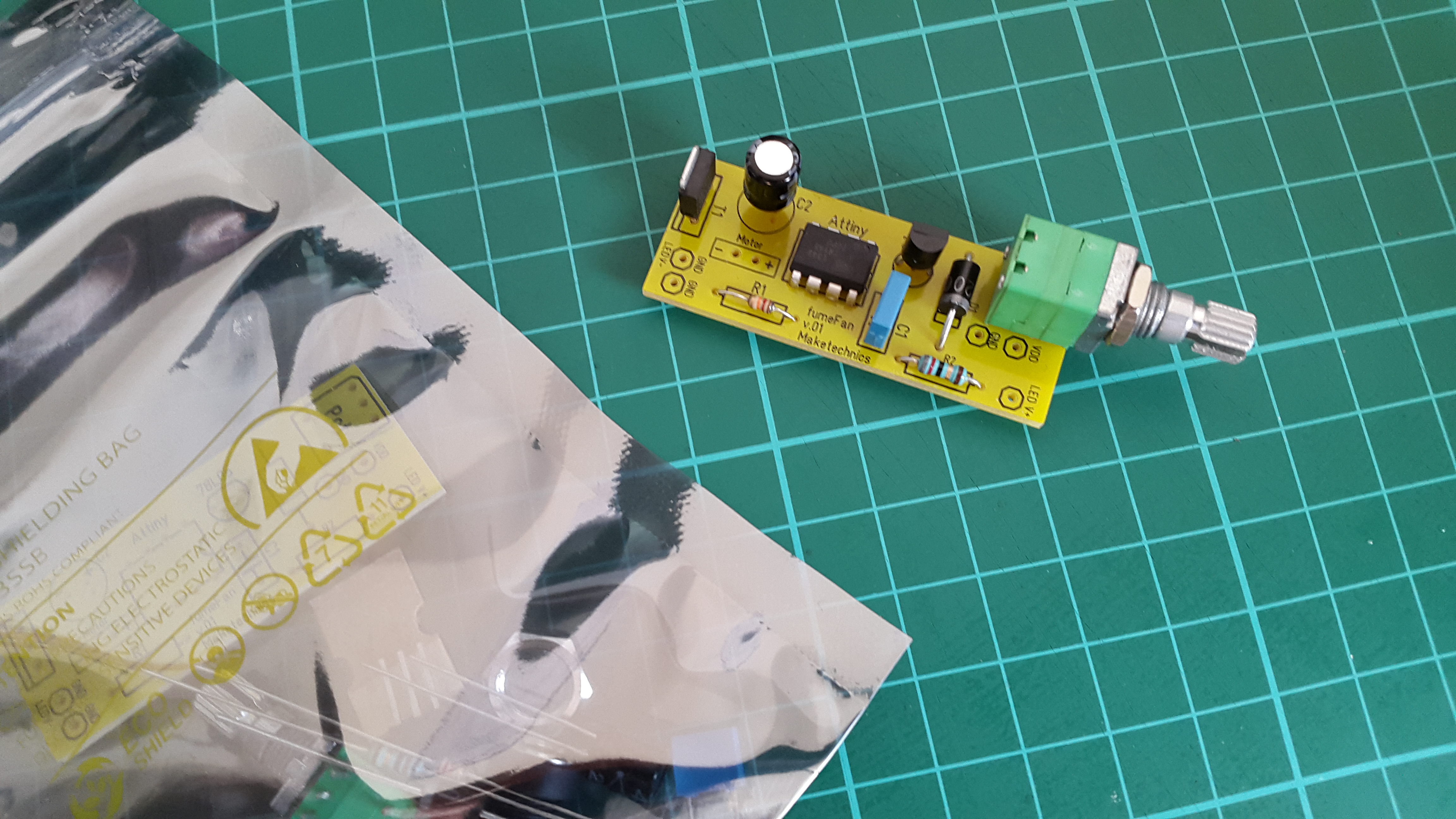
Check this link for the instructions on how to assemble the PCB.
https://www.instructables.com/id/How-to-Solder-Your-fumeFan-PCB-KIT/
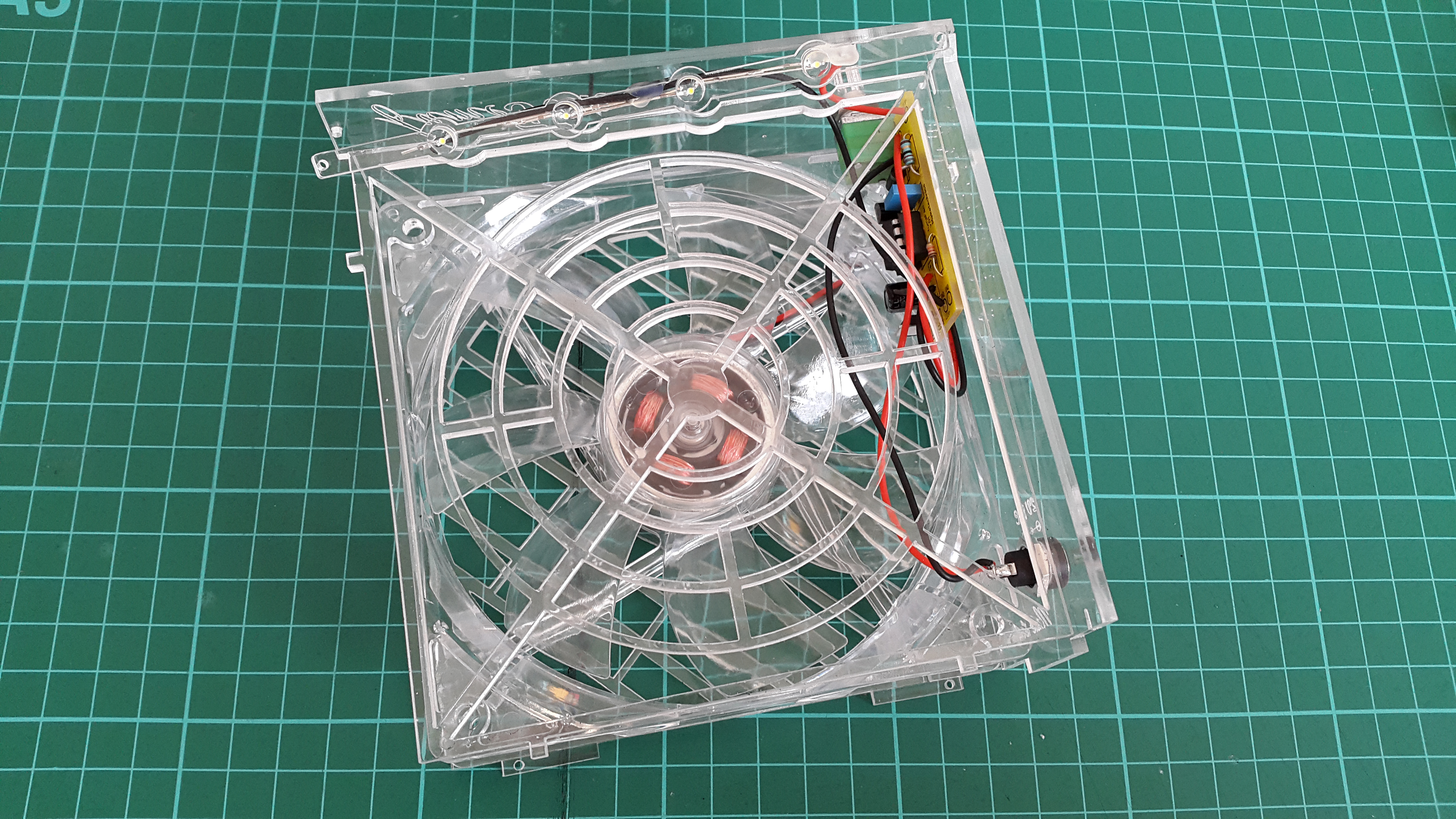
Connect Fan
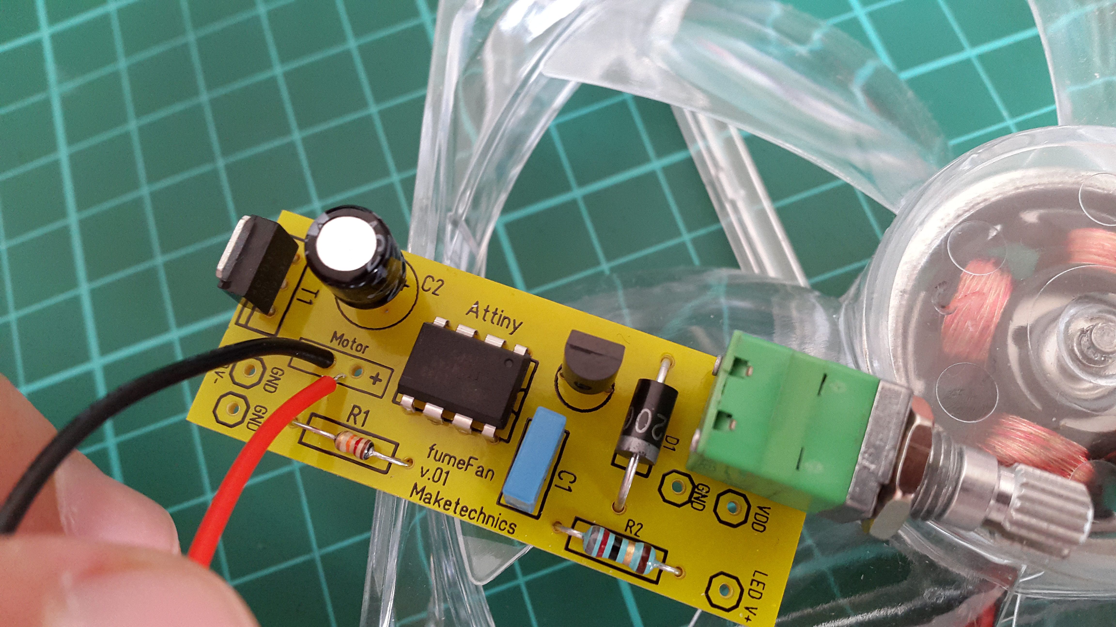
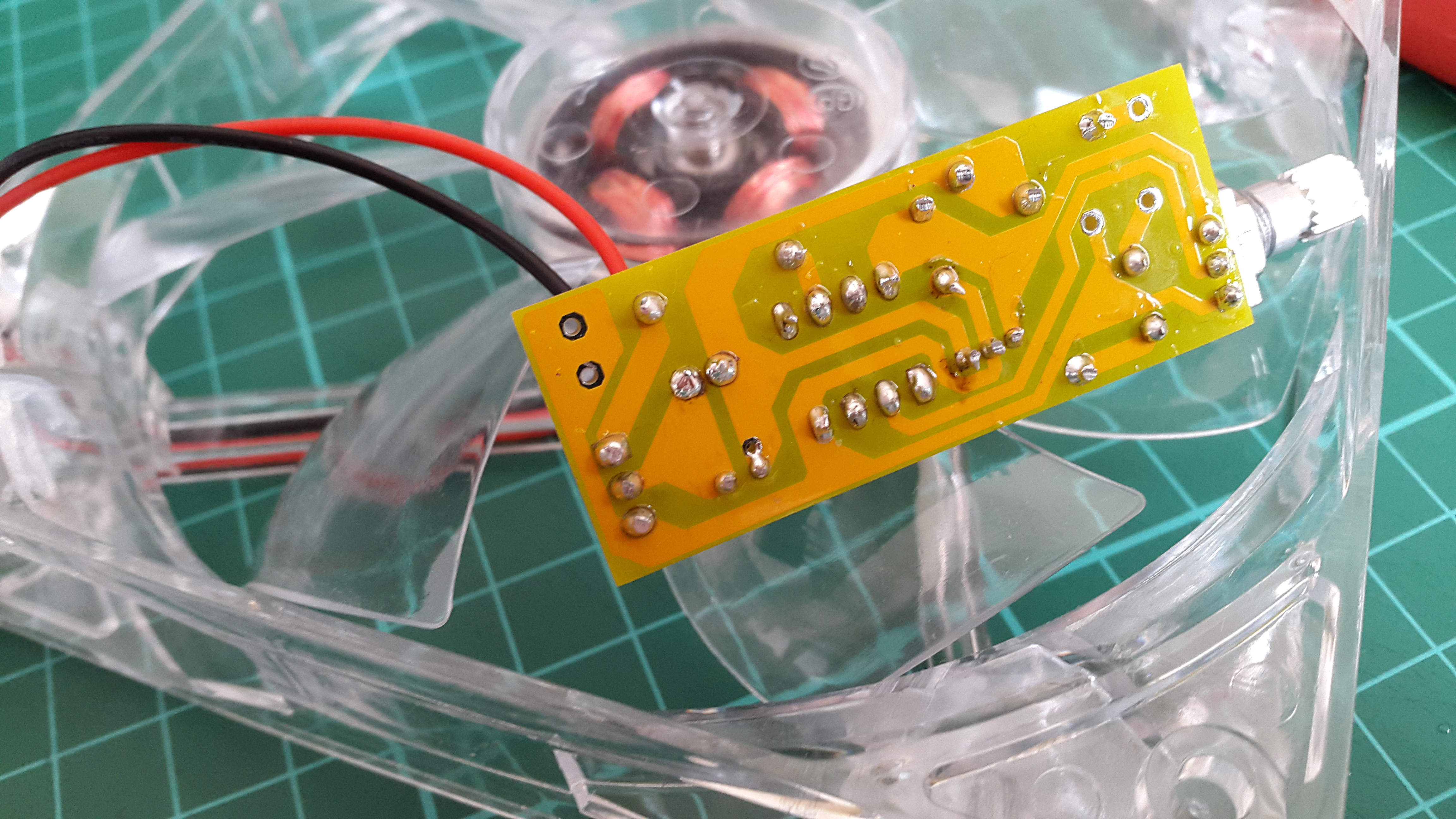
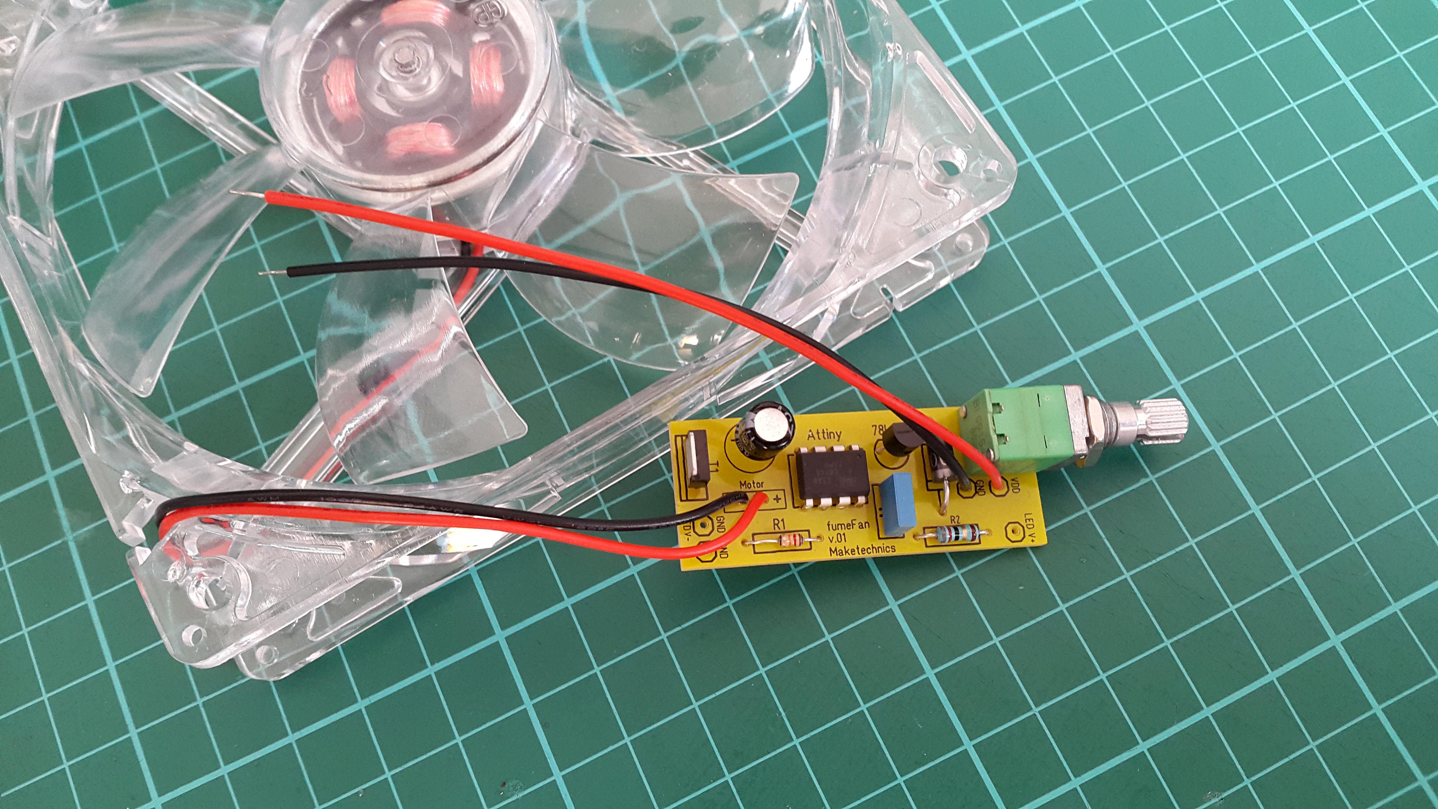
Solder the fan wires (already cut to exact length) to the PCB terminals marked "Motor +/-".
- "+" - Red
- "-" - Black
Connect Power
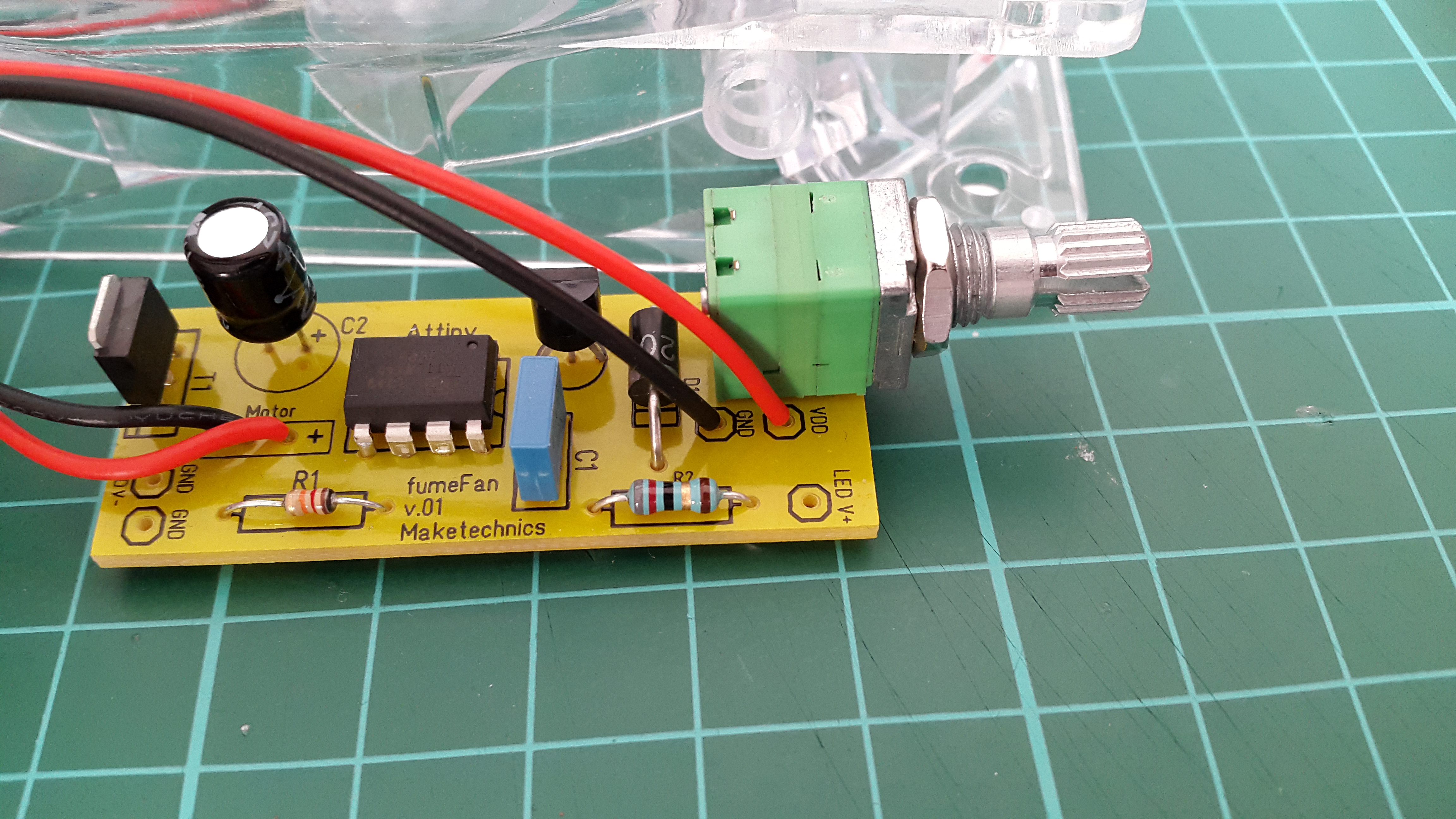
Solder one end of the power supply wires (already cut to exact length) to the PCB terminals marked "VDD" and "GND".
- "VDD" - Red
- "GND" - Black
Install Power Plug
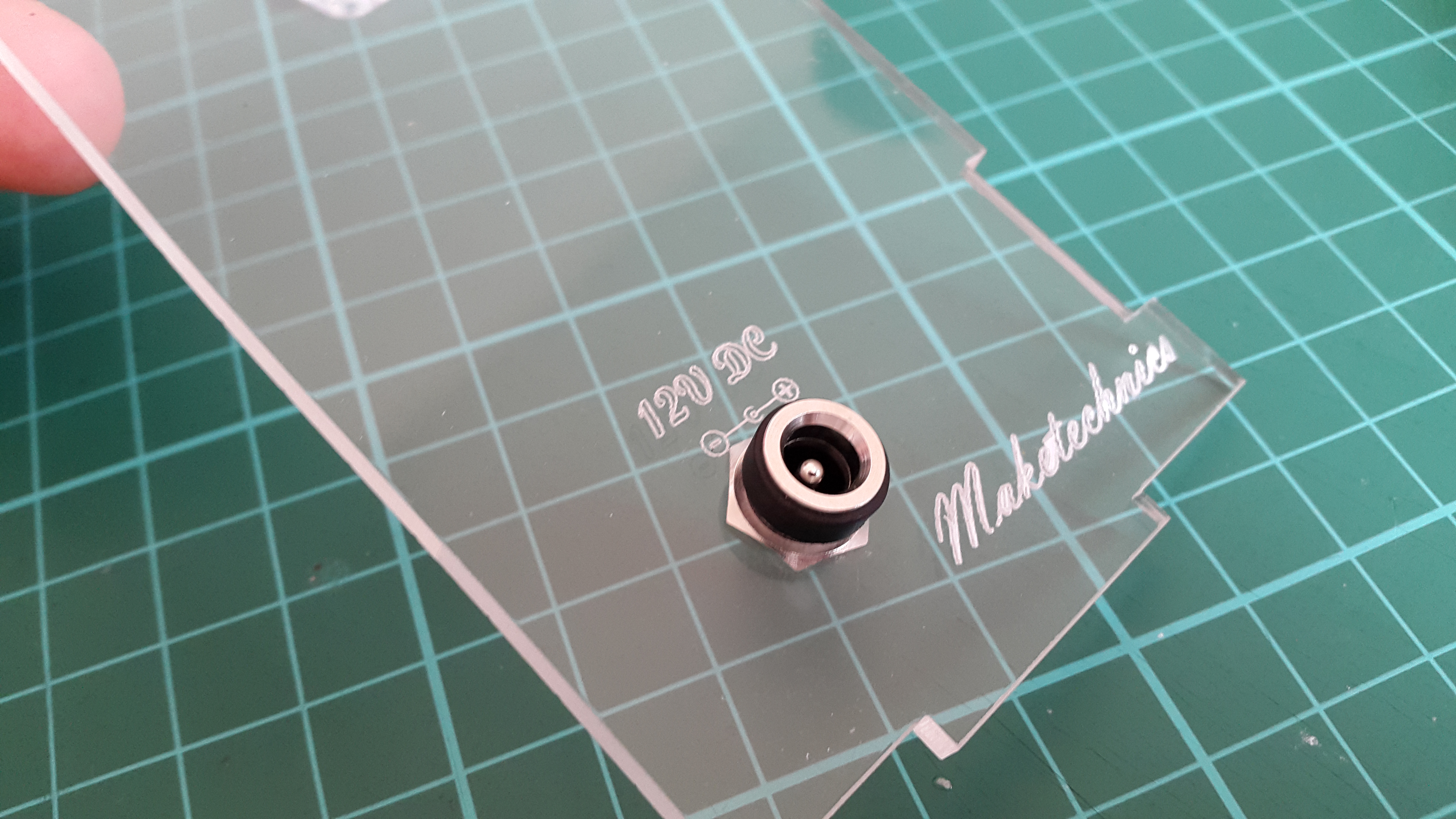
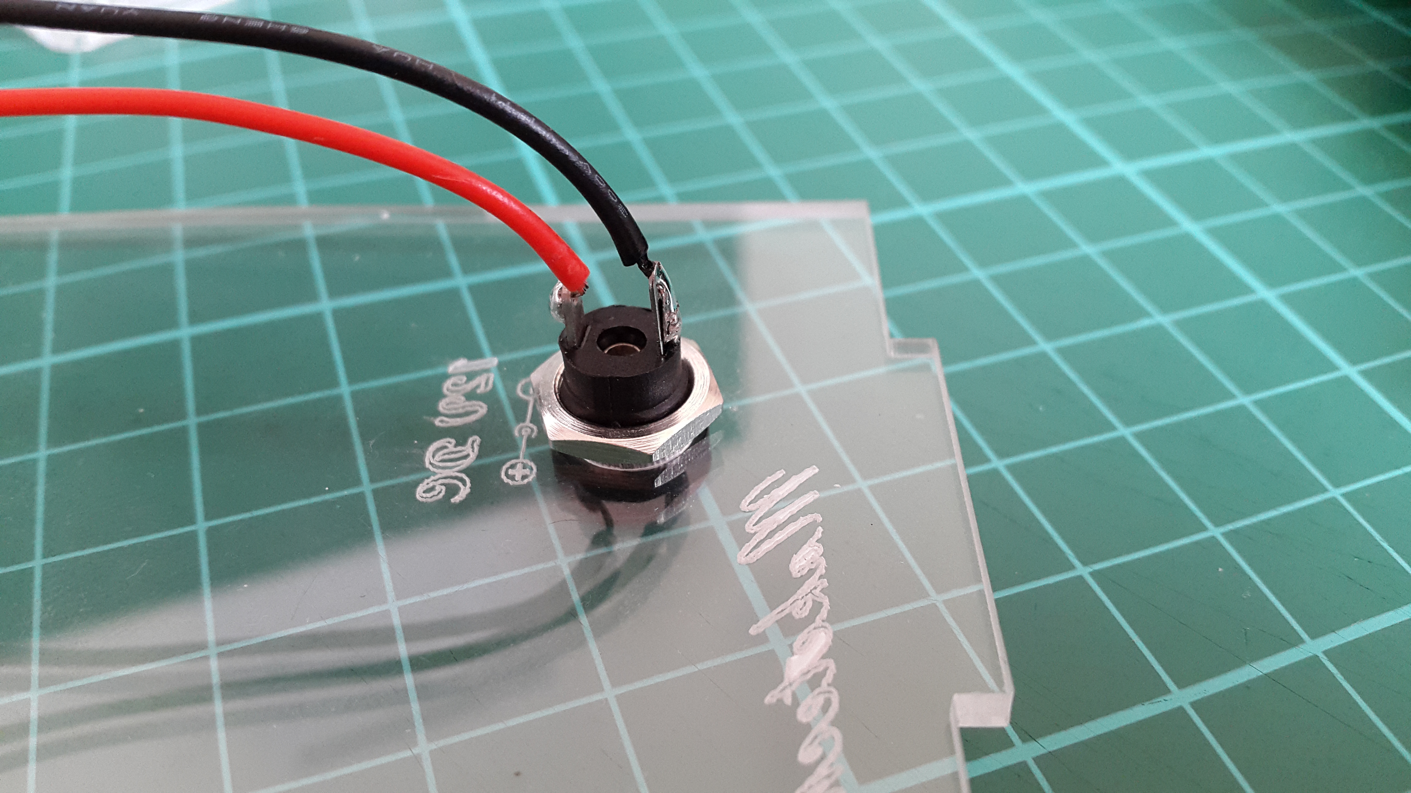
Locate the plastic side that has the "Maketechnics" logo on it.
Insert the power plug through the hole and screw the nut on the back.
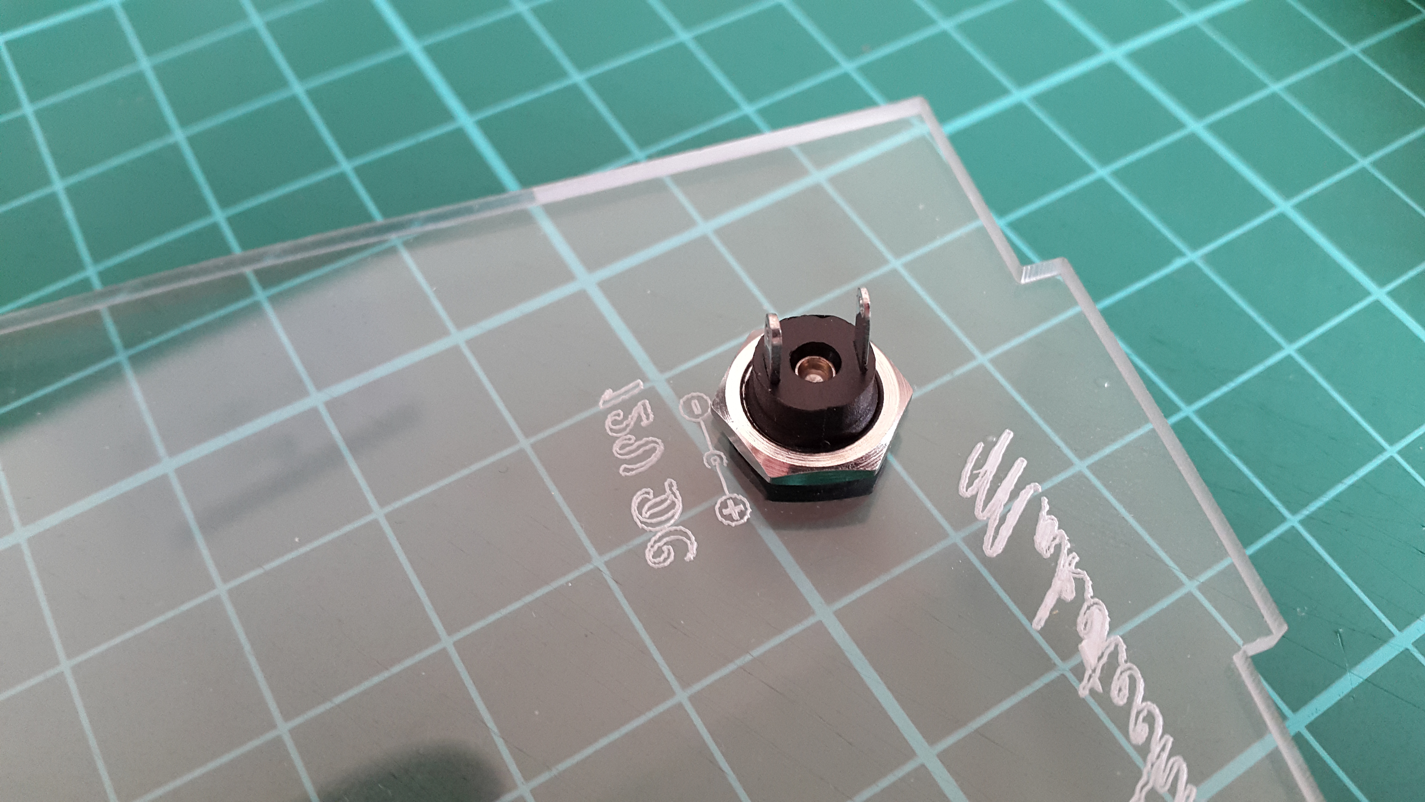
Solder the two power leads to the plug.
NOTE* The way you solder the two cables matters! The pins on the power plug are different size.
- Solder the red lead (positive) to the shorter leg.
- Solder the black lead (negative) to the longer leg.
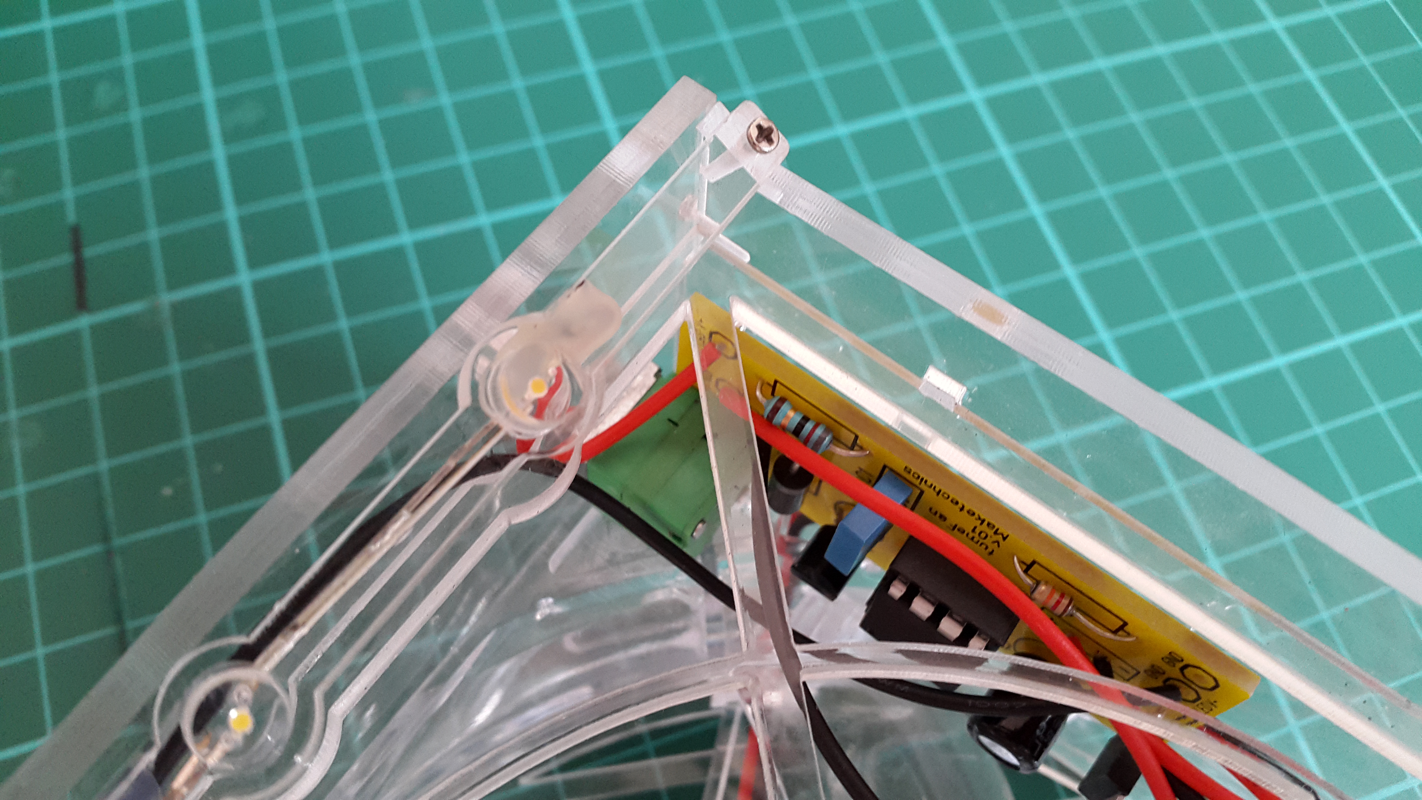
Solder the LED Assembly
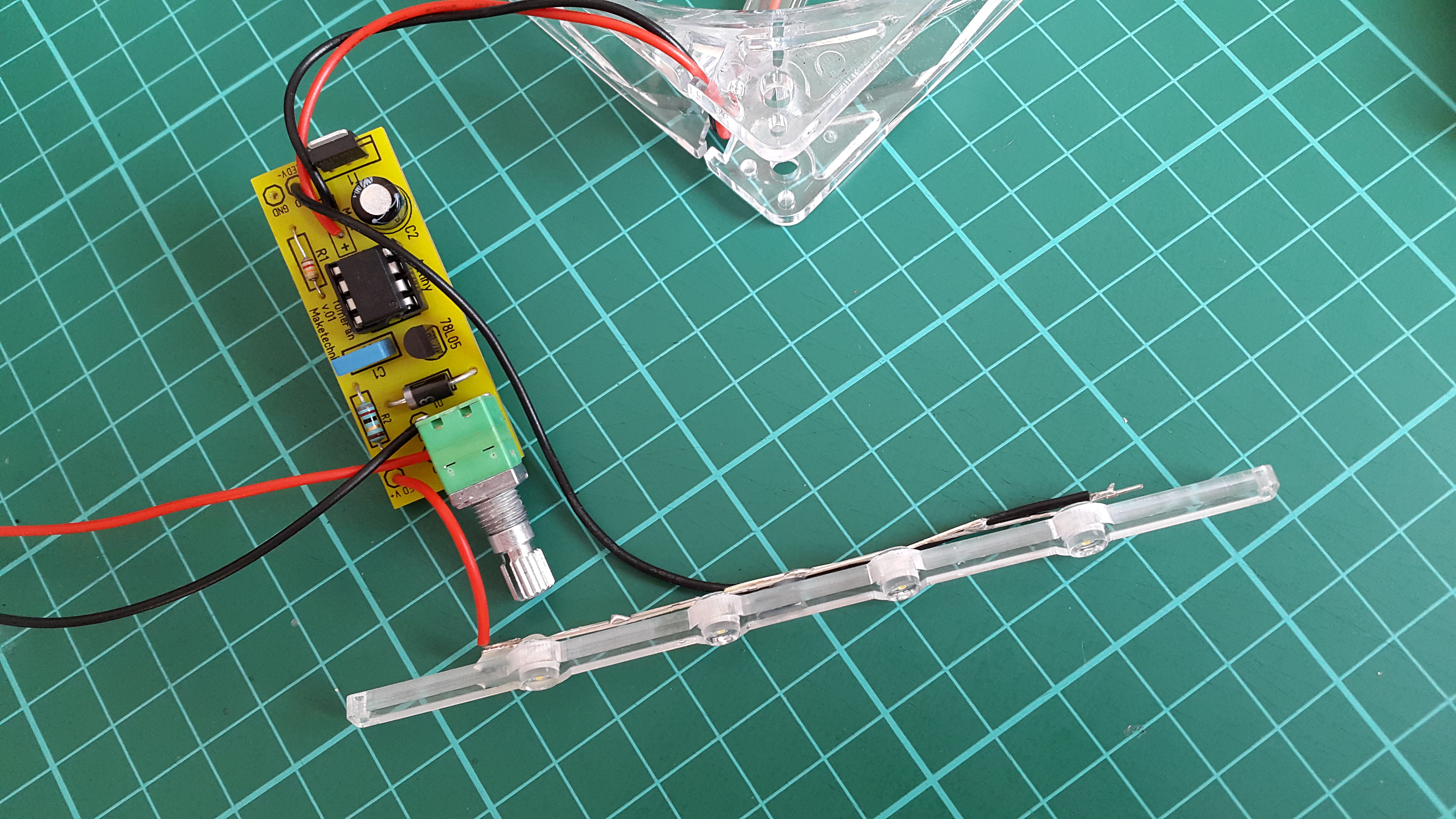
The LEDs are already assembled and glued together with the plastic part that holds them. Solder the black and red cables to the terminals on the PCB marked LED V- and LED V+.
- "LED V+" - Red
- "LED V-" - Black
Put Three Sides Together
Locate the back cover and snap it into place. The logo on it will be seen horizontal when the side with the "fumeFan" logo is on top.
Tighten
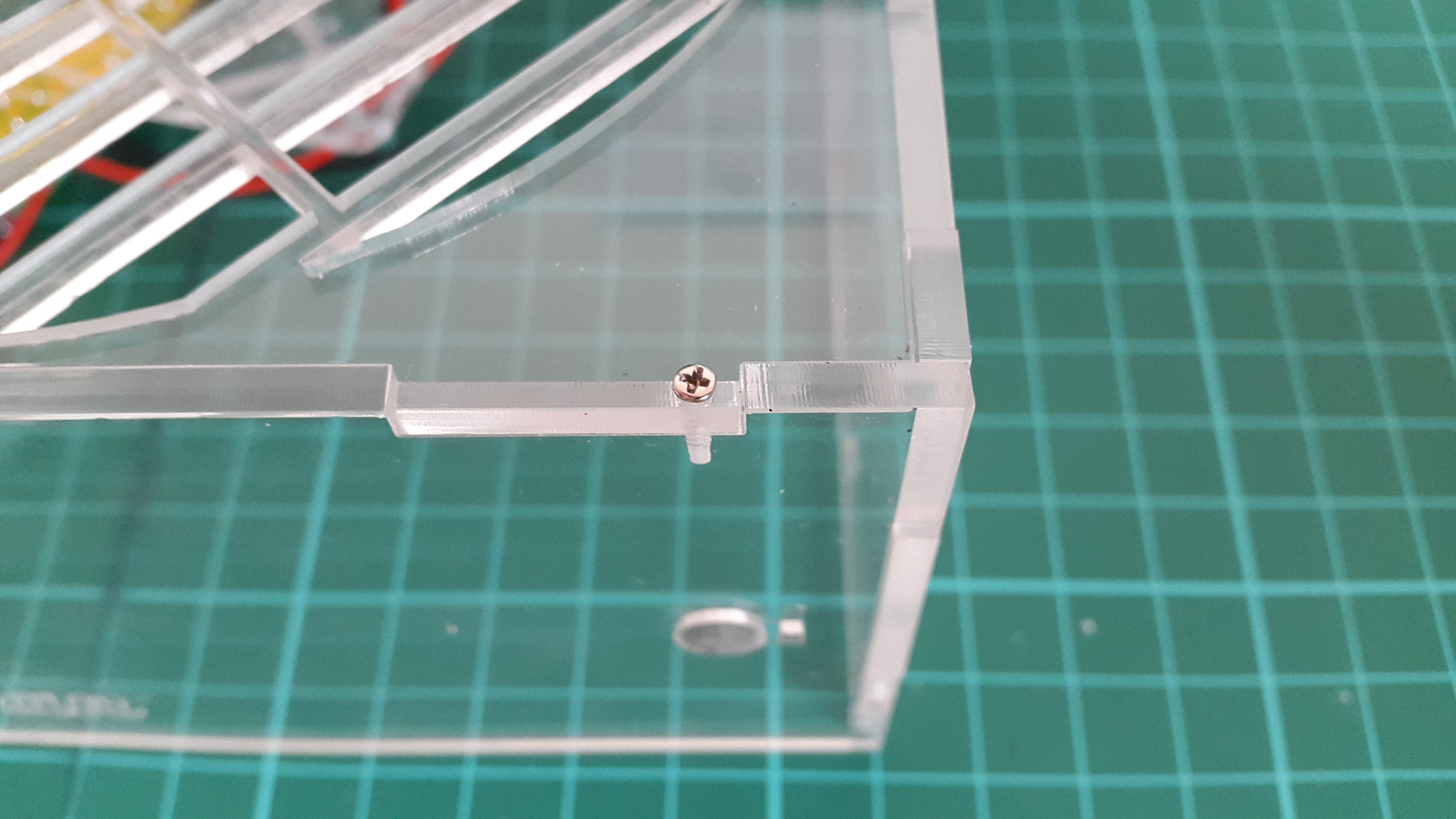
Use the screws provided to tighten the plastic parts together. Do not worry, we have included a few extra screws in case they run from you!
We recommend using the correct Philips screwdriver size #0.
NOTE* Tighten very lightly, the box may crack if you apply a lot of force.
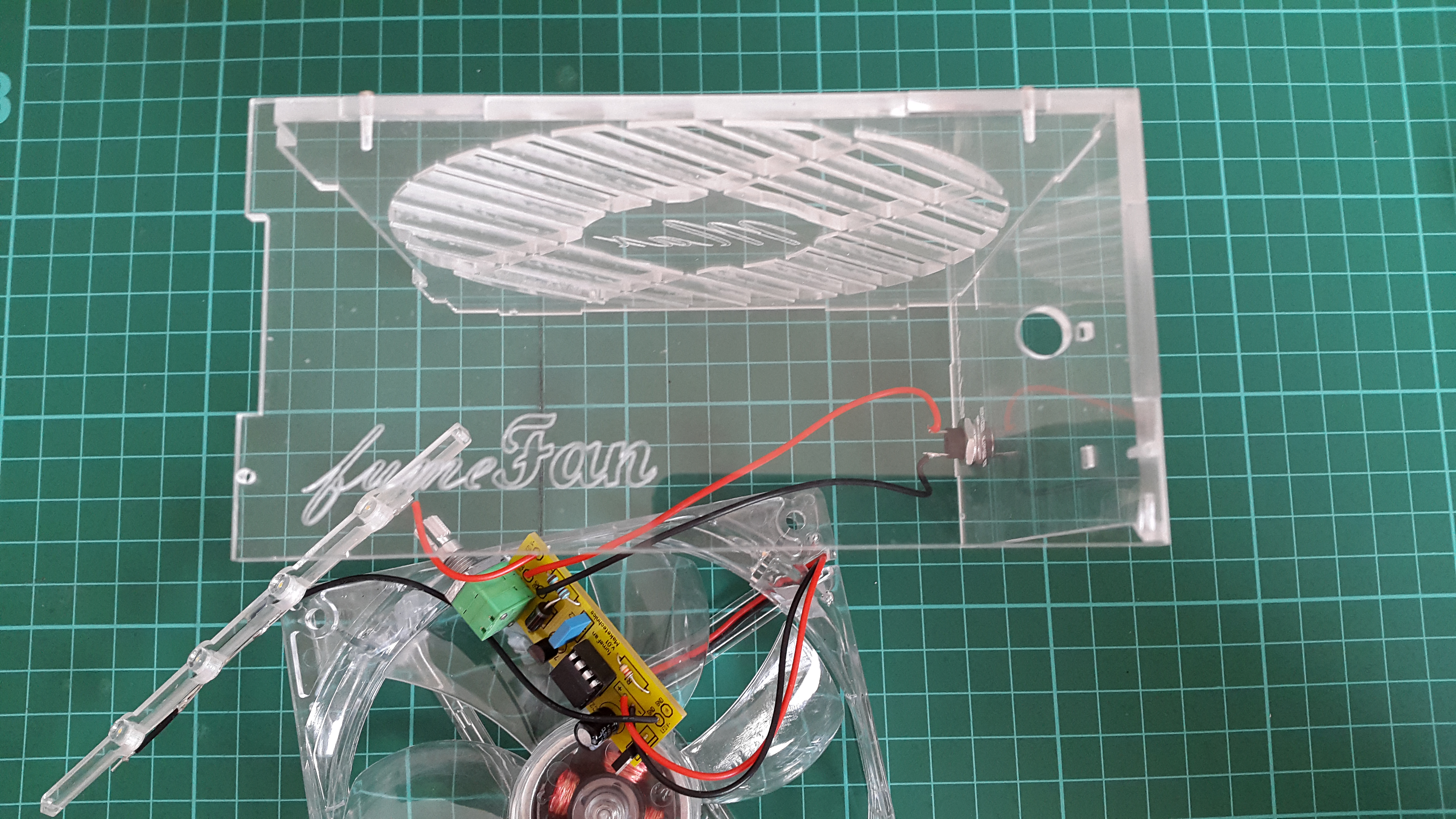
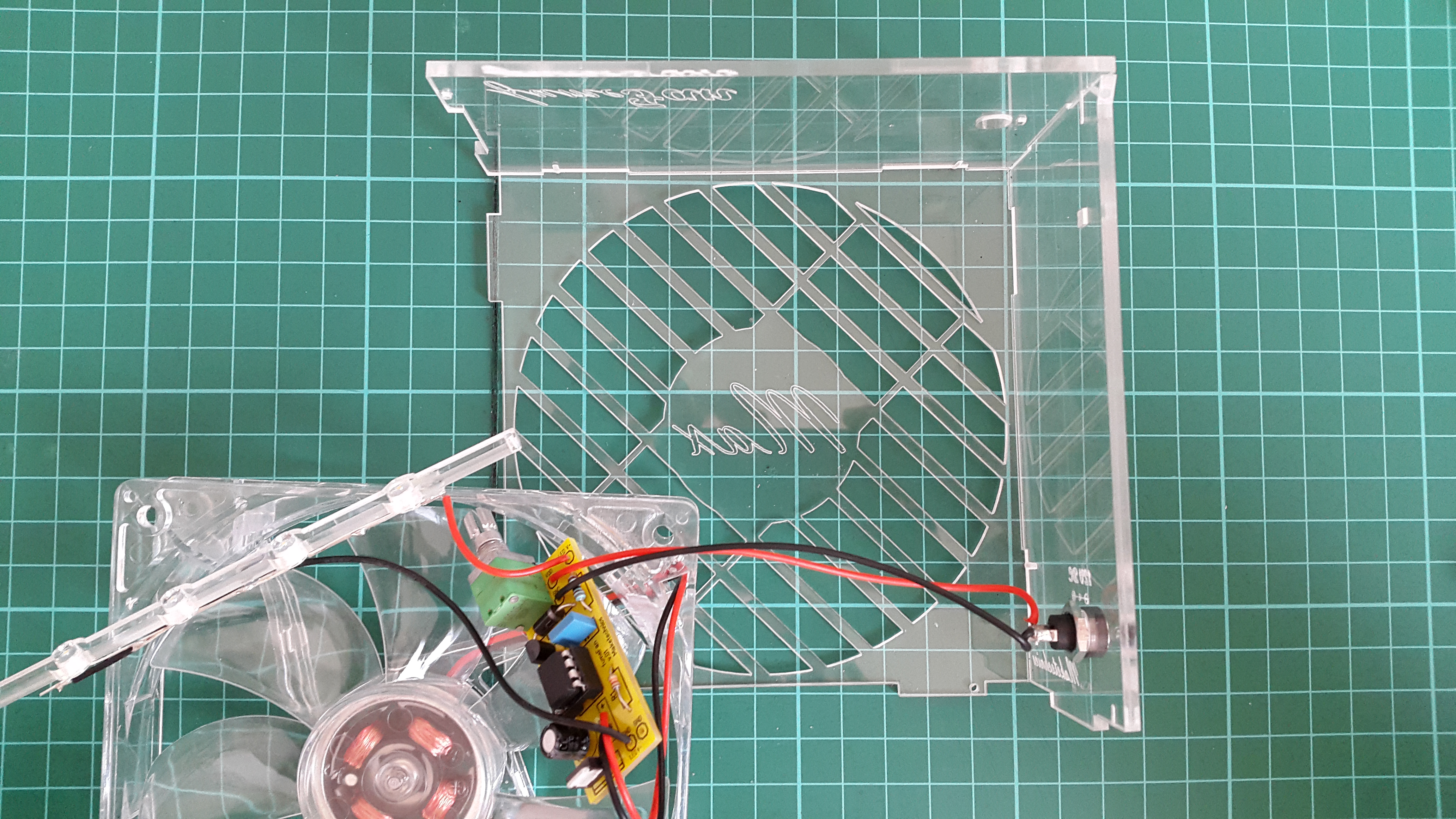
Attach PCB on the Top
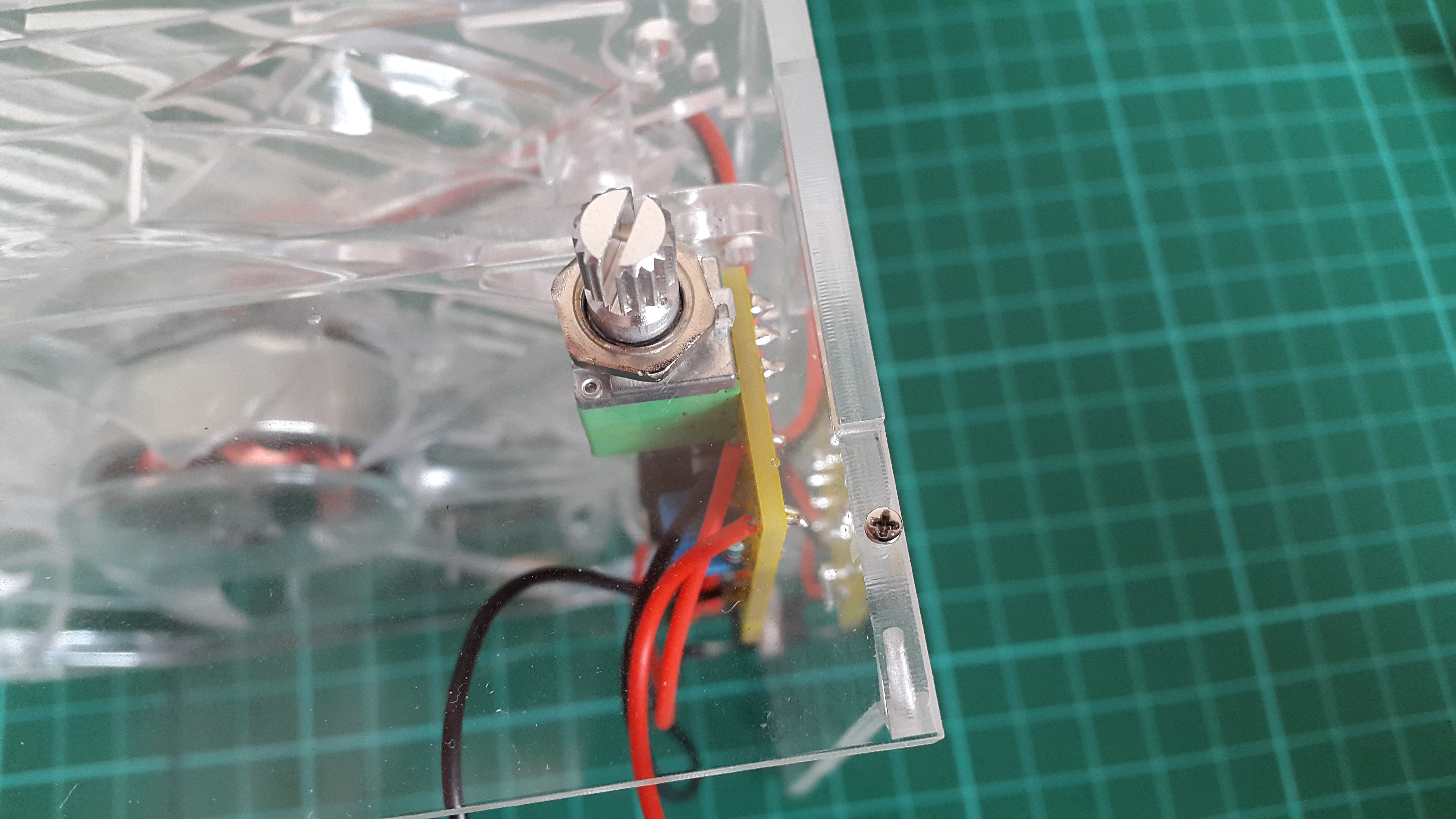
Locate the plastic part that has the "fumeFan" logo on it and insert the potentiometer through the bottom side.
Locate the notch on the potentiometer and the corresponding hole in the acrylic and align them. Tighten with the nut.
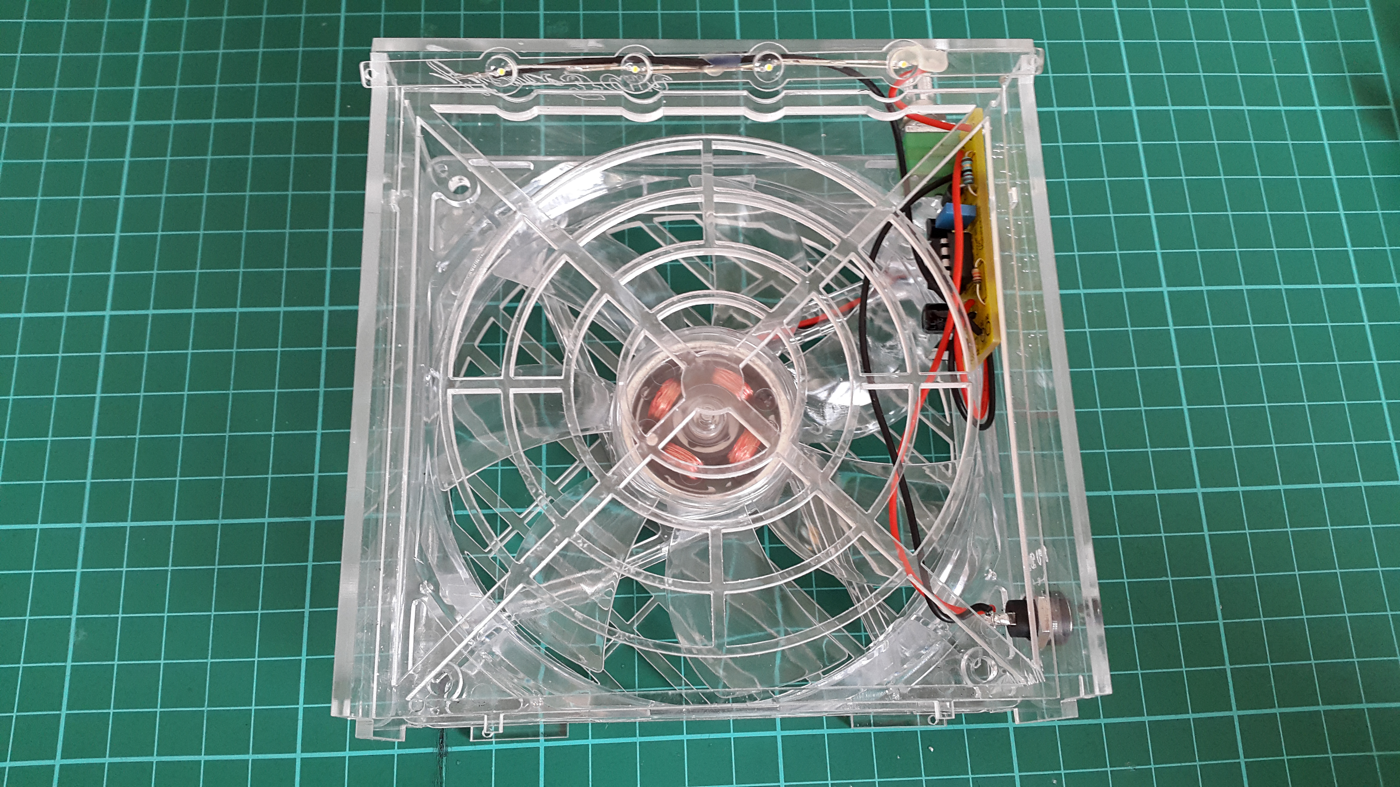
Middle Barrier
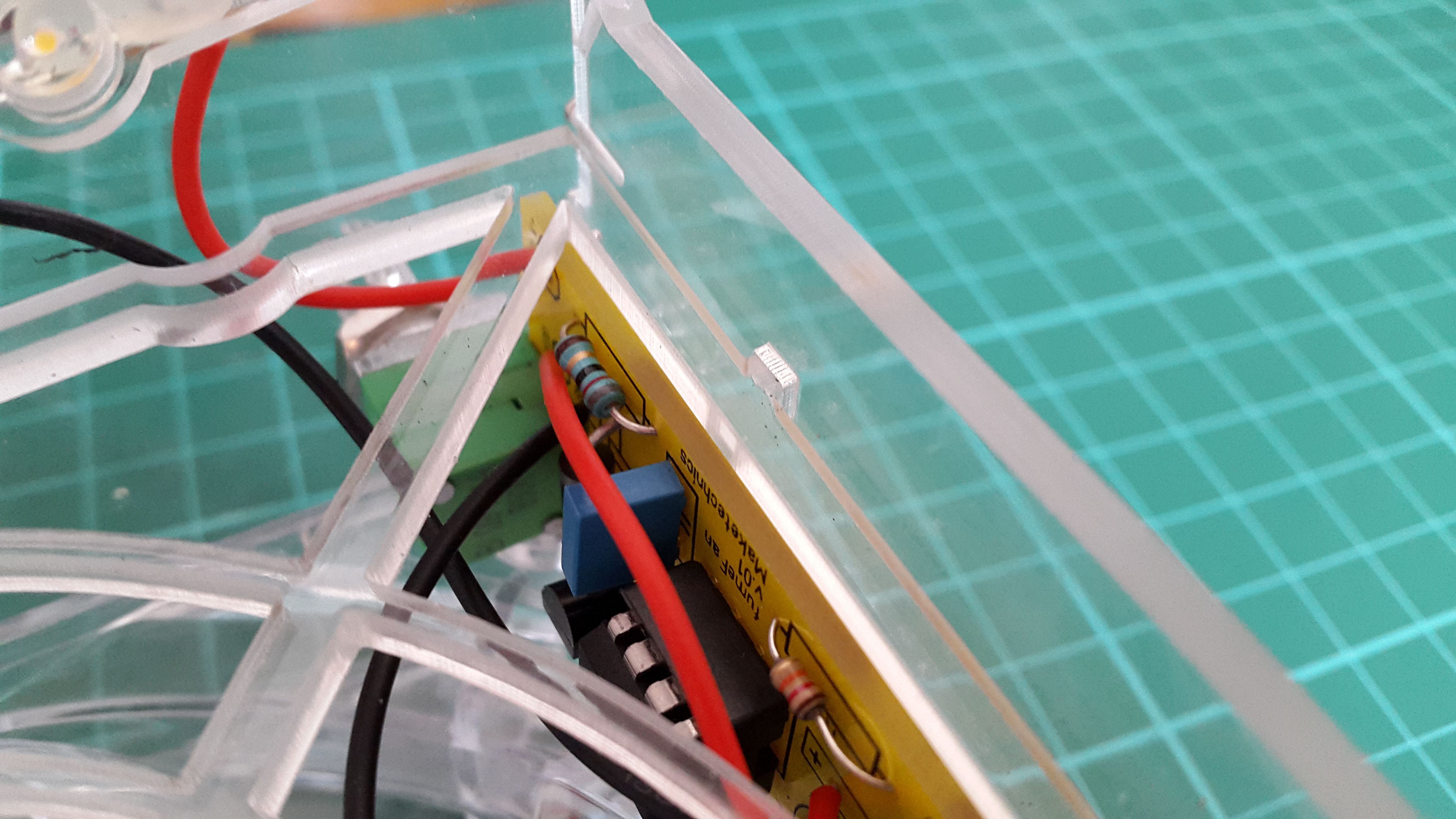
Snap the middle barrier into place. There is only one way that will fit into the box and it will be correct when the two-notch side is on the bottom.
NOTE* The cables may touch the barrier, but in no case should they touch the fan blades. The cable sizes are prepared for a perfect fit. If needed adjust them to stay away from the fan. You can use glue or simply solder the wires pointing towards the barrier. This will keep them away from the fan.
Complete the Box
Attach the other side and the bottom, then fasten with the screws.
NOTE* The white label of the fan should point backwards where the logo is, i.e. you will not see it from this angle.
LEDs Assembly
The LED assembly is held by two screws tightened from the front.
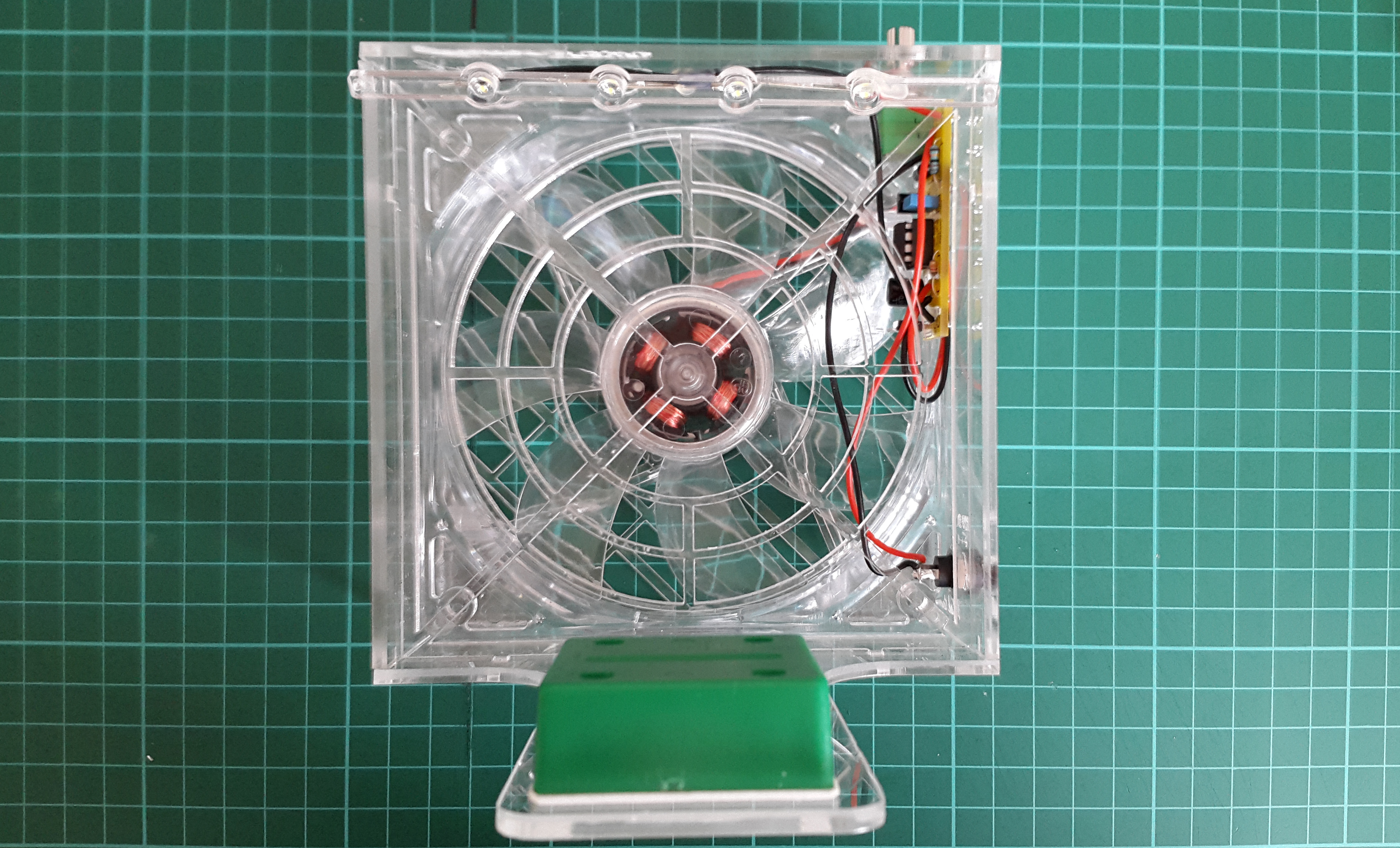
On/Off Pot Cap
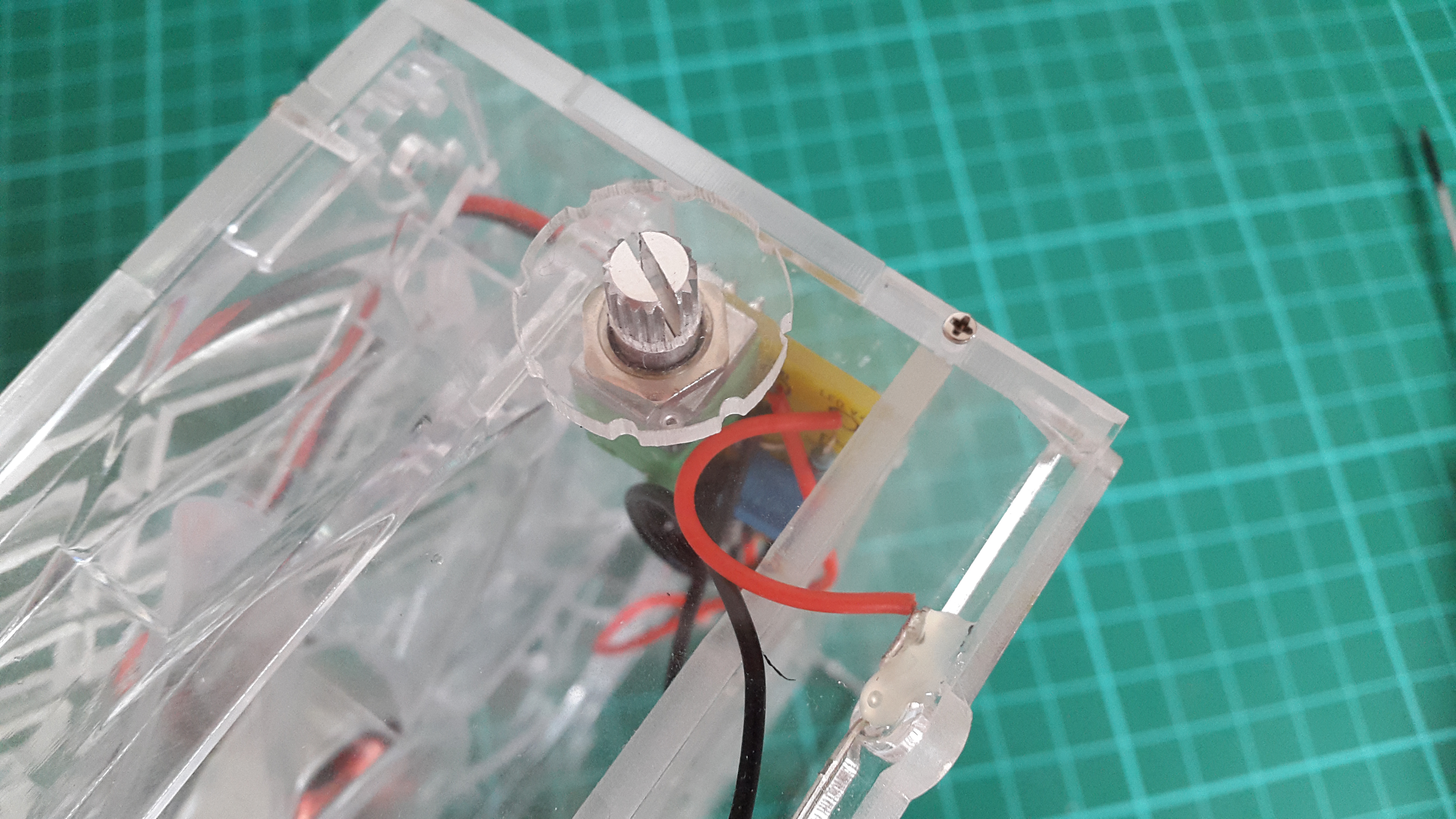
Slide the cap on top of the potentiometer.
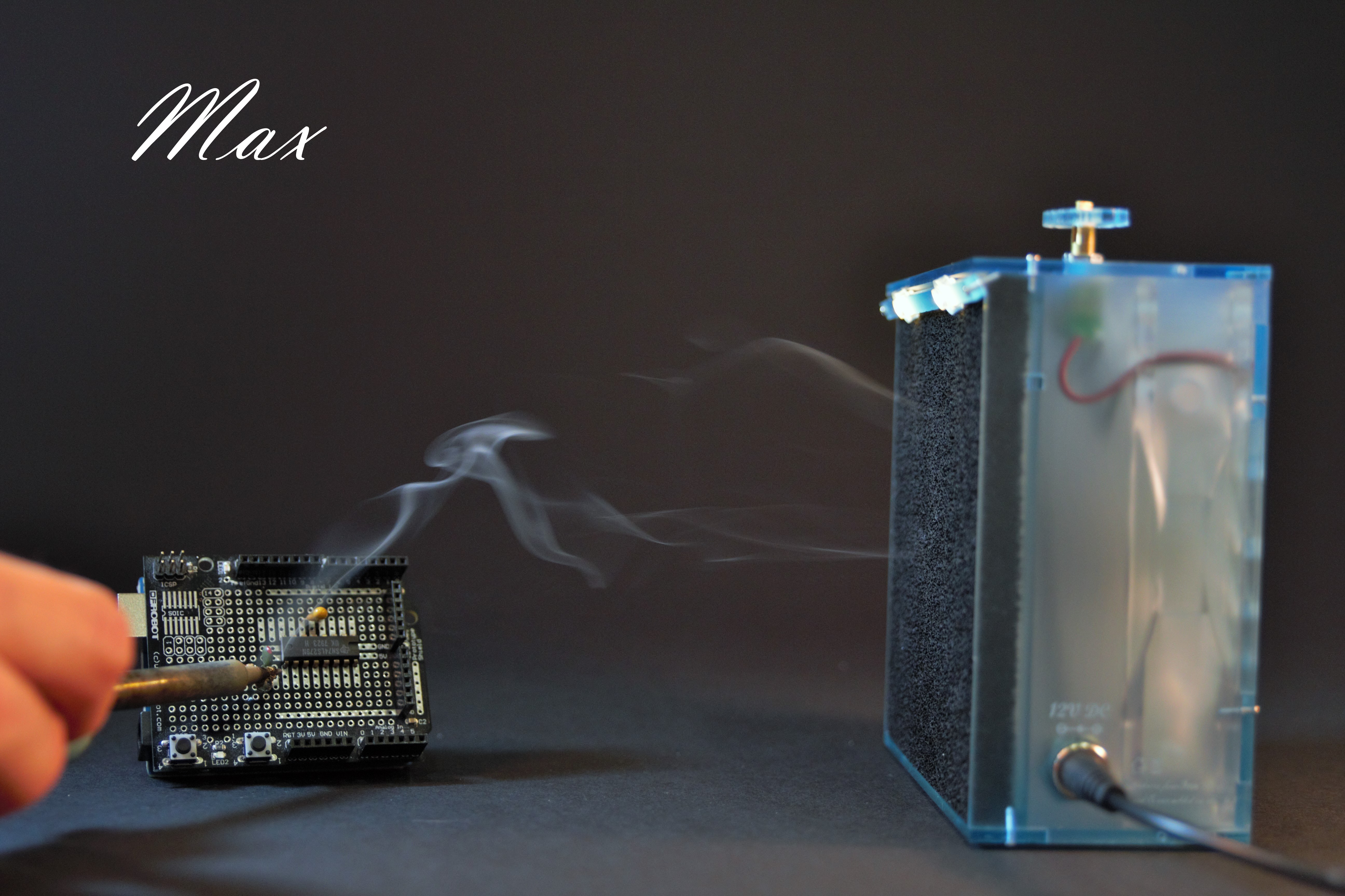
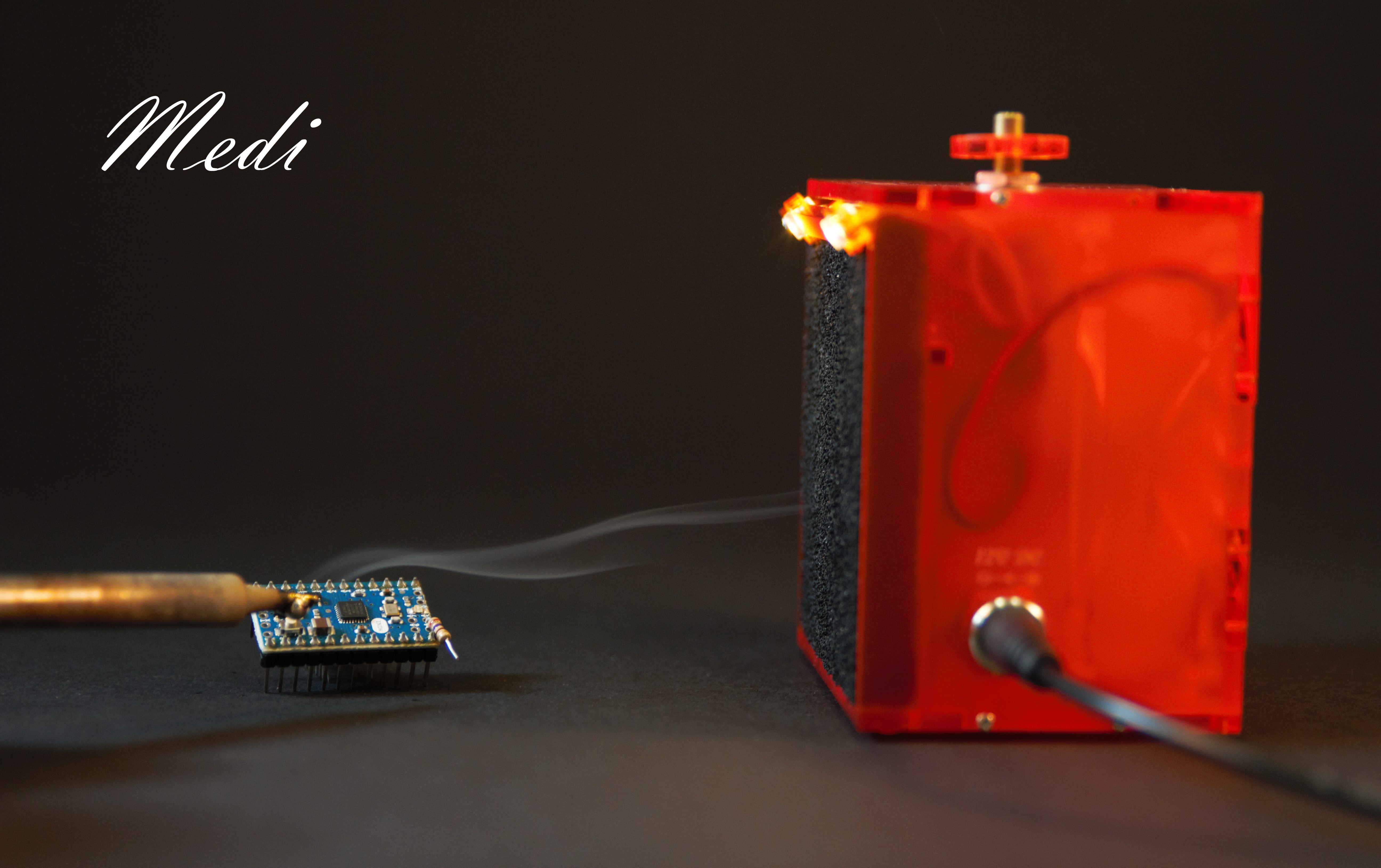
Done! Use It!
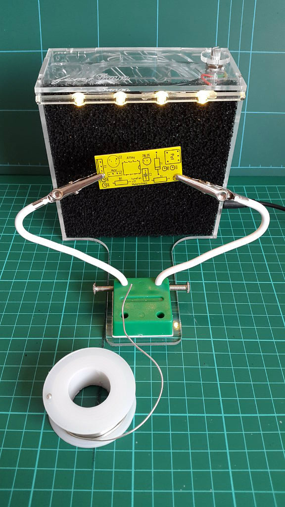
Connect the power cable to a 12V source and turn the potentiometer clockwise. Now you can start soldering and breathe safely!
Troubleshooting
- It won't work ...
- Check the power source supply - It MUST be 12 V DC, any higher voltage will damage the electronics of the fan
- Check steps 2 and 4 - Did you solder correctly?
- Check power supply polarity.
- It blows air the other way around ...
- You installed the fan the other way around, go back to step 5 and flip the fan around.
- It sucks the fumes very weak ...
- Check if something obstructs the air channel ...
- Replace the filter ...
- Have you got enough voltage (12 V) and current (1 A at least) at the power supply?
Still does not work? Give us an email at maketechnics (at) gmail (dot) com and we will help you!