Fully Jointed Catapult
.jpg)
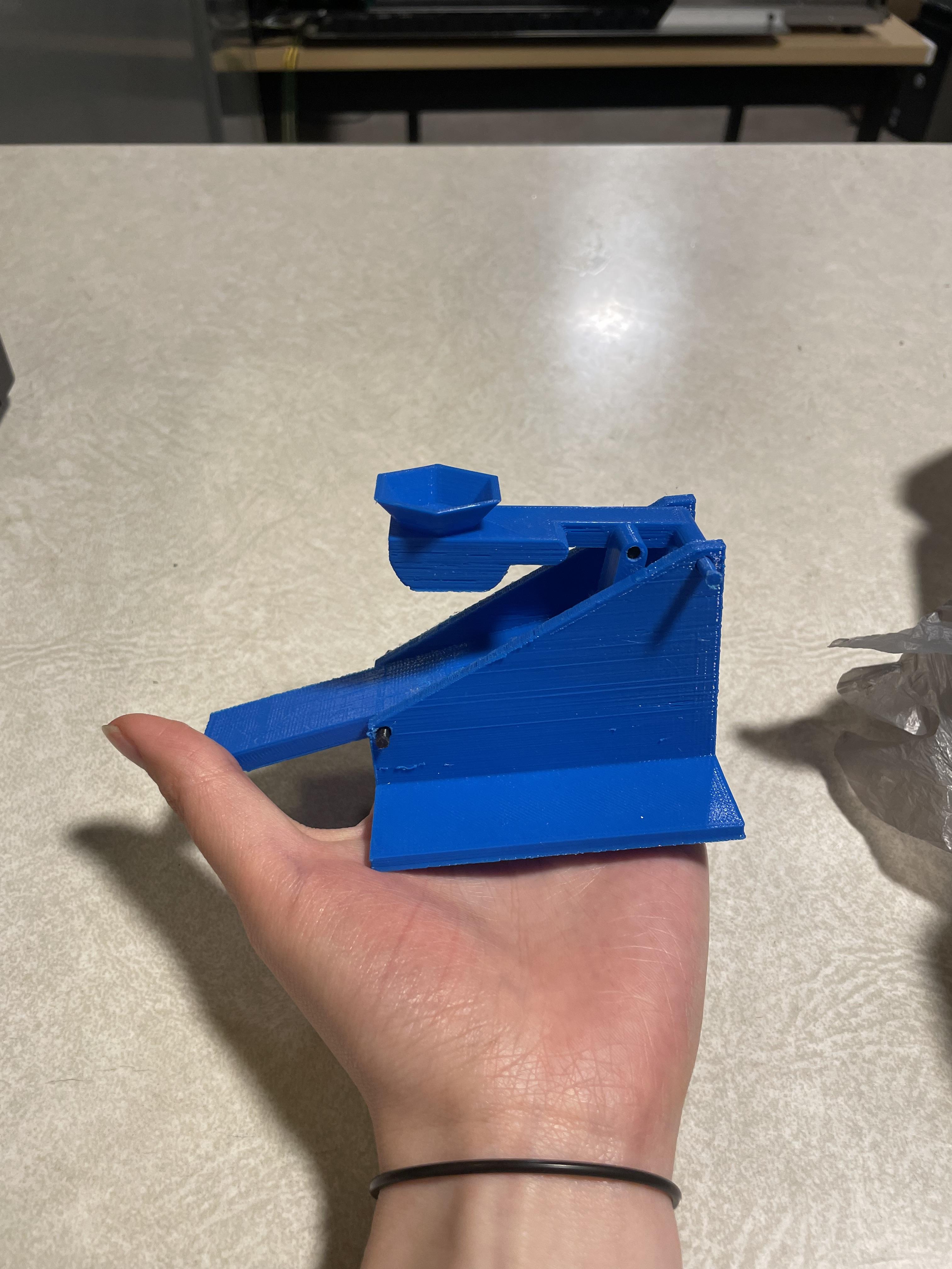
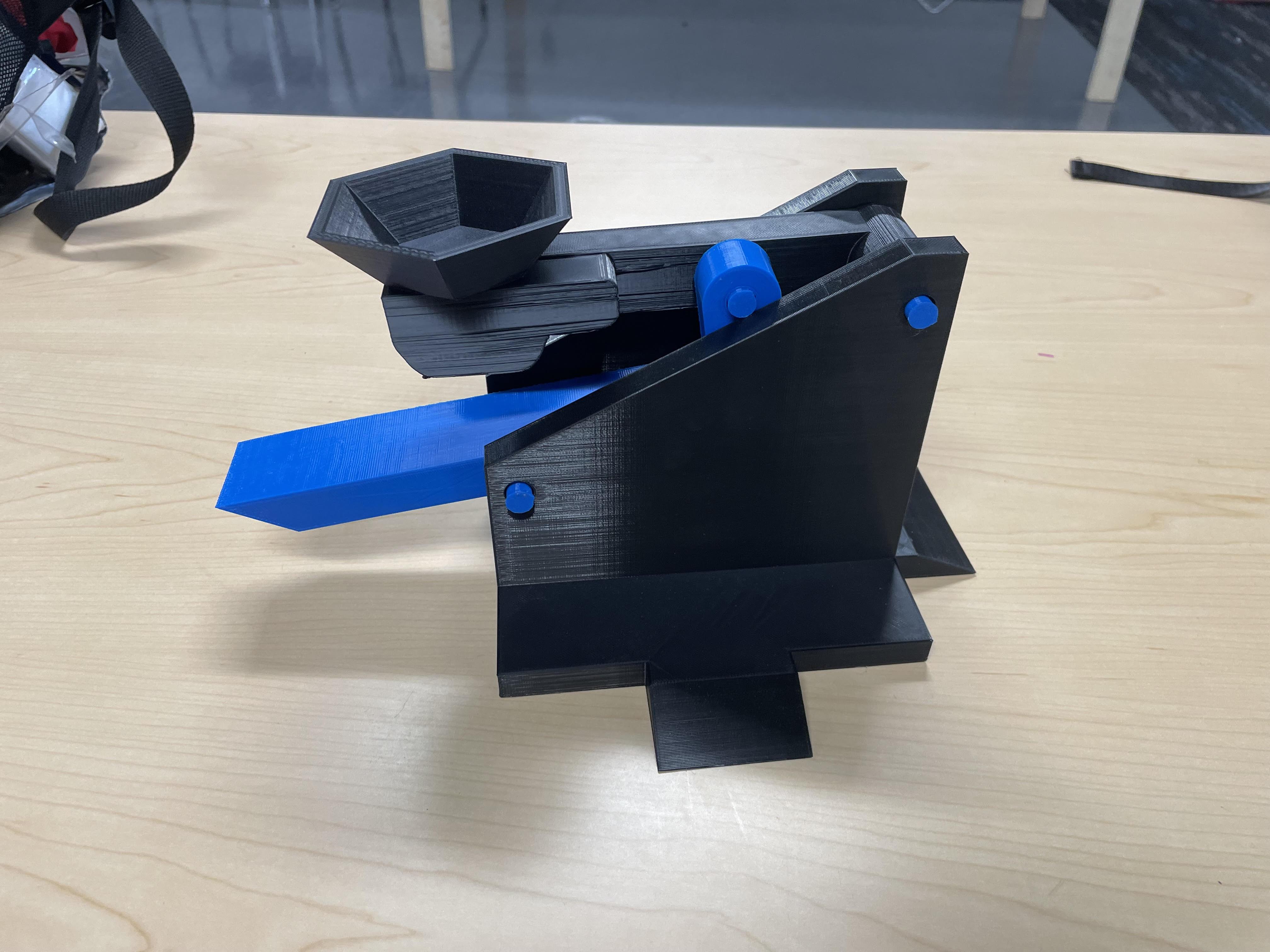
In this instructable, I will be showing you how to create a fully jointed catapult. After seeing how tedious it was to reset a launcher back to its launch position, I wanted to see if there was a more efficient way to reset it into its initial launching position.
After researching, I found that this is not an original project, however, I have made several modifications in terms of designing the overall catapult. It took many revisions, but after many attempts at 3D printing and testing it, the version I ended up with proved to be efficient.
A link I found helpful is provided below:
- 3D Printed Pumpkin Catapult (Shows the basic mechanism of the launcher)
Note*
- Most measurements will not be 100% accurate due to rounding.
Supplies
.jpg)
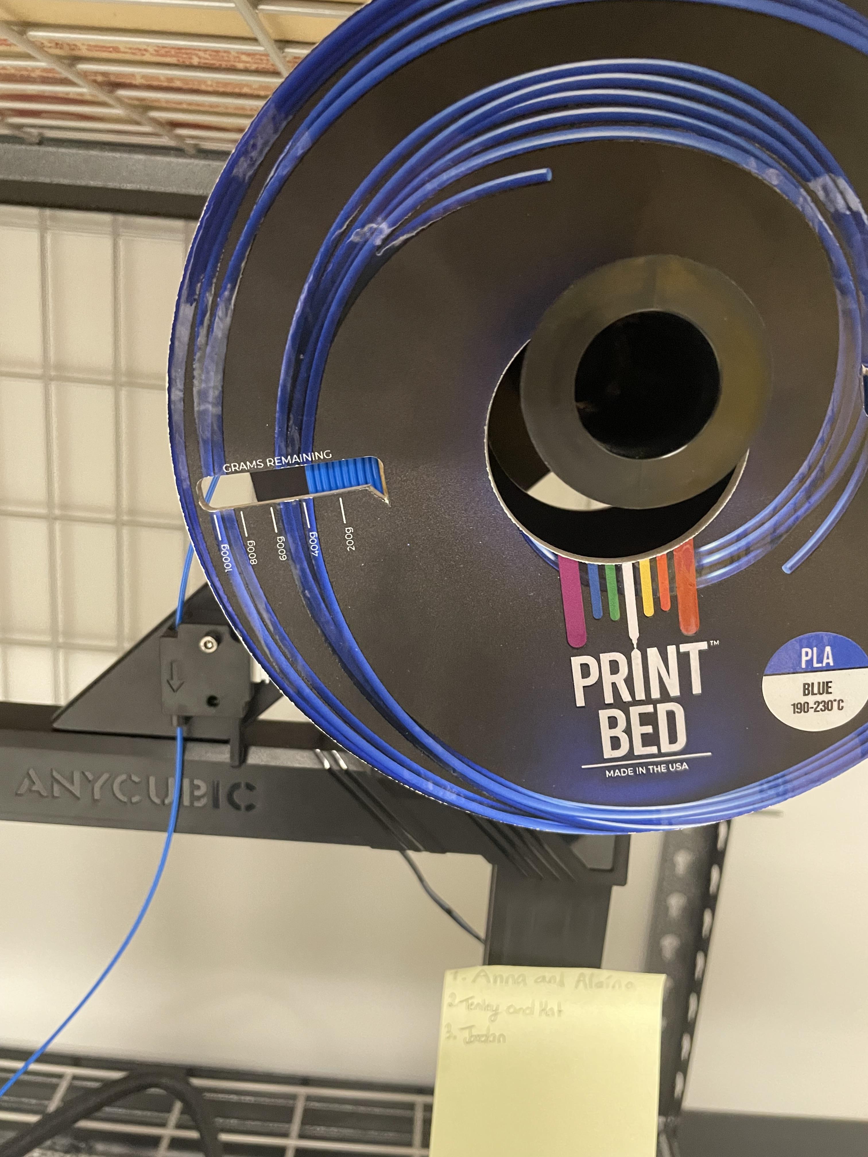

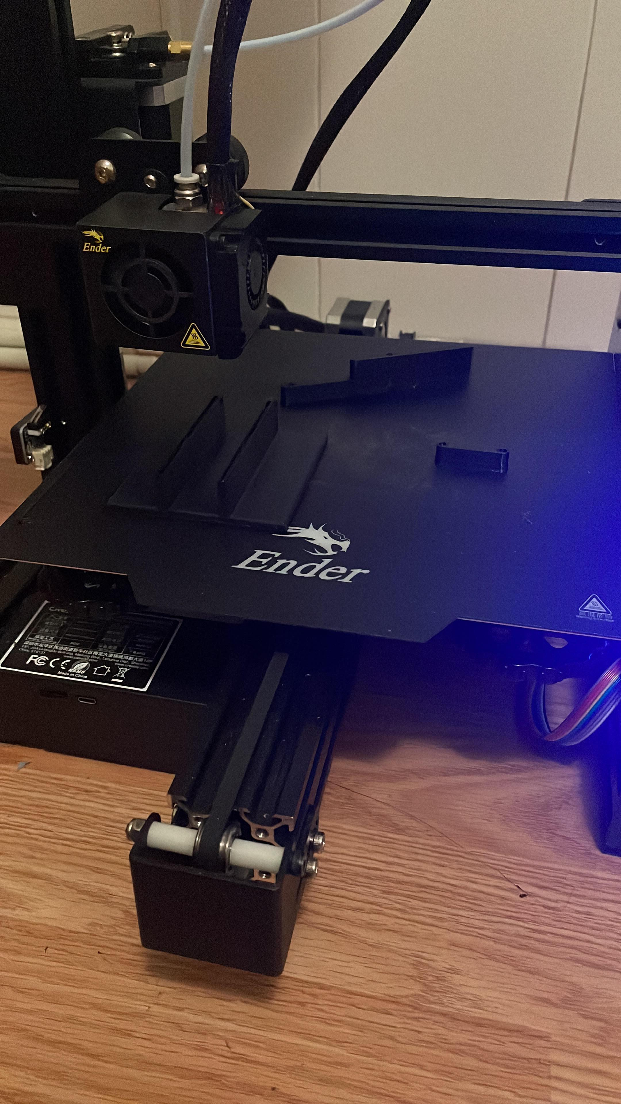
For supplies I used a 3D printer, PLA filament, a slicing software called Cura, and a website called Onshape, which is a CAD platform used in order to make this fully jointed catapult.
Cost:
3D Printer - $170~
PLA filament - One roll of 1000g usually costs around $25.00 (Based on the weight of the catapult I made, it costs around $10.45
Onshape software - Free online :)
Cura - Free to download :)
Onshape
.jpg)
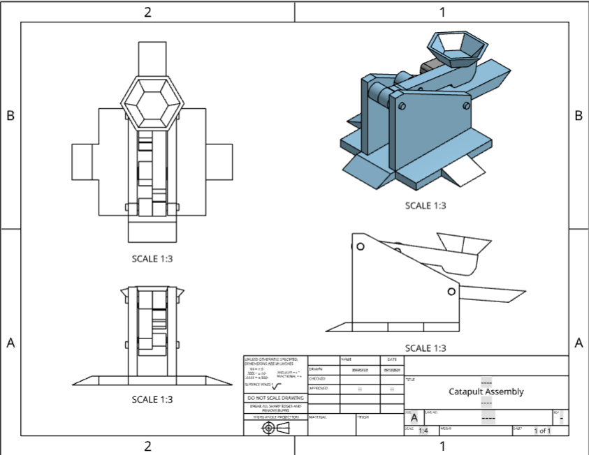
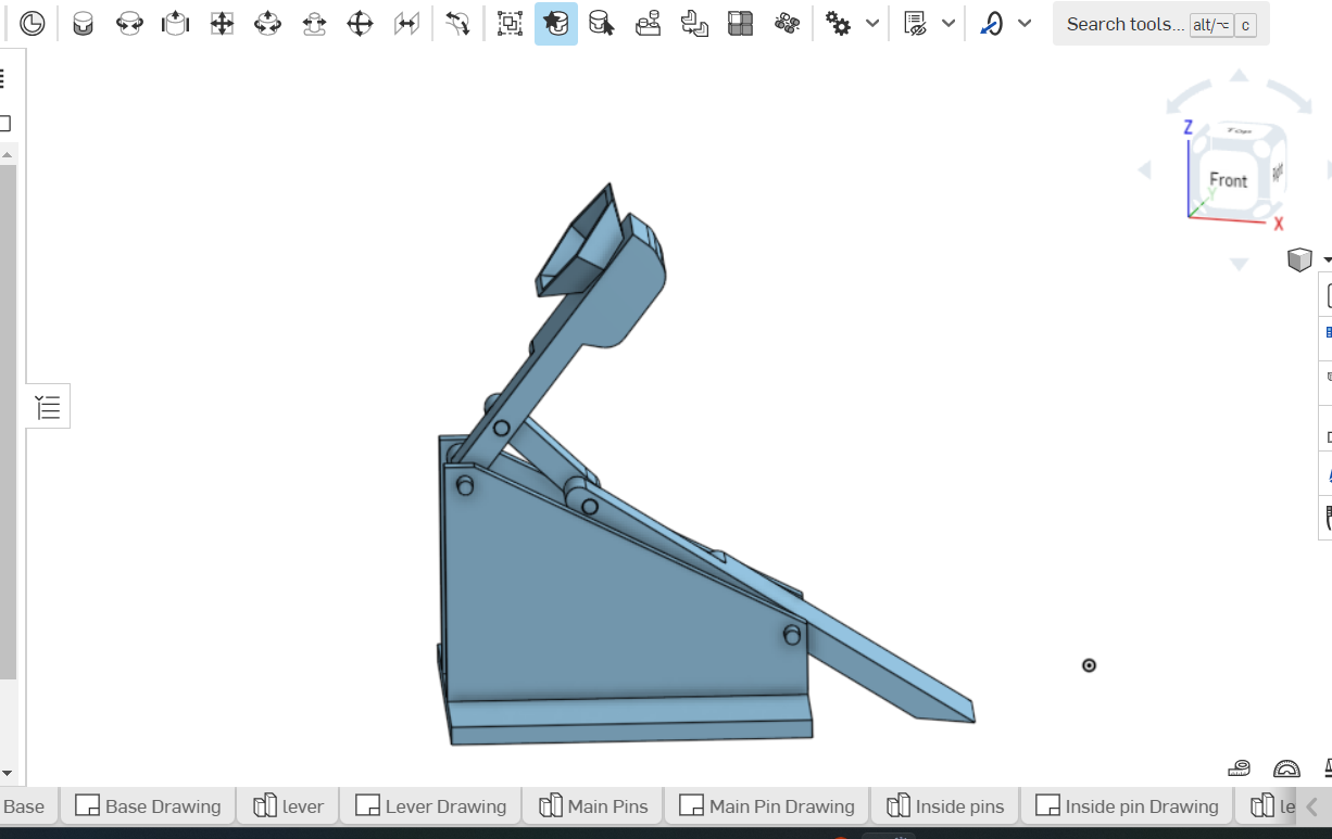
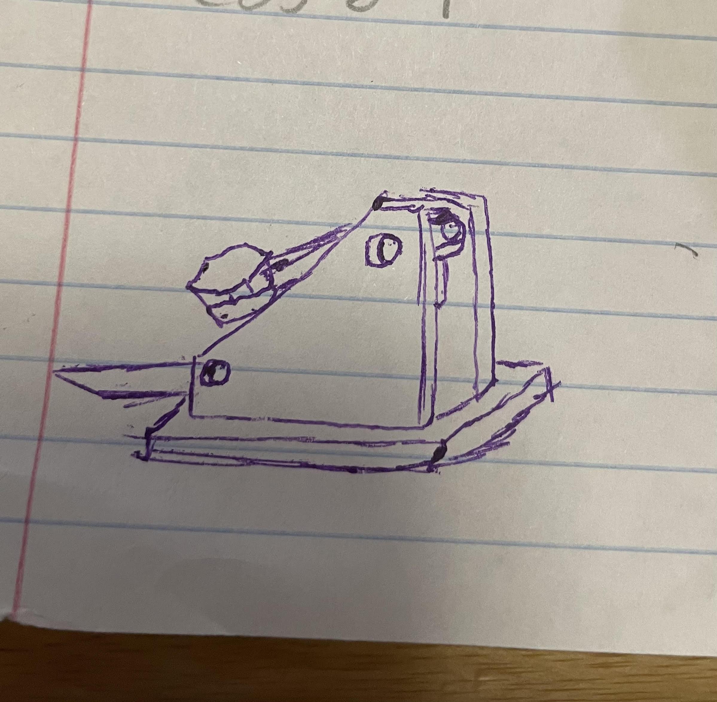
As a visual learner, I already had a picture of how I wanted to design this catapult, so after a quick sketch I directly went on to Onshape and started the online sketch.
***If you are new to OnShape, be aware that each step labelled Part # is a different part studio created
Creating the Base
.jpg)
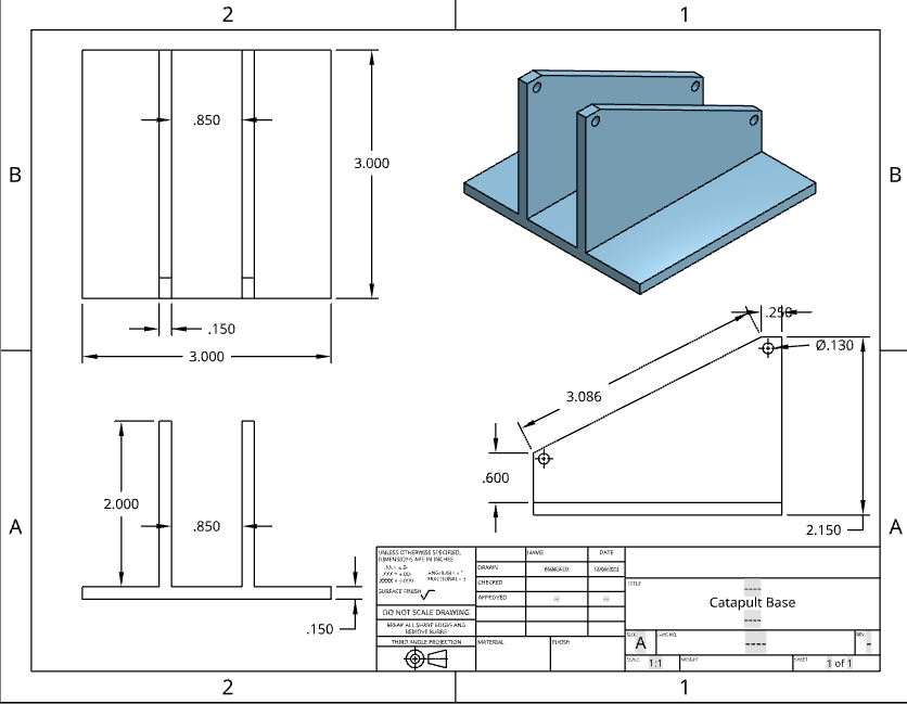
Part 1 - For the sketch of the base, make a 3x3 in. square and extrude it to 0.25 inches.
Part 2 - Using the top view, put a 0.9 inch mark at the left and right sides of the square, and put a rectangle measuring 3x0.2 in. across and extrude it to 2.5 inches.
Part 3 - From the left view sketch a vertical line 1.106 inches long that is perpendicular to the parallel lines made in part 2. Again, this must be done from LEFT view. From there draw a line from the previous point (Point A) to the top (Point B) and dimension it to 3 inches. Now in order to cut this part out, connect point B to the left corner (Point C) and down to Point A to form a triangle. Now to remove this triangle, click the extrude icon and click the "remove" option (3rd from the left under "Solid"). From here type in 3 in. in the "Depth" section underneath "Remove".
Part 4 - Stay on left view and on the top right corner of the structure, draw a line 0.23 in. to the left (Point D) and another line down from the top right corner measuring 0.36 in. (Point E). From Point D, draw a line 0.36 in. down and another line 0.23 in. to the left from Point E. Click on the "Center point circle" function and click on where the two lines from point D and E intersect and input the diameter of 0.195 in. Once drawn, the lines can be trimmed with only the circle remaining. For the second circle, go to the bottom left corner of the structure and draw a line 0.21 in. to the right (Point F) and another line up from the bottom left corner measuring 1.12 in. (Point G). From Point F, draw a line 1.12 in. up and another line 0.21 in. to the right from Point G. At the point where they intersect, click on "Center point circle" and input the diameter of 0.195 in. Again, make sure to trim the lines and only have the circle remaining. Finally, click the "extrude" icon and remove the two circle by clicking each one and give it a depth of 3 in.
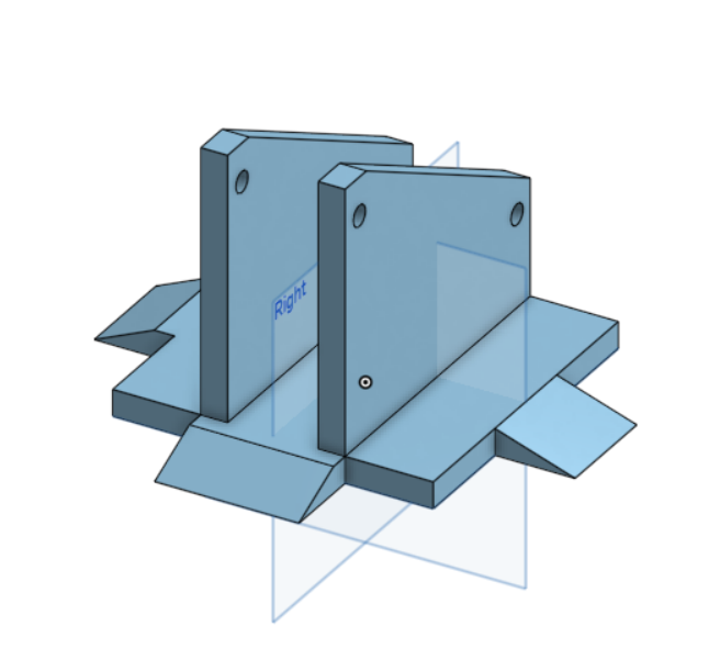
Part 5 - Use the "Transform" function and click on the overall base. Below the "Entities to transform or copy" choose the scale option from the drop down box and scale it uniformly to 2. For "Point or mate connector" click on the vertex of origin. This will enlarge the structure.
Part 6 - For the flaps on the side of the base, view from right plane and sketch a rectangle using the "Corner rectangle" function from the bottom of the structure that is 2 inches wide from the center (one inch wide left and right from the center) and 0.5 in. high where it will meet up with the top of the 3x3 made in Part 1. From here use the "Extrude" function to add and input a depth of 1.5 in.
Part 7 - Change the right plane view to front view and use the "Corner rectangle" function to trace (sketch) the previous extrude. Proceed to draw a diagonal line from the top left of this rectangle to the bottom right. Again to "remove" the piece we want, trim the left and bottom sides of the rectangle and use the "Extrude" function to remove the piece at a depth of 2 inches.
Part 8 - Repeat Part 7 twice. Once for the left view and once for the front view.
Levers and Pins
.jpg)
Lever
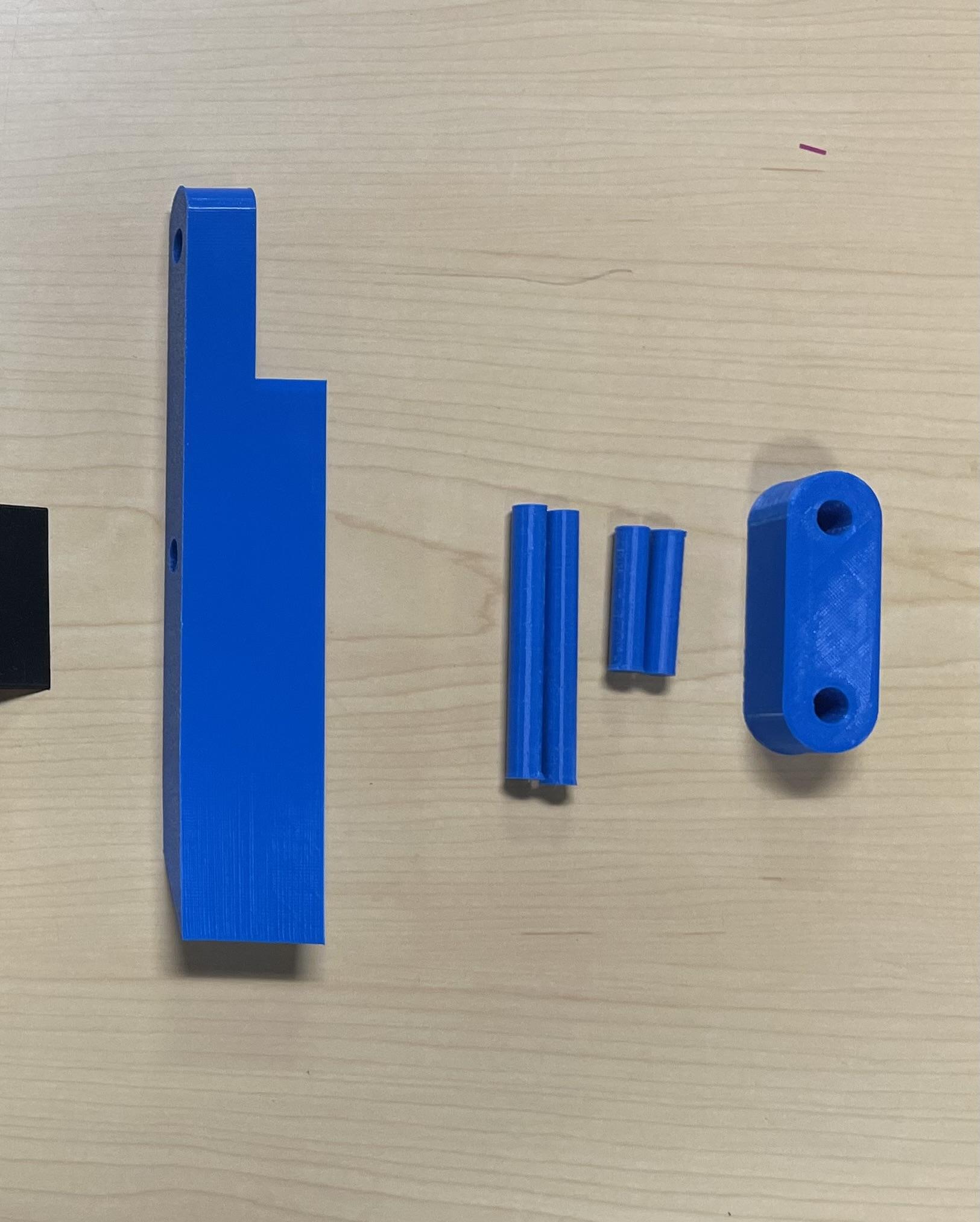
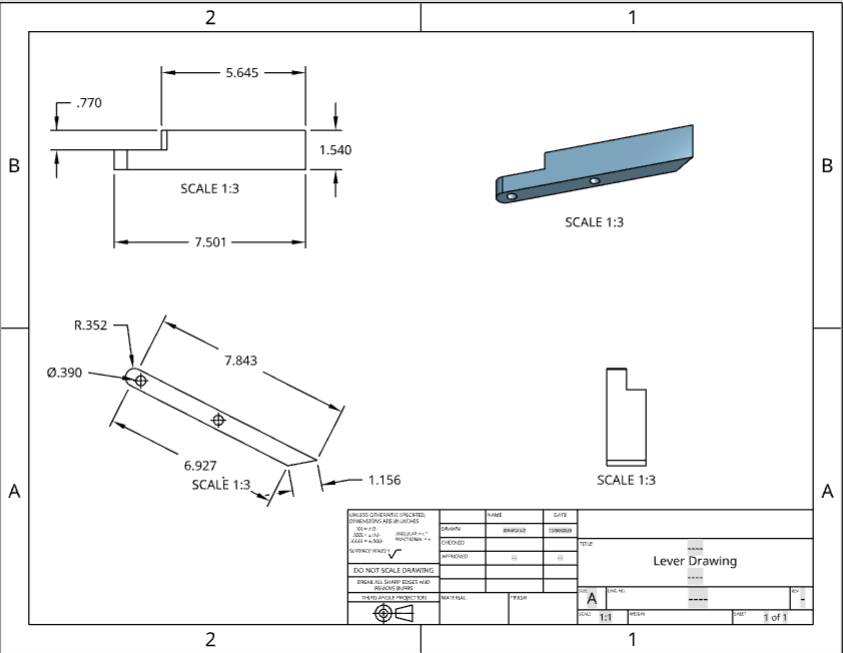
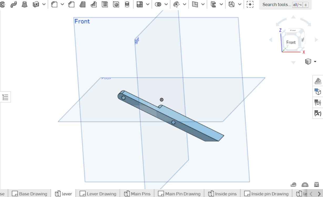
Part 1 - Sketch a horizontal line (Line 1) that is 7.3 inches long and add a line (Line 2) on its right point (Point A) that is 1.16 inches and has an angle of 142.5 degrees pointing upwards from the initial line drawn. From the left point of the sketch, which is also the left end of the initial line (Point B), draw a perpendicular line (Line 3) measuring 0.70 in. facing upwards. Add another line (Line 4) to connect the endpoints of lines 2 and 3 which should measure out to be around 8.2 in. After all these steps are completed, use the "extrude" function and extrude the sketch at a depth of 1.54 in.
Part 2 - On part 1's front view, sketch a line (Line 5) measuring 0.70 in. to the right from Point B on Line 1. After this, find the middle of line 5 and add a perpendicular line (Line 6) that reaches line 4. Now at line 6, find its center point use the "Center point circle" function and create a circle at that point that will touch with the center of line 3 measuring a radius of 0.352 in. Use the trim tool to cut out the lines within the circle and the right half of the circle. Next, use the "extrude" function to Remove the corners on the top and bottom left of this now semi circle.
Part 3 - At the center of this semi circle, use the "Center point circle" function and create a circle at that point measuring a diameter of 0.39 in. From the center of this circle, sketch a horizontal line measuring 3.41 in. and create another circle at this endpoint with the same diameter of 0.39 in. Make sure to trim any lines created in part 3 and leave only the two circle remaining. Extrude to remove these two circles at a depth of 1.54 in.
Part 4 - Change the front plane view to back plane view and draw a horizontal line from the middle of the curve on the right end of the structure to 2.09 in. to the left. From this endpoint (Point C) draw another horizontal line (Line 7) in the same direction but instead at a length of 0.70 in. At the endpoint of line 7 create a circle with a diameter of 0.70 in. and trim the left half of the circle. After this step, trace over the outline of the structure on the right of the semi circle just created and make sure to trim the diameter of the semi circle and ALL of the horizontal lines made (not including the hole extruded). Now extrude the outline and remove it at a depth of 0.77
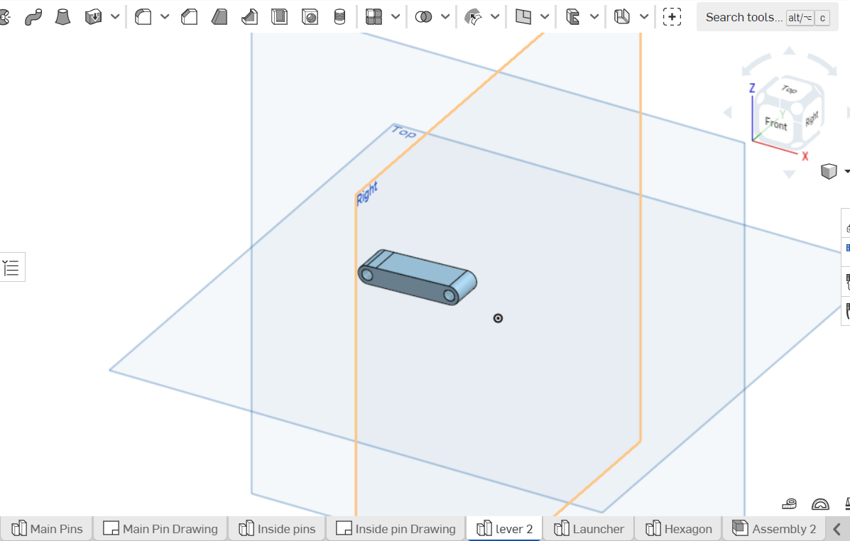
Lever 2
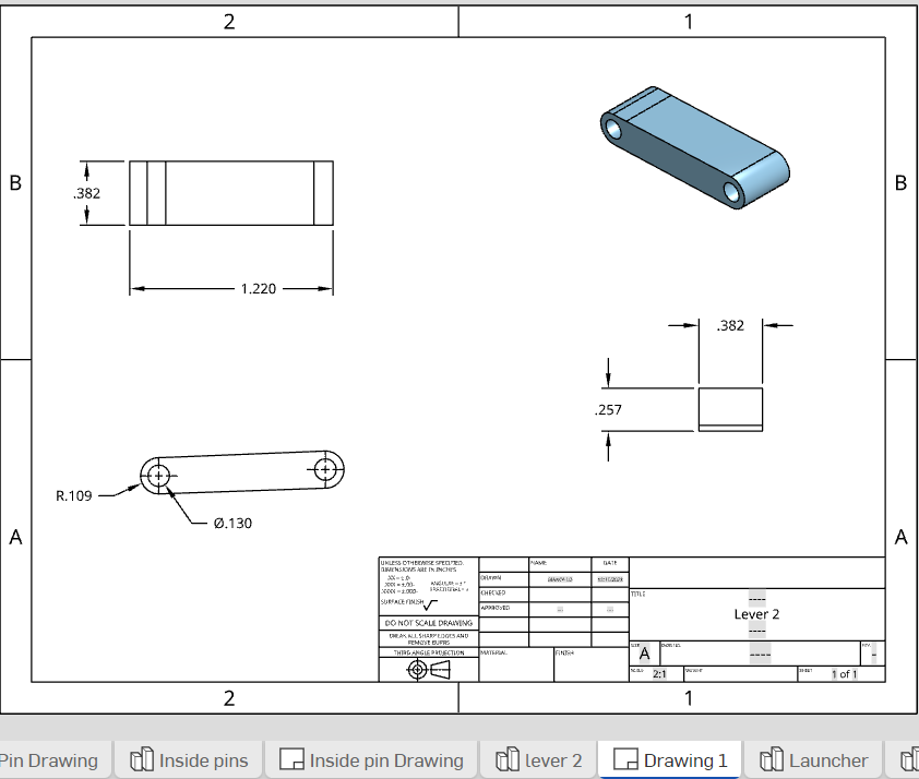
Part 1 - Sketch a corner rectangle measuring 1 in. on the top and bottom and 0.51 in. on the left and right sides of the rectangle.
Part 2 - Find the center of the left line and create a circle at the point of this center that reaches until the corner of either the top or bottom left corner of the rectangle. Repeat this step for the right side. As mentioned previously, measurements are not 100% accurate therefore the directions appear vague for general use. The diameter for both circles should be around 0.51 in. Trim the lines inside of the circles and create a smaller circle inside each with a diameter of 0.195 in. at the center of these circles, Proceed to trim the halves of the 0.51 diameter circles that are facing inwards towards the rectangle.
Part 3 - Extrude the part at a depth of 0.385 in. and use the "Transform" function to scale the part uniformly by 2.
Main Pins
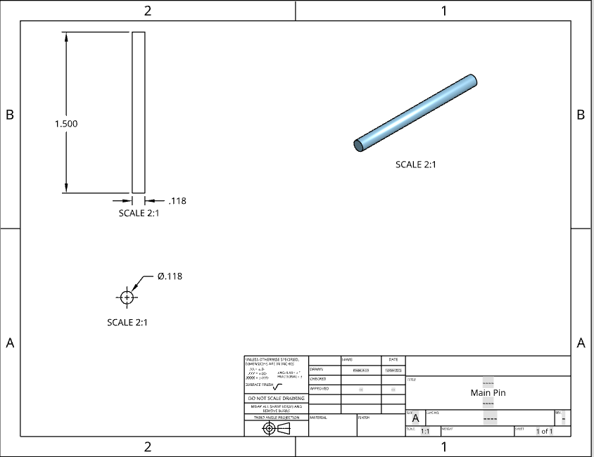
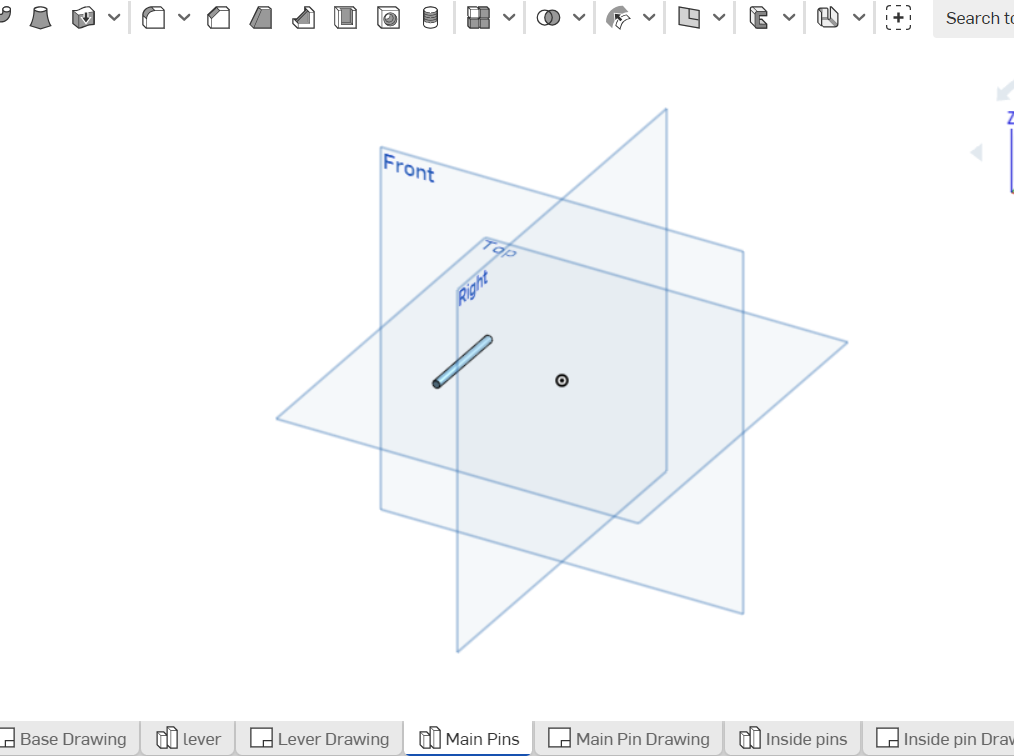
Part 1 - Sketch a circle with a diameter of 0.354 in. and extrude the sketch to a depth of 3 inches.
Inside pins
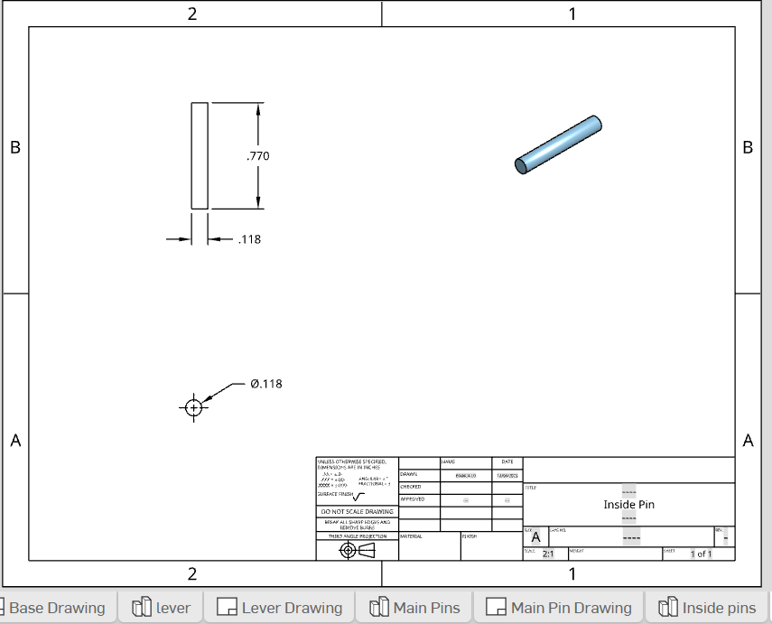
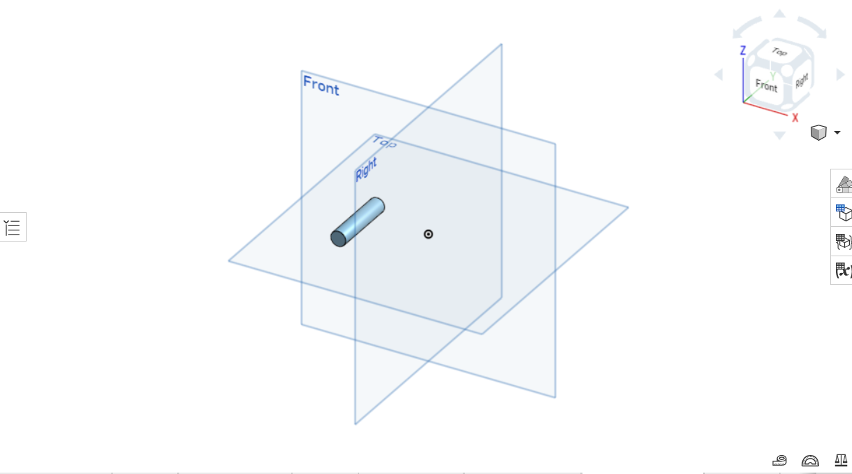
Part 1 - Sketch a circle with a diameter of 0.354 in. and extrude the sketch to a depth of 1.59 inches.
Launcher
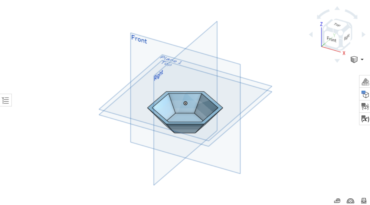
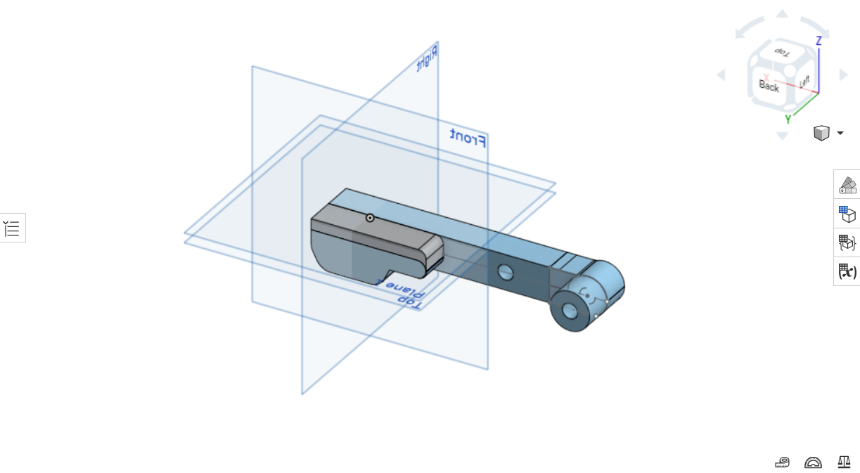
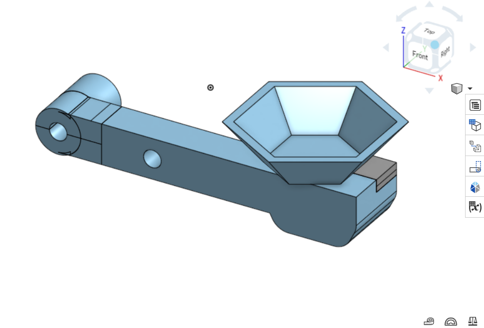
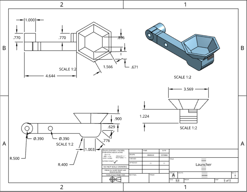
Overall, the launcher was the most time consuming part of this project because it had to be split into 2 parts.
Launcher
Part 1 - On the front plane, sketch a corner rectangle with a horizontal width of 7.1 in. and a height of 0.9 in. On the bottom left corner (Point A) of the rectangle sketch a line (Line 1) measuring 0.9 in. to the right of point A on the bottom line of the rectangle. Now at the center of line 1, sketch another line (Line 2) that is perpendicular and pointing upwards until it reaches the top line. At the center of line 2, sketch a circle that reaches to the center of the left side of the rectangle. After this step, be sure to trim the inner half of the circle facing the inside of the rectangle and also the top and bottom left corners. Now to the right of the structure, sketch a corner rectangle (Rectangle 2) from the bottom right point (Point B) to 1.91 in. to the left of point B on the bottom line of the rectangle that measures a width of 1.91 in. and a height of 0.33 in. Make sure to trim the top line of rectangle 2 to make the extrusion easier for later (For style, you can use the fillet function to round out the bottom corners of rectangle 2). At this point, use the "Extrude" function to extrude the structure to a depth of 1.54 in.
Part 2 - Change the front plane view to back plane view, and at the center of the semi circle on the right end, use the "Center point circle" function and create a circle at that point measuring a diameter of 0.39 in. From the center of this circle, sketch a horizontal line measuring 2.1 in. and create another circle at this endpoint with the same diameter of 0.39 in. Make sure to trim Extrude to remove these two circles at a depth of 1.54 in.
Part 3 - Still using the back plane view, draw a horizontal line from the middle of the curve on the right end of the structure to 4.2 in. to the left. From this endpoint (Point C) draw another horizontal line (Line 7) in the same direction but instead at a length of 0.9 in. At the endpoint of line 7 create a circle with a diameter of 0.90 in. and trim the left half of the circle. After this step, trace over the outline of the structure on the right of the semi circle just created and make sure to trim the diameter of the semi circle and ALL of the horizontal lines made in part 3 (not including the circles extruded in part 2). Now extrude the outline and remove it at a depth of 0.77 in.
Hexagon
Part 1 - Sketch a hexagon (Hexagon 1) on top view using the "Inscribed polygon" function measuring 0.33 in. on each side. Next use the "Plane" function and click on the top plane to fill in the function's entity. Make sure the drop down box underneath "Entities" says "Offset" and input an offset distance of 0.3 in.
Part 2 - Using the sketch from part 1, sketch another hexagon (Hexagon 2) using the same center point of hexagon 1. The measurement for each side of hexagon 2 is 0.595 in. on each side.
Part 3 - Use the "Loft" tool and check to see that the settings are set up on "Solid" and then to "New", which can be found underneath "Solid". For the "Profiles" section, input the face of the sketch of hexagon 1 FIRST and hexagon 2 SECOND.
Part 4 - Locate the "Shell" icon and input the face of the loft made in part 3 for "Faces to remove" and input a shell thickness of 0.05 in.
Part 5 - Use the "Transform" function and click on the overall structure. For "Entities to transform or copy", click on the center of the hexagon structure for "Mate connector" and anywhere on the hexagon structure to enlarge it. Below the "Entities to transform or copy" choose the scale option from the drop down box and scale it uniformly to 3. For "Point or mate connector" click on the vertex of origin.
Part 6 - Create an assembly and insert both the hexagon and launcher. Use the "Fastened mate" function to attach the bottom of the hexagon to the top side of the launcher.
Catapult Assembly
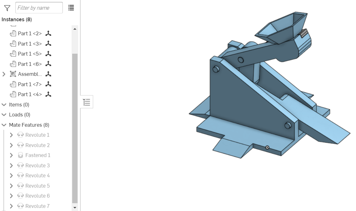
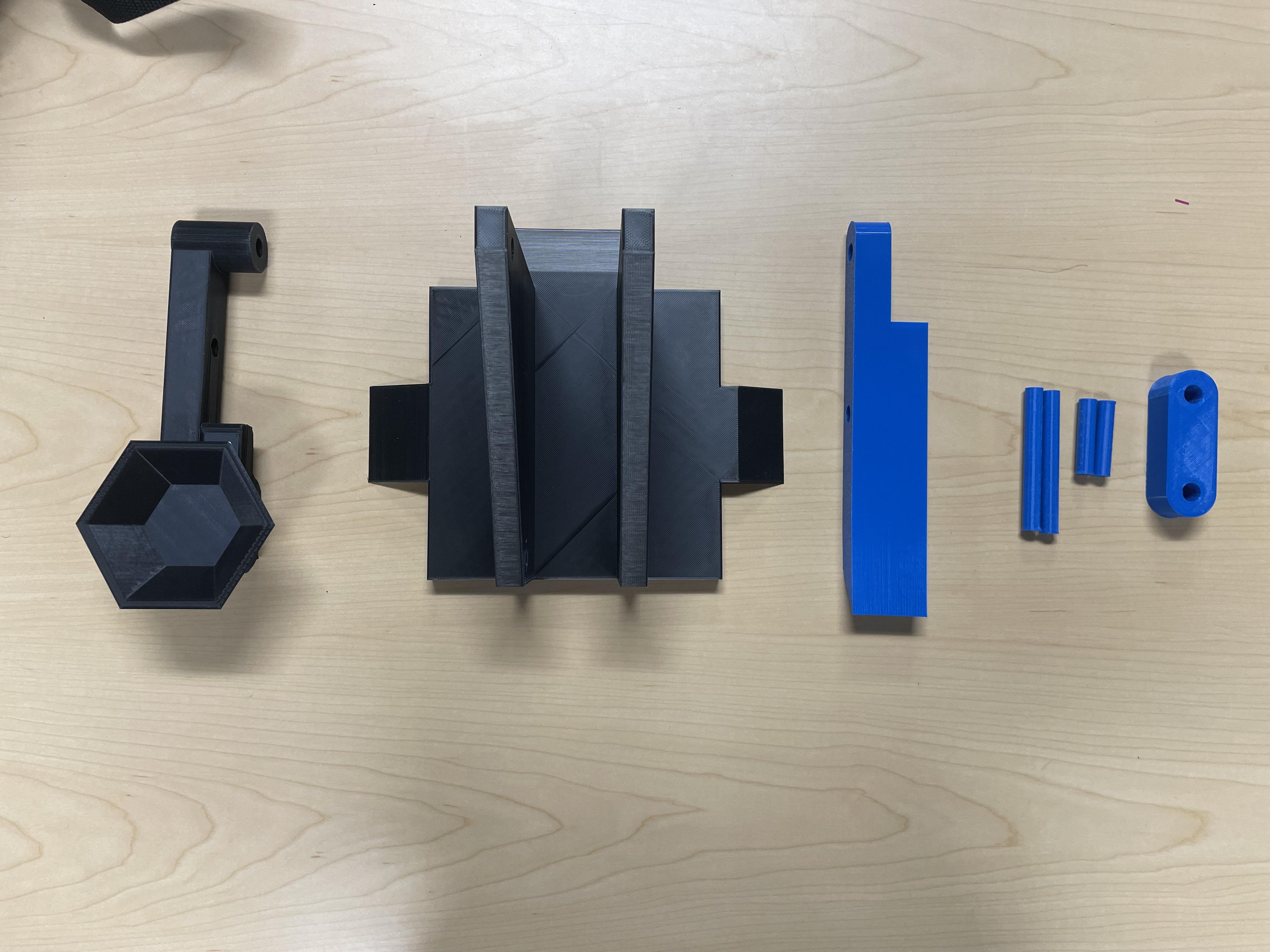
Now all the parts are all designed, we can now assemble it :)
*IMPORTANT
Make sure that when attaching the pins onto the base, "Revolute" is used. Tip: It's also helpful to "Fix" the base into place.
Part 1 - Insert all the parts into an assembly including the launcher assembly made in step 4 (note: Except the launcher and hexagon parts individually).
Part 2 - First use the "Revolute" function and attach one of the main pins to the lever. Be sure to click the middle of the pin when it's facing sideways and the center of the inner circle of the lever. Next use the revolute function to now attach the two onto the base by clicking on the side face of the pin and then clicking on the outer circle of the lowest hole on the base. Note that the side on the lever with the outermost hole is put inside the base and that the longest side of the lever is faced upward.
Part 3 - Next, take one of the inside pins and insert half of it (Half 1) into the lever's outermost hole by using the revolute function. After this revolute lever 2 onto the other half of the inside pin (Half 2).
Part 4 - The "Revolute" function tends to automatically create another revolute, so just "x" out of the function in order to move the parts around. Use a mouse to drag lever 2 upwards (just so there's room to attach the parts together) and click on "Revolute" again to insert half of the second inside pin (Half 3) to the other hole of lever 2. Next, attach the innermost circle of the launcher to the other half of half 3 using revolute.
Part 5 - Take one of the main pins and use the "Revolute" function to attach the second main pin to the other end of the launcher. Be sure to click the middle of the pin when it's facing sideways and the center of the outer circle of the launcher. Next use the revolute function to now attach the two onto the base by clicking on the side face of the pin and then clicking on the outer circle of the lowest hole on the base.
Slicing and Printing
.jpg)
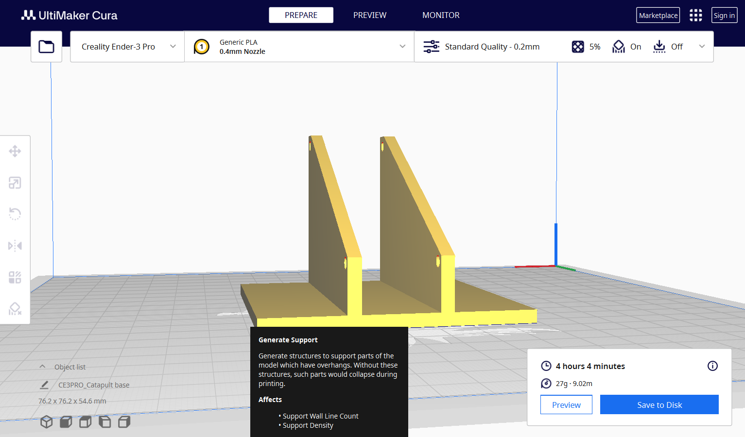
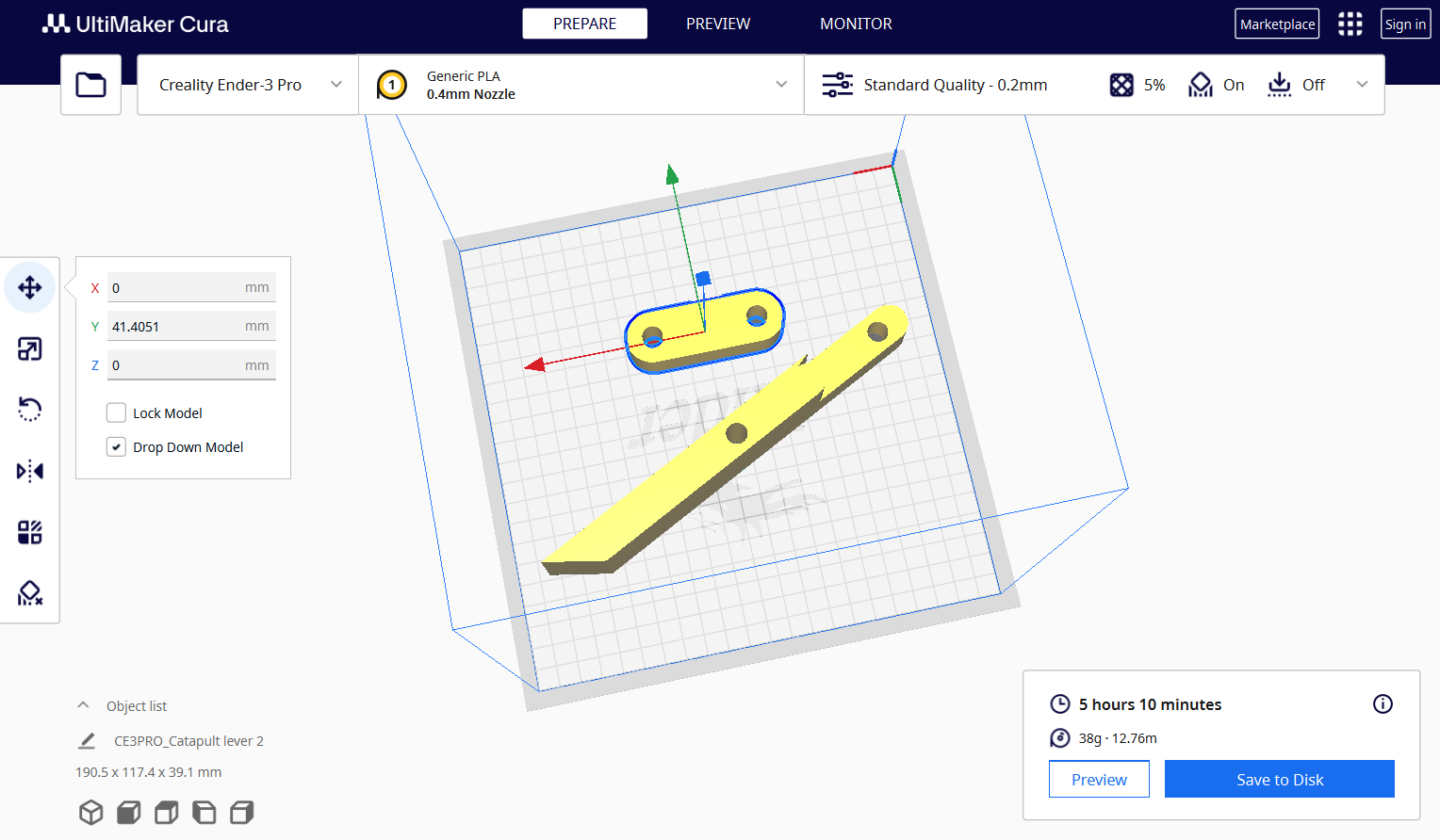
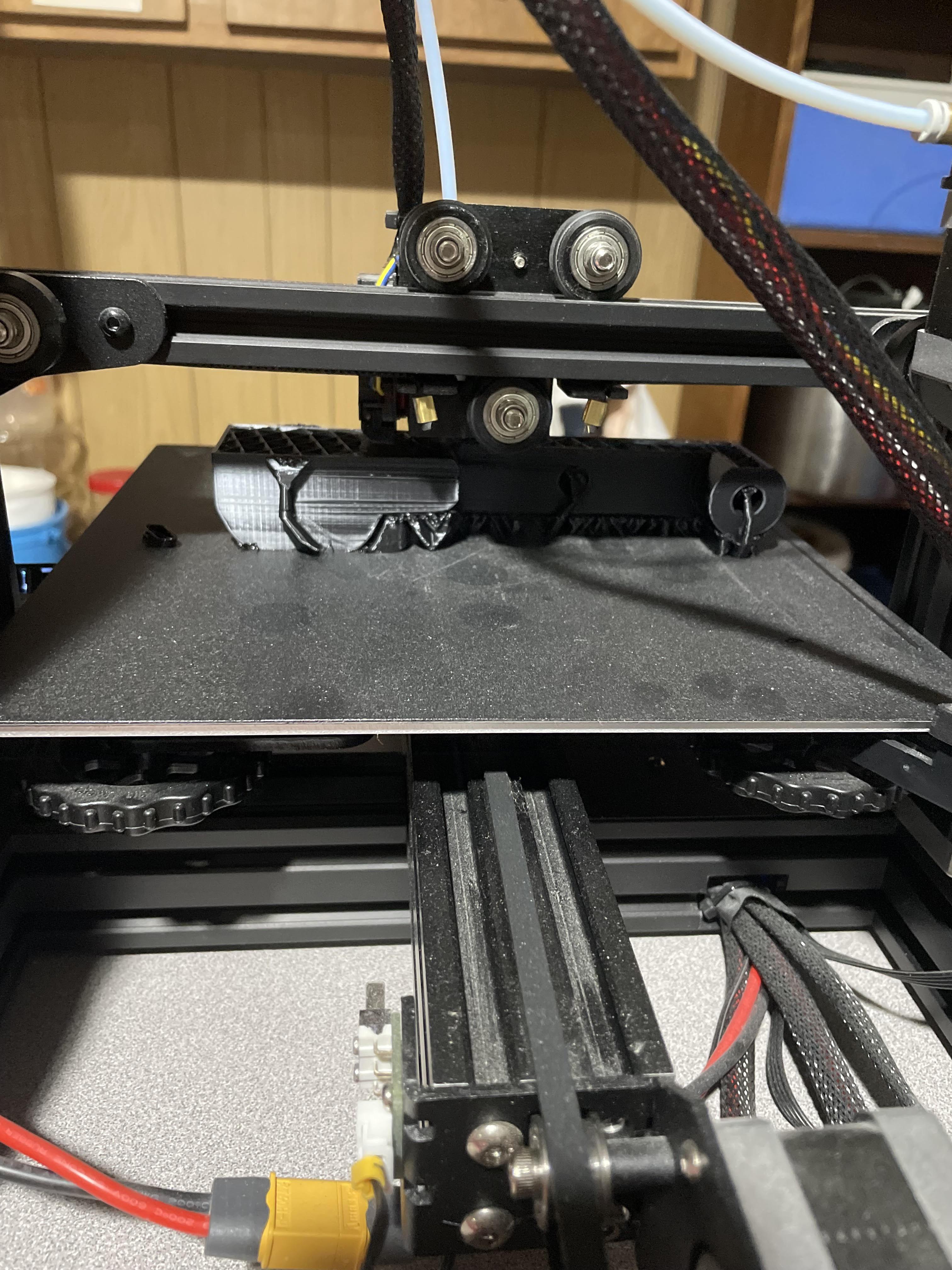
After all the part files were completed, I exported the files and proceeded to open and lay them out on Cura.
Note: The parts might appear humongous when you put the on the plate, however, they will fit onto the plate if positioned in the right way.
So for this catapult, I printed the parts in groups where they could fit on the printing plate and also separated them based on which part needed supports and which didn't.
Printing: Print settings can vary based on many factors whether it be a person's preference, whether the slicing software provides it, or just the model a 3D printer can handle. But in any case, my print settings are as shown below:
Layer Height: 0.2 mm
Initial Layer Height: 0.2mm
Line Width: 0.4mm
Initial Layer Line Width: 100%
Wall thickness: 0.8mm
Wall Line Count: 2
Horizontal Expansion: 0.0mm
Top/Bottom Thickness: 0.8mm
Top Thickness: 0.8mm
Top Layers: 4
Bottom Thickness: 0.8 mm
Bottom Layers: 4
Top Bottom Pattern: Lines
Bottom Pattern Initial Layer: Lines
Infill Density: 5.0%
Infill Pattern: Cubic
Printing Temperature: 220.0 ºC
Build Plate Temperature: 60.0 ºC
Print Speed: 50.0 mm/s
Travel Speed: 150.0 mm/s
Initial Layer Speed: 20.0 mm/s
Initial Layer Print Speed: 20.0mm/s
Initial Layer Travel Speed: 100.0 mm/s
Z Hop Speed: 5.0 mm/s
Number of Slower Layers: 2
Enable Print Cooling: Checked
Fan Speed: 100.0%
Support (For Launcher only): Checked. Support Structure: Tree. Support Placement: Everywhere. Support Overhang Angle 45.0%.
Total parts needed: 8
1 Base
1 launcher (Needs support)
1 Lever
1 Lever 2
2 Inside pins (Print pins standing up)
2 Main pins (Print pins standing up)
I printed the levers together, the pins together, the base separate, and the launcher separate (launcher needs support). After slicing the parts, save into a removable drive and transfer into a micro SD card (3D printing chip) and make sure to level the printer before using it.
When all the parts are printed, all that's left is to assemble it and launch things to your heart's content. :)
Additional Tips+ Conclusion
.jpg)
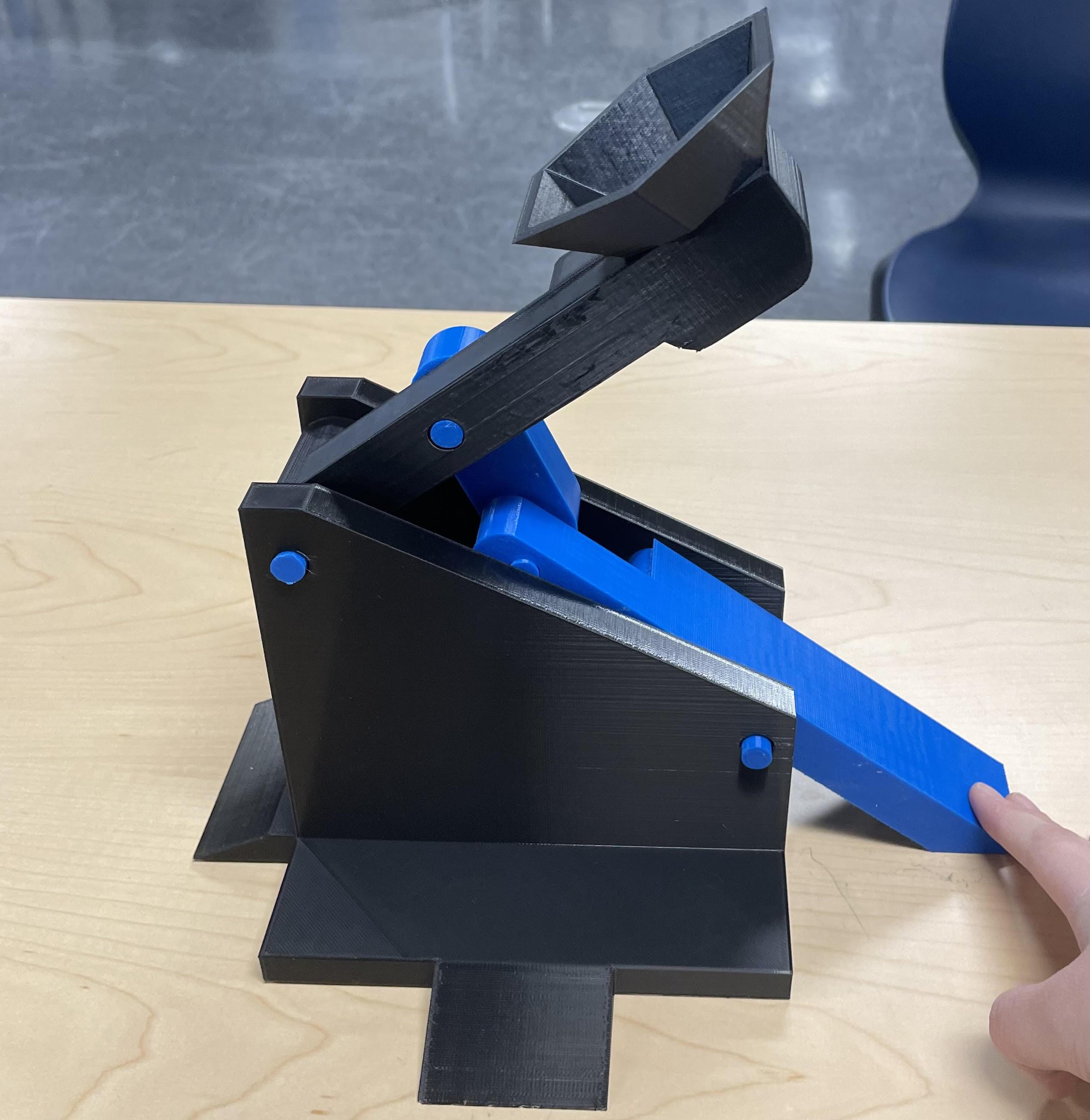
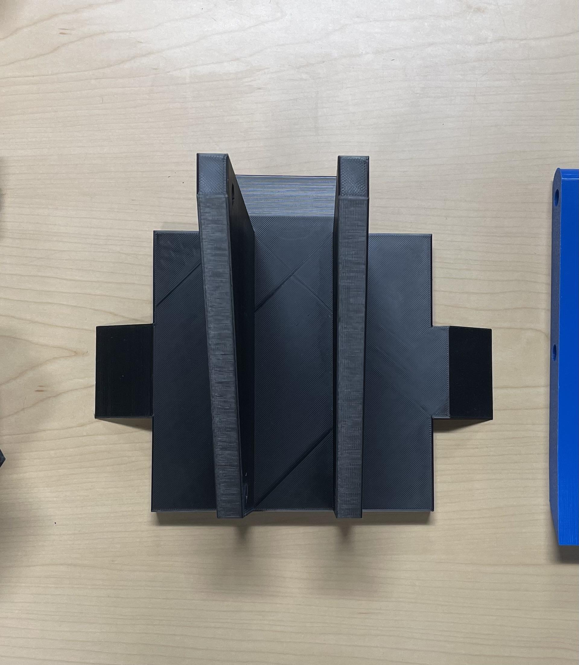
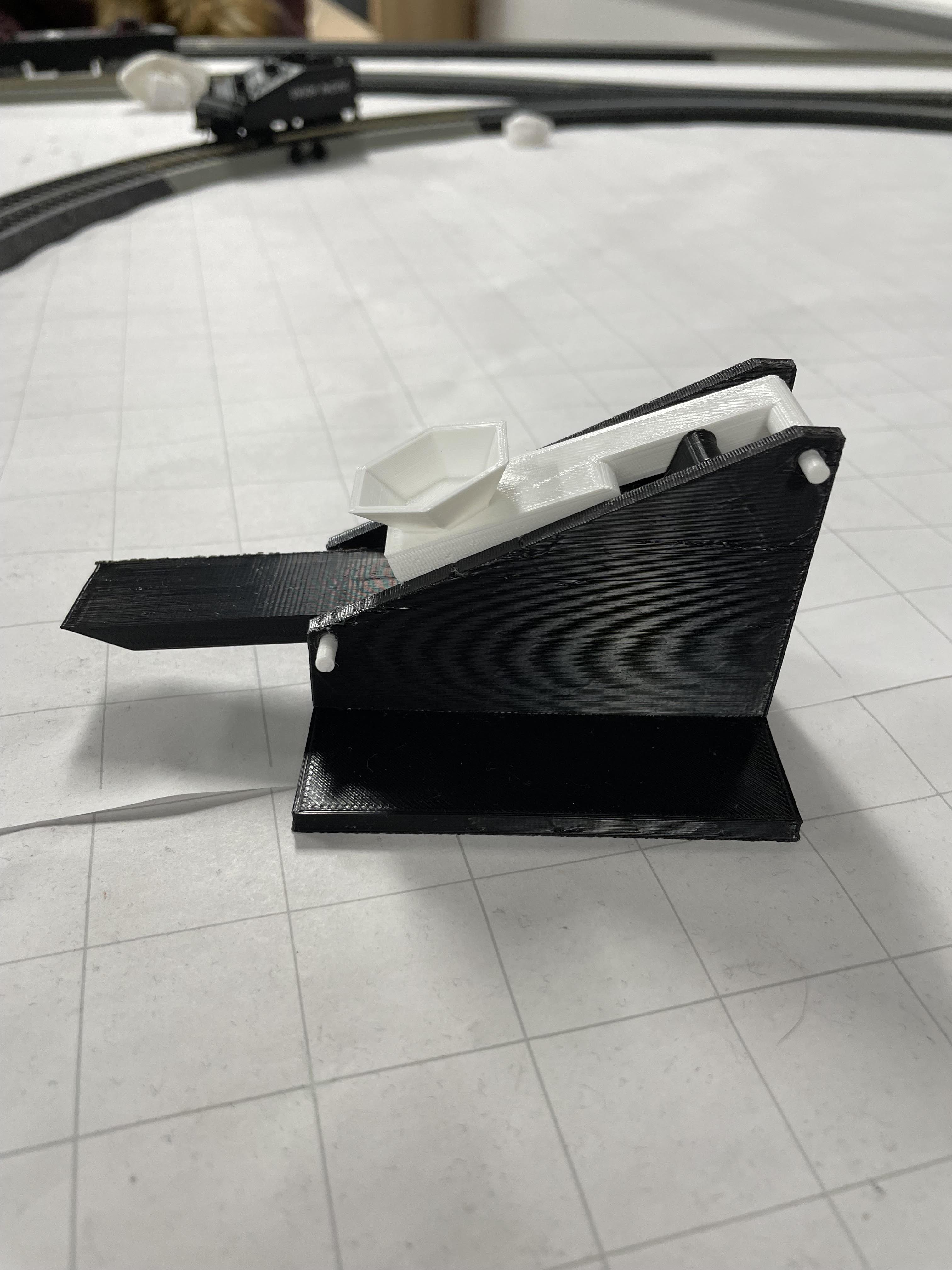
- Tip 1: Design structure: For the structure of the catapult, I made the base and launcher a little more heavier than the other parts. With the initial prototype I realized that the base would slightly jump each time I launched something. Therefore I added "wings" to each side in order to increase the catapult's surface area and prevent it from jumping and potentially not launching the projectile as far as it should.
- Tip 2: Unneeded Brim: Although many might have different opinions than me on this, I personally prefer to not use the brim function. The brim function usually aids in holding the print down on the plate so it doesn't fold upwards on the corner or sides of the bed if the bed isn't heated enough. Additionally, it slightly reduces printing time and saves a few inches of the filament roll.
Conclusion: Overall this project took me about 2 weeks (During 3D Design class and weekends) to create, including all the modifications made from the original prototype. Throughout this project, I ended up learning the physics and mechanisms of a successful launcher which really helped in creating an effective catapult.
Launch! :)
