Forklift Clock
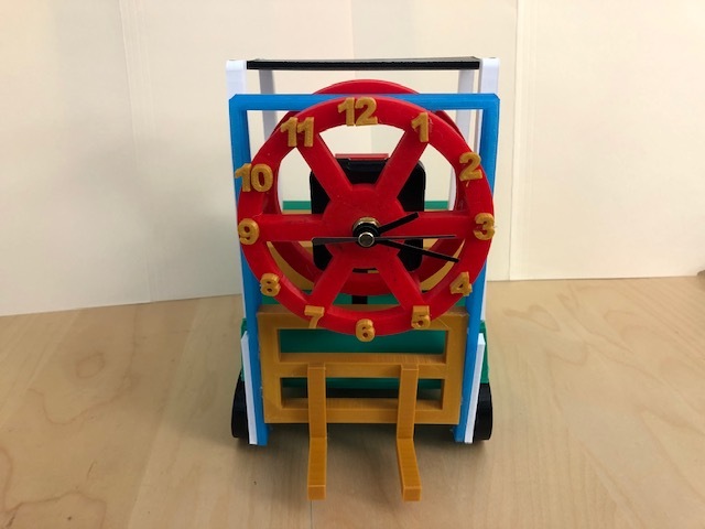
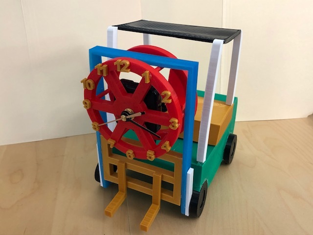
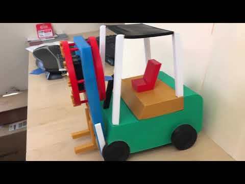
Designing clock is a first experience for me. Most old clocks are noisy, so I decided to challenge myself in this contest to make a silent portable clock with unique design. All you have to do is having a 3D design software and Printer. Yet, the printer itself is optional. There are a lot of services in 3D Printing. Let us make this clock.
You can find my design here in Cults3d.
Preparing 3D Design
Open Fusion 360 Software. If you want to download it, you can click here (it is free for students, teachers, and educators) or here (it is only a free trial for people not related to education).
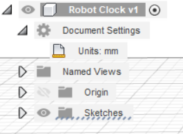
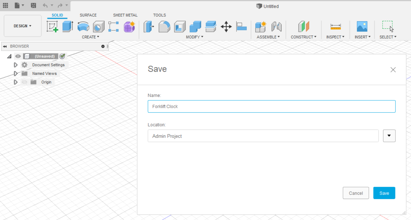
Open the blank document and save it by clicking the "Save" button. Do not forget to choose the location of the file. Here, my project has a name of Robot Clock, and I saved it in the Admin Project folder. Before you are making the project, change the units of measurement as you desired by clicking the document settings in the top left side of the window (see picture). The default is in mm. I choose mm for the units of measurement in this project because it is more precise and accurate.
Sketch for Front Part of Clock Wheel
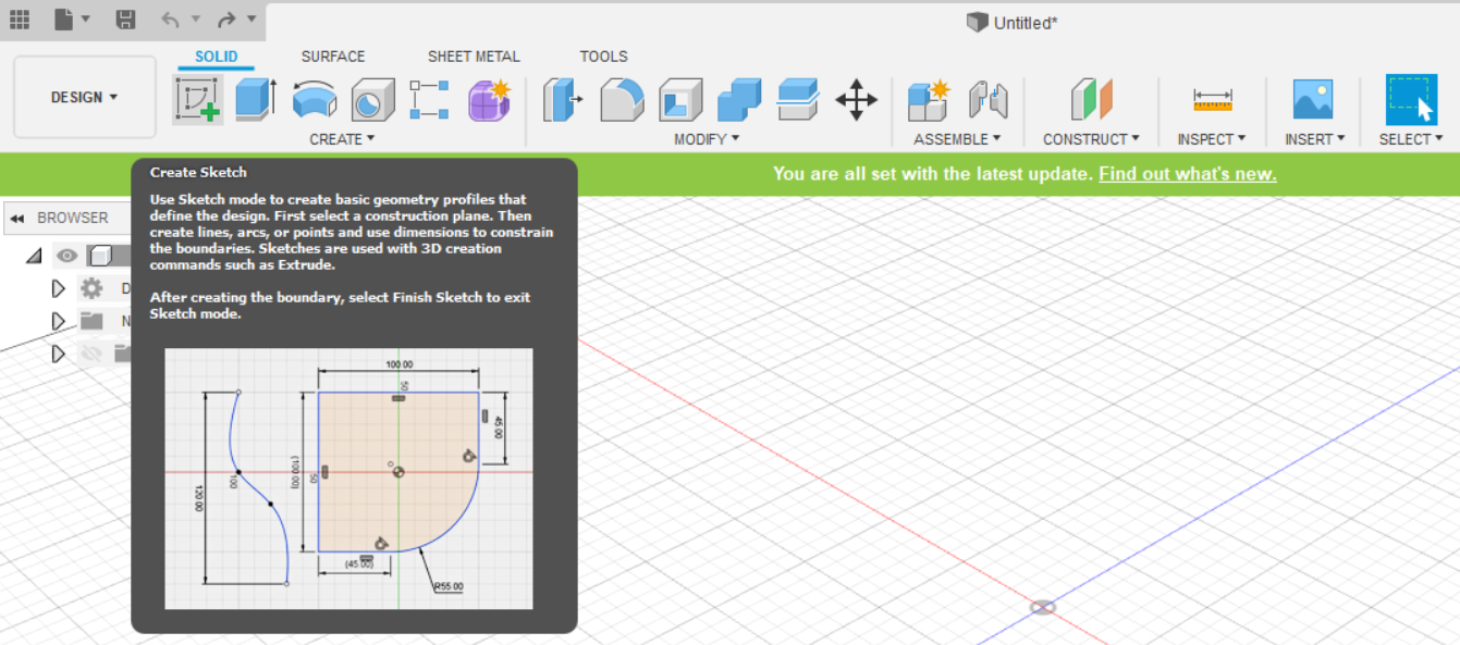
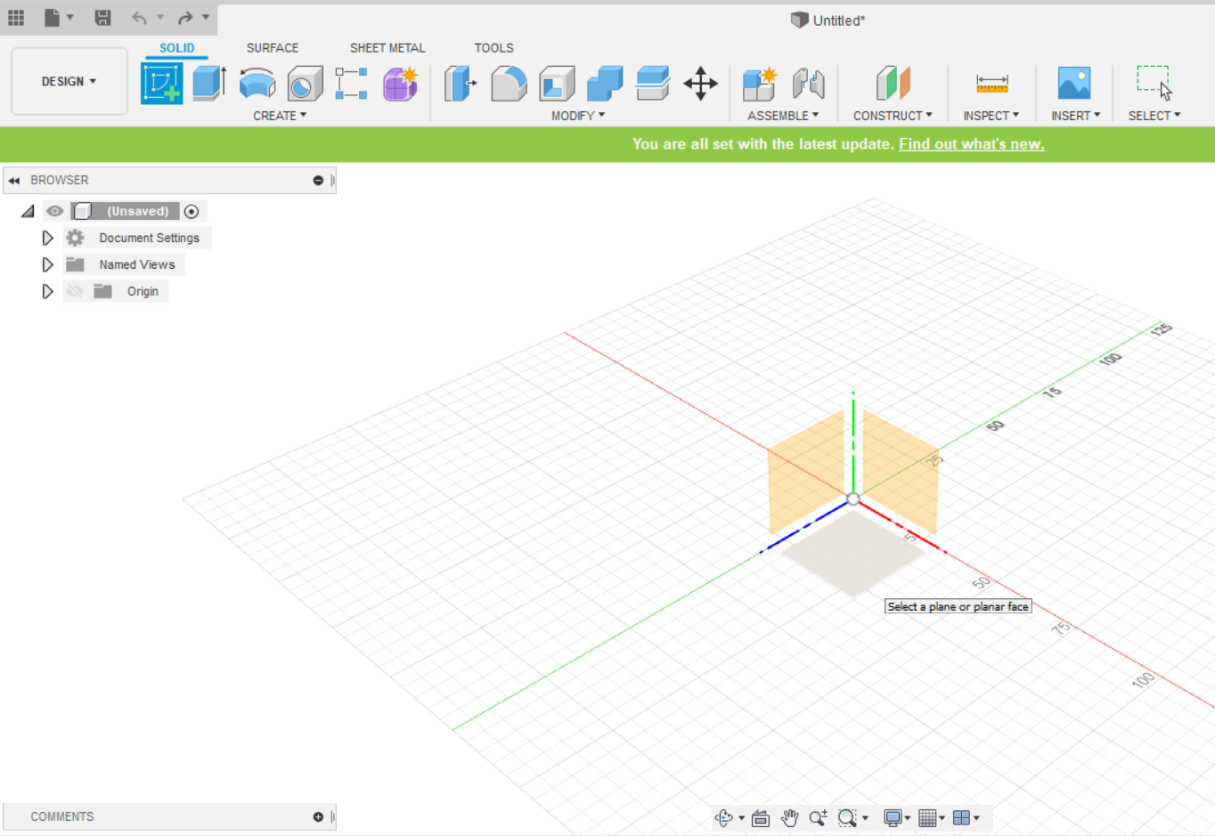
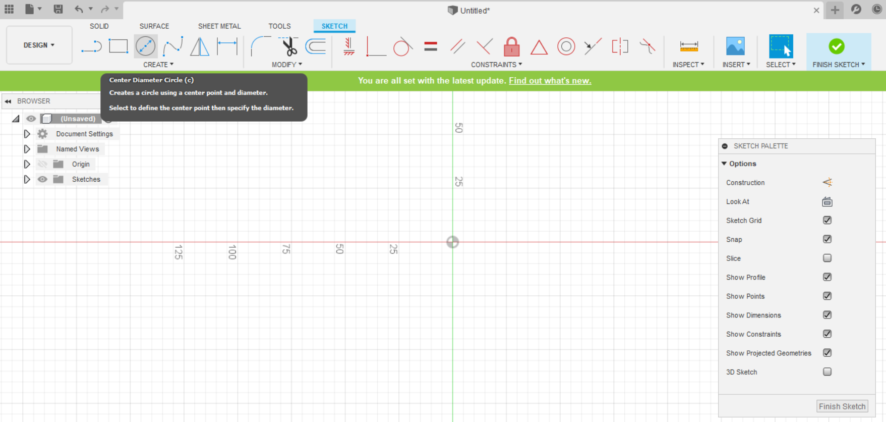
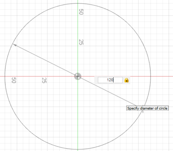
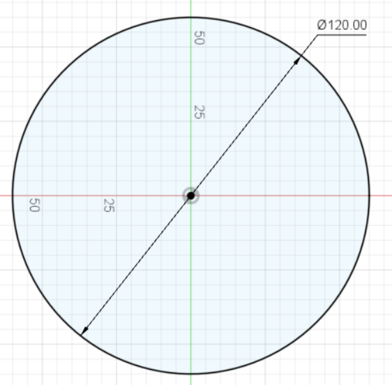
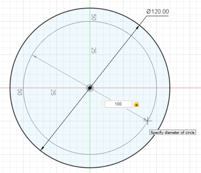
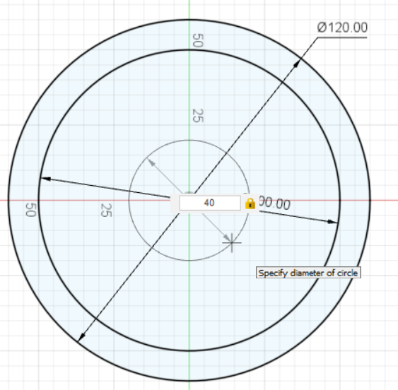
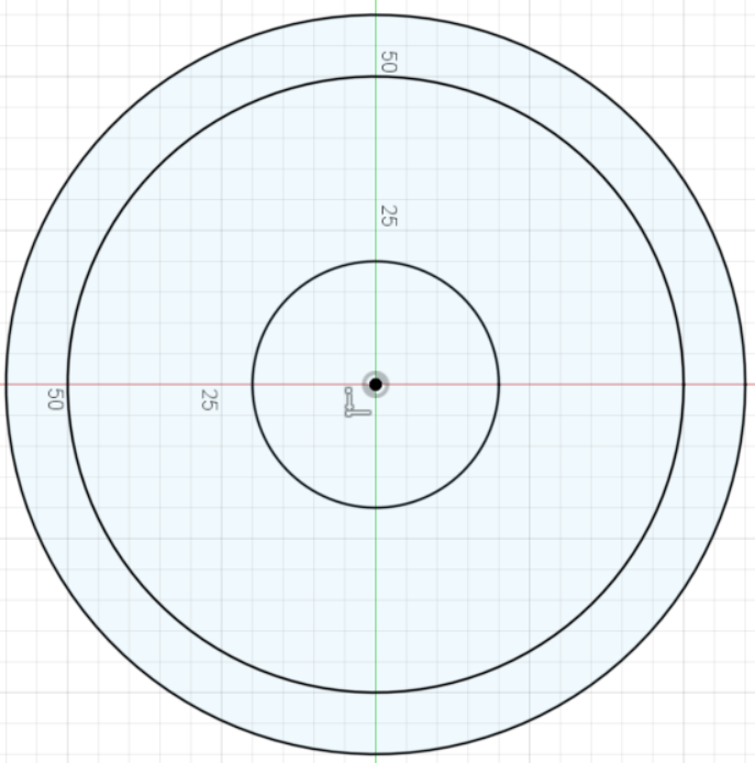
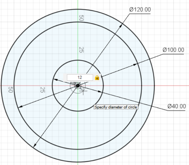
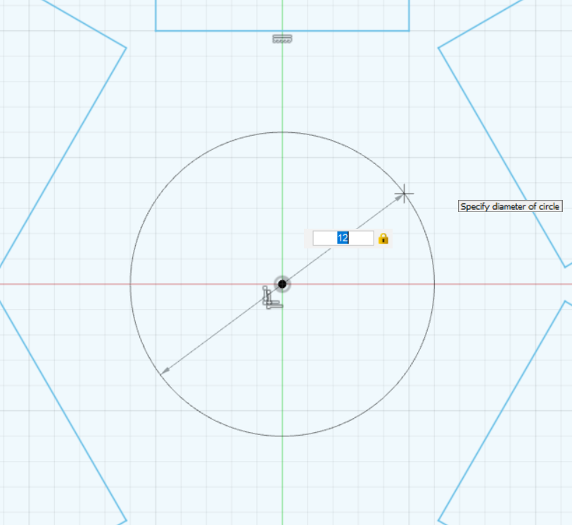
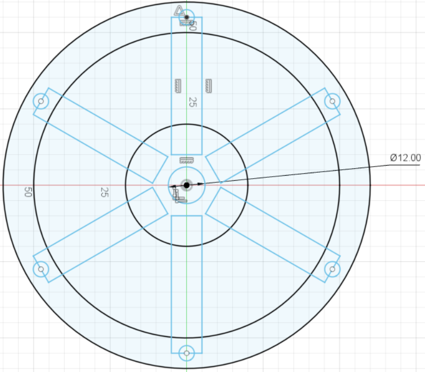
Start creating a sketch. Select the plane, and click the Center Diameter Circle in the Create tab. This project needs 3 circles for making a wheel. Input the diameter of the first circle to 120 mm, the second circle 100 mm, and the third circle 40 mm.
Sketch Spokes of Front Part of Clock Wheel – Pt. 1
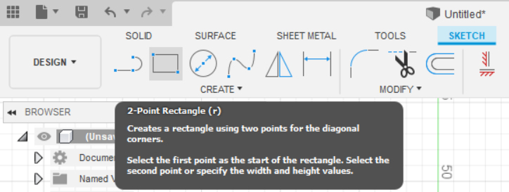
To create spokes, you need a rectangular shape by clicking the "2-Point Rectangle" button in the Create tab.
Sketch Spokes of Front Part of Clock Wheel – Pt. 2
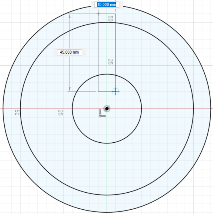
Sketch Spokes of Front Part of Clock Wheel – Pt. 3
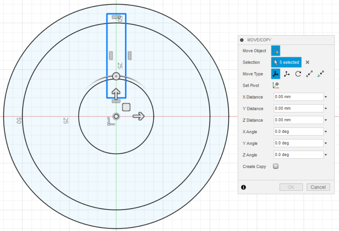
Sketch Locking Pins – Pt. 1
Sketch Locking Pins – Pt. 2
Sketch for Center Circle of Clock Wheel
Sketch for Back Part of Clock Wheel – Pt. 1
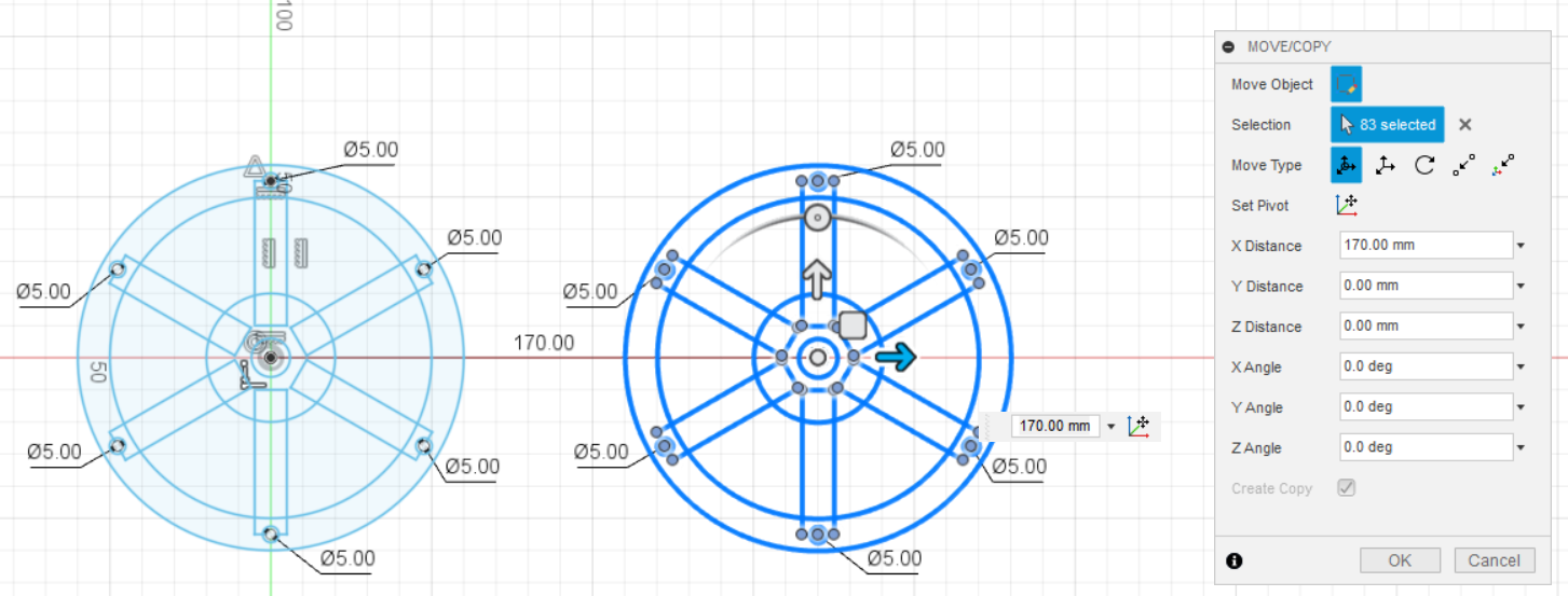
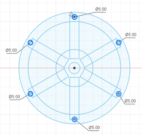
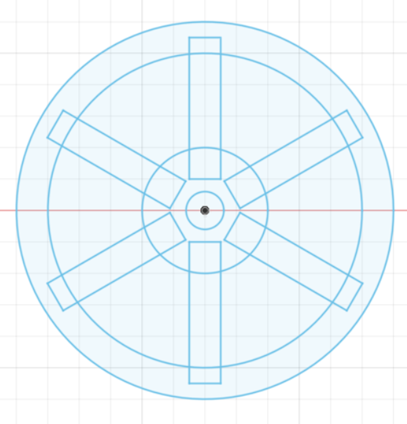
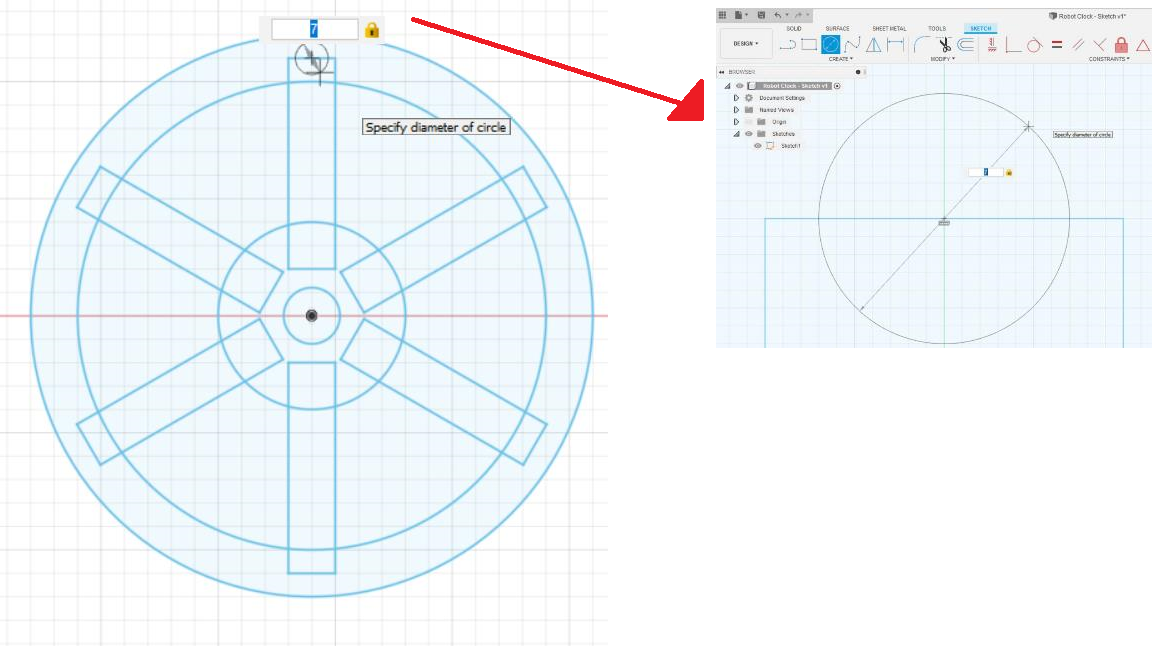
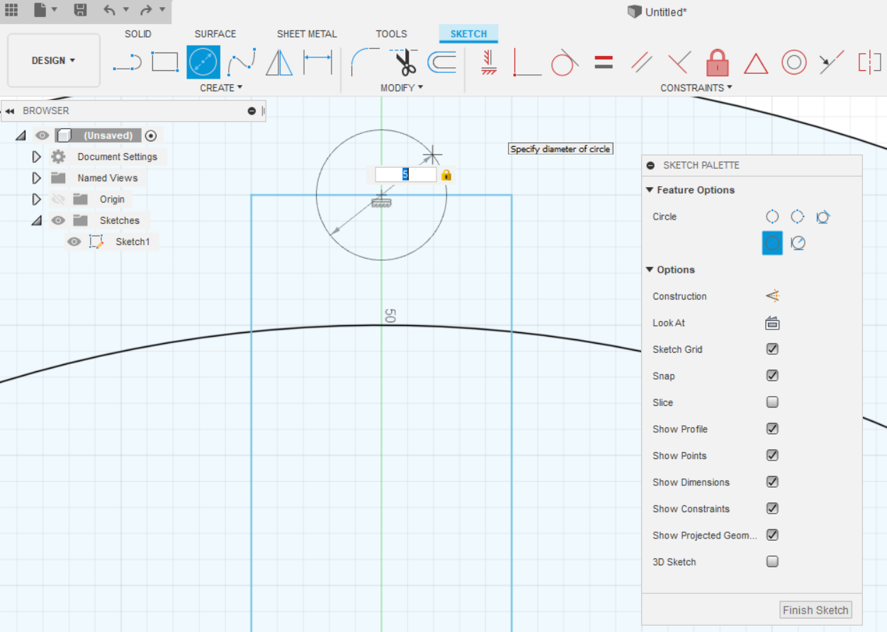
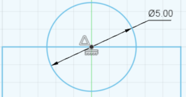
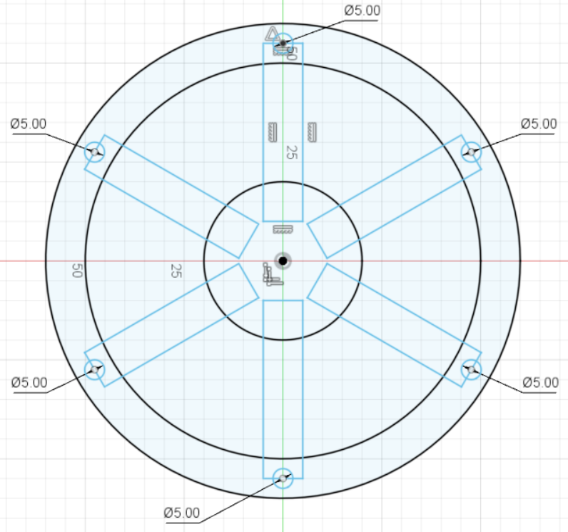
Select all the wheels and click the Copy button. Drag the copy to another place in the Workplane. Select all the Locking Pins. Delete them all. Create another hole for the locking pins attachment with a diameter of 7 mm. You need 7 mm for the hole of the locking pins attachment because the diameter of the locking pins is 5 mm. Therefore, you must have the diameter of the attachment holes for 7 mm, which is 2 mm more than the diameter of the locking pins. The benefit for doing this is that the locking pins will be able to attach and enter the hole properly.
Sketch for Back Part of Clock Wheel – Pt. 2
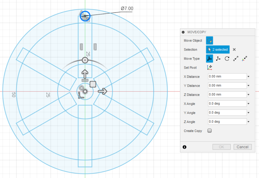
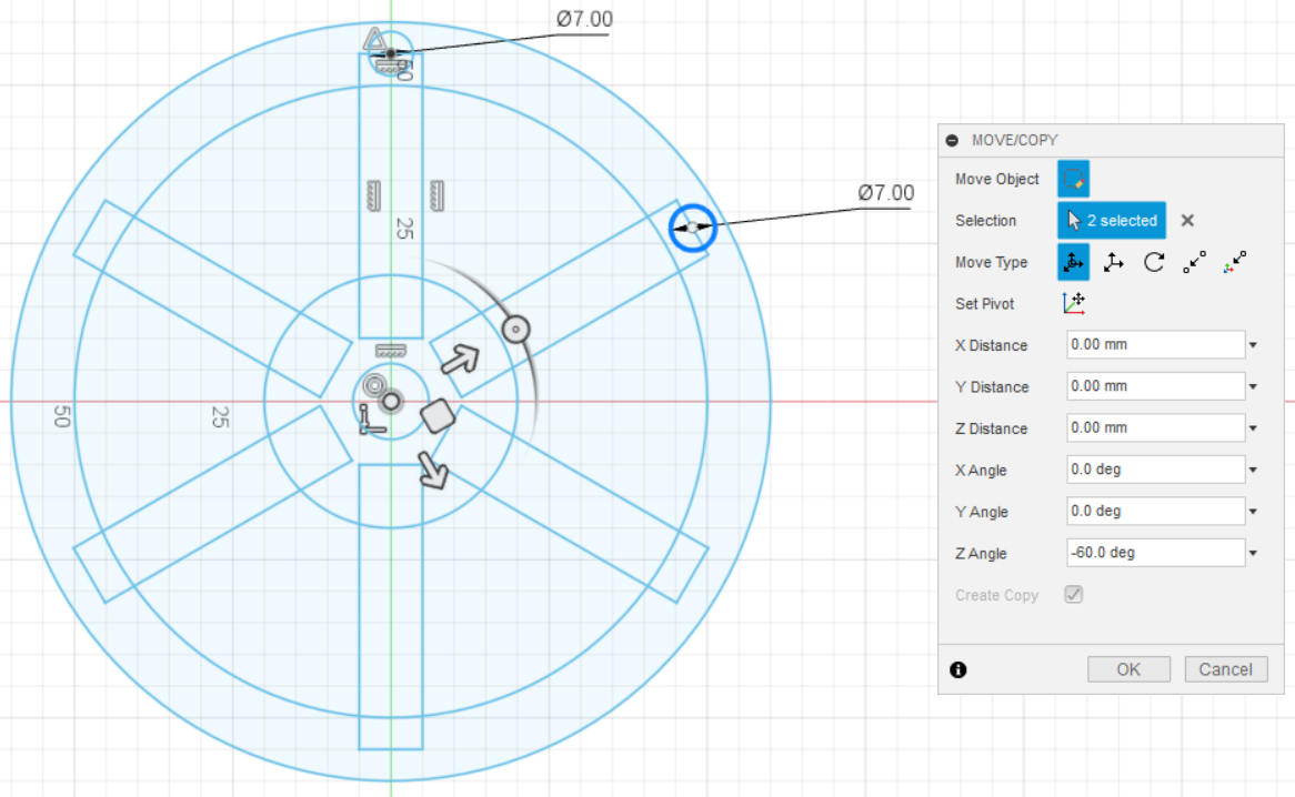
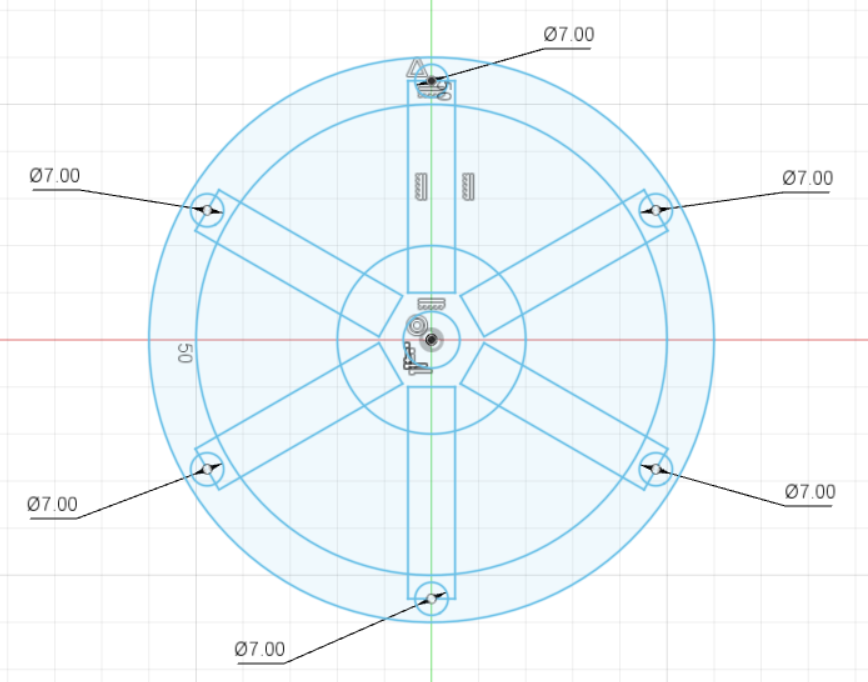
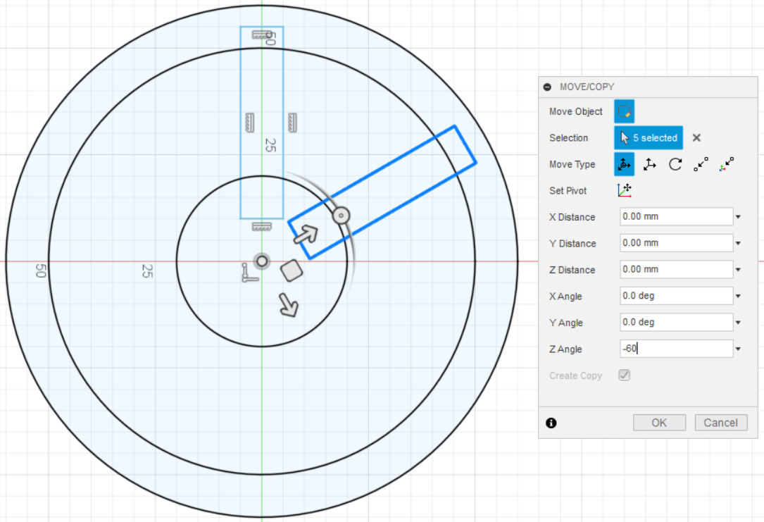
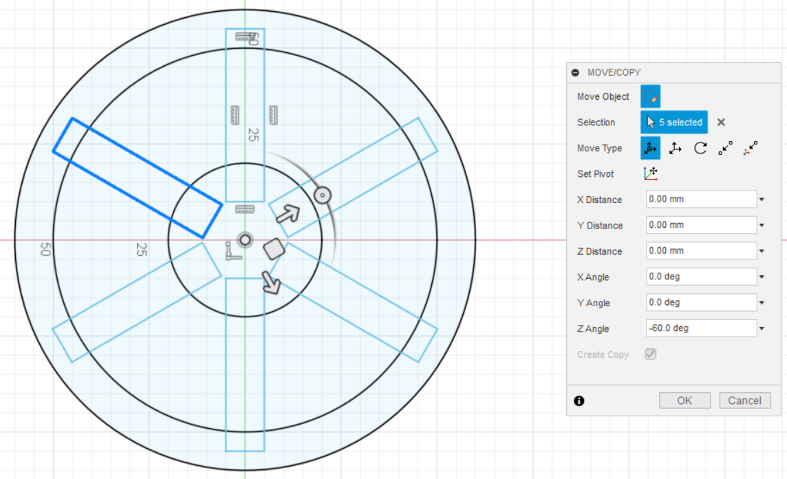
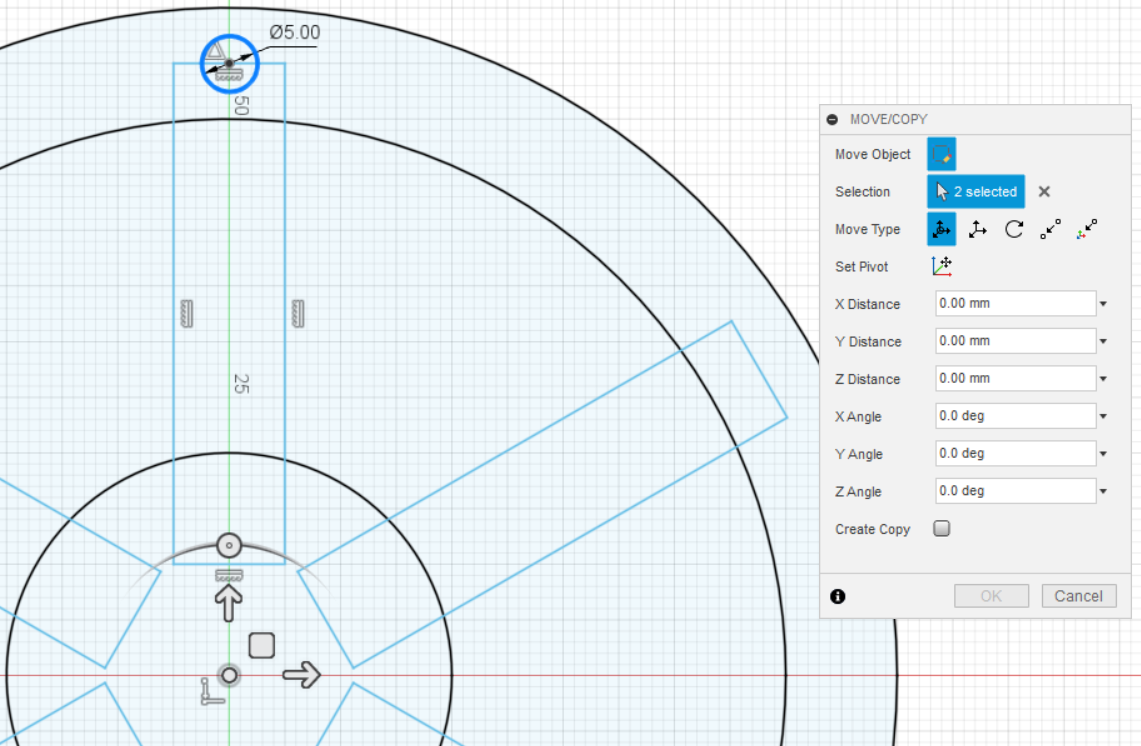
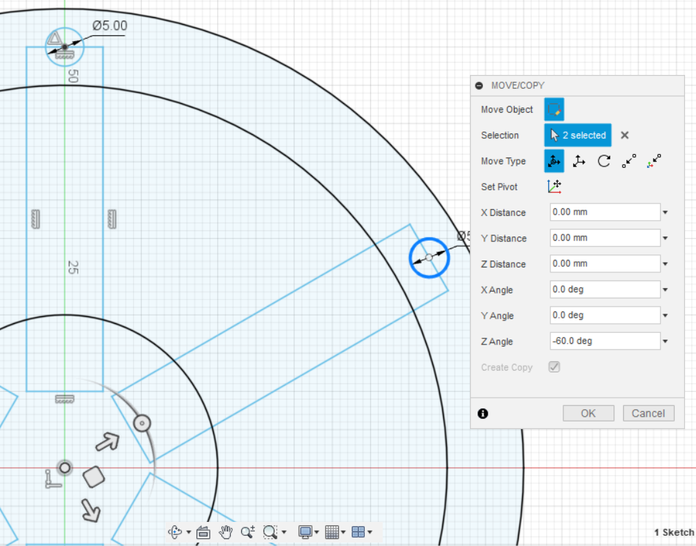
Copy the hole for the locking pins attachment by selecting the center of the Wheel. After that, select the Circle by using Shift key. Type "-60" into the "Z Angle". Do that for 5 times.
Sketch Forklift Wheel
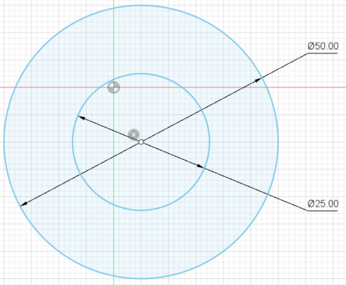
To make the wheel of the forklift, draw it in the sketch view. It is far easier than constructing it in 3D view. First, draw the circle by clicking "Center Diameter Circle" the Sketch Mode. Make 2 circles with a diameter of 25 mm and 50 mm. Duplicate the wheel.
Sketch Forklift Body
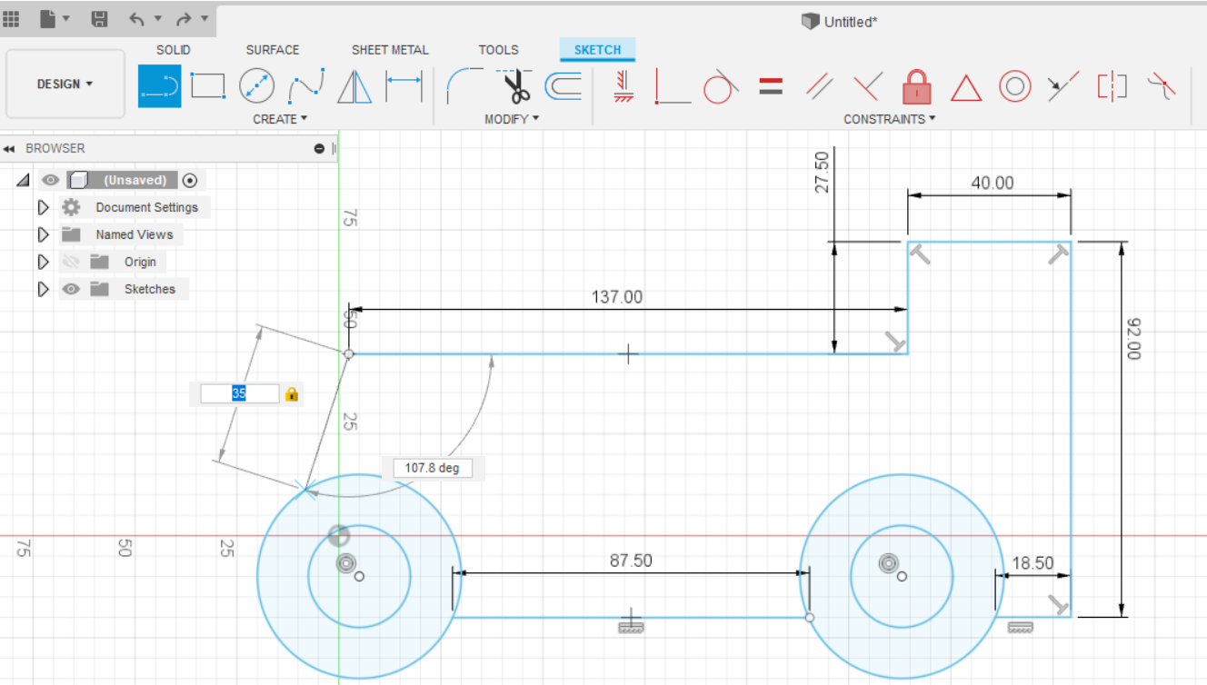
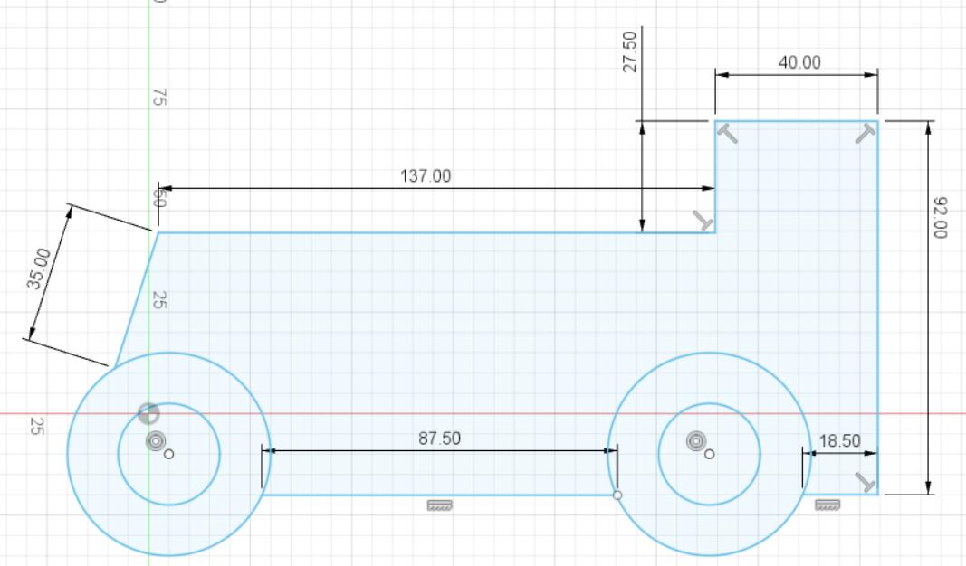
Create the forklift body with the dimensions are shown in the picture. All the unit measurements are in mm.
Sketch Overhead Guard and the Support
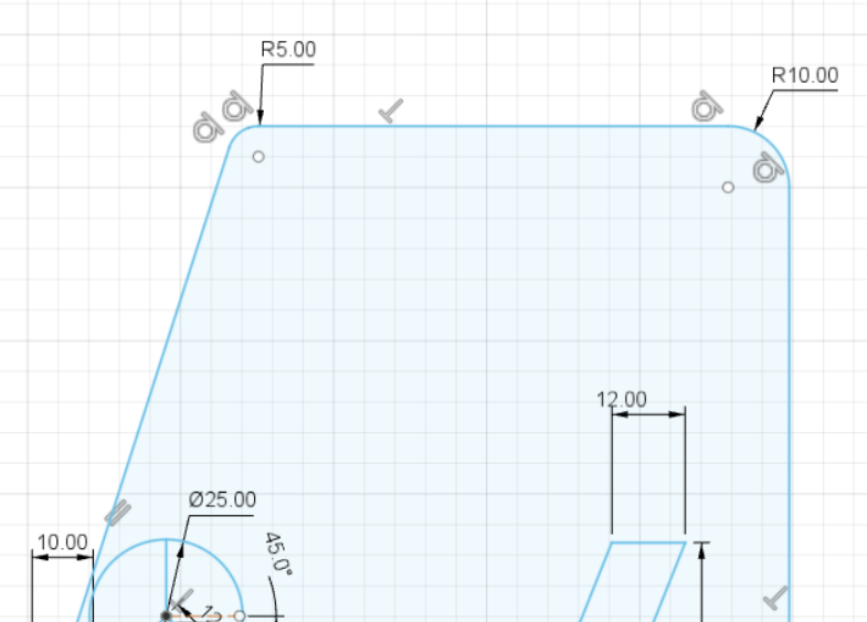
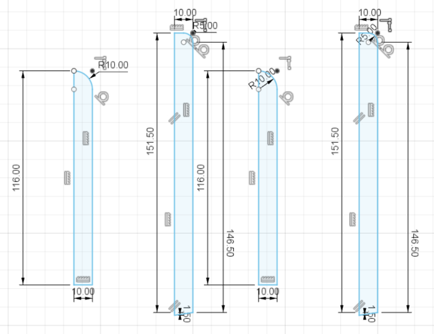
Sketch the overhead guard and the support. The sizes are noted in the image.
Sketch Forklift Mast
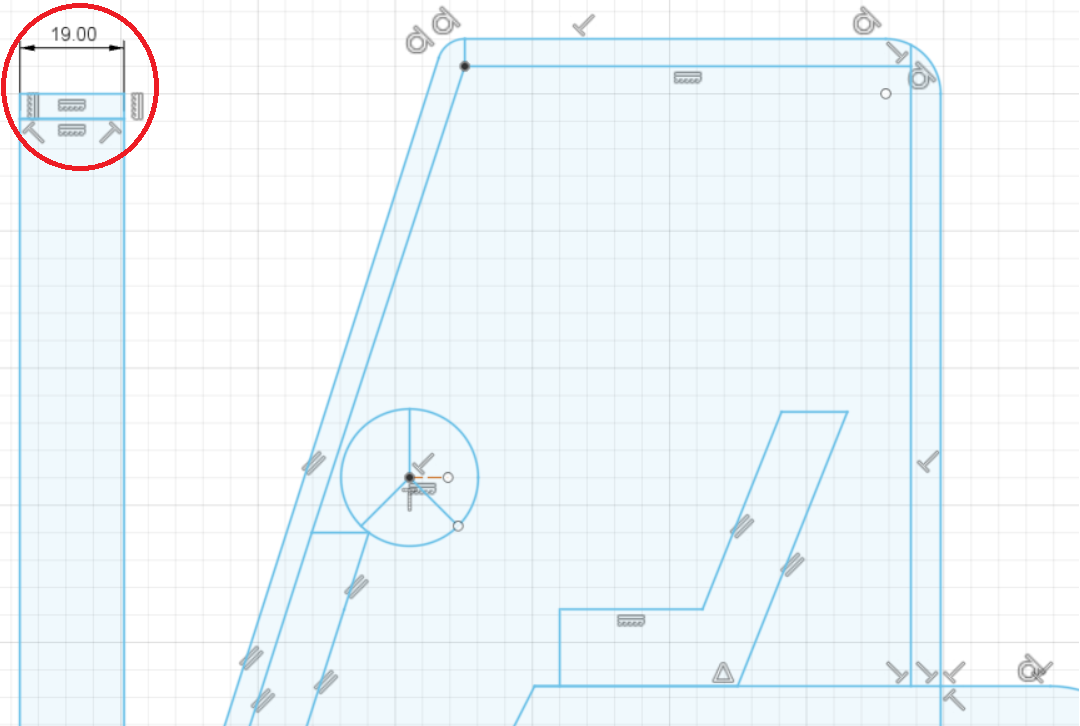
Sketch the forklift mast with a width of 19 mm as shown in the picture.
Sketch Forklift Operator Cab
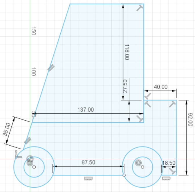
Make another sketch for the operator cab. See the image for further measurement.
Sketch Forklift Load Backrest and Forks
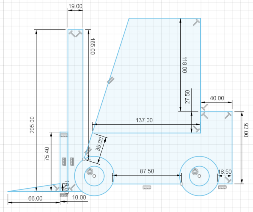
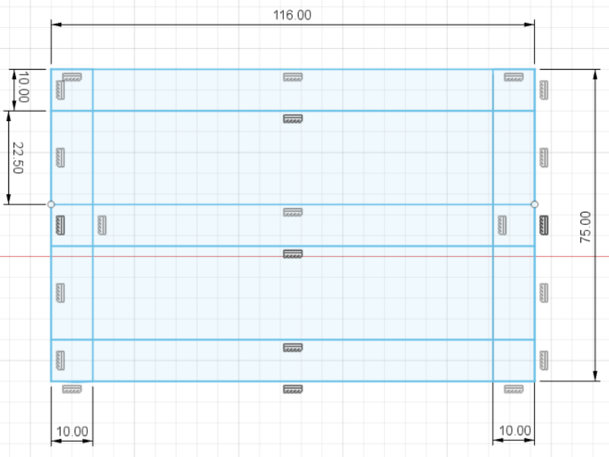
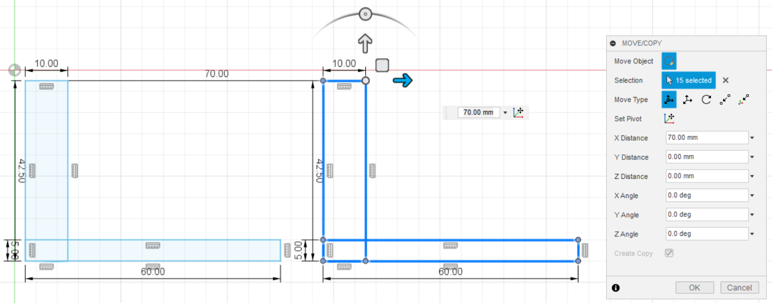
Moreover, draw the sketch for the load backrest and the forks of the forklift. See the picture for the measurement. First, my drawing is triangle-shaped for the load forks, yet turnout, after printing, they are too fragile to be attached in front of the load backrest. Therefore, I decided to change my sketch for the forks. I drew L-shape Forks and the result is that they are sturdy.
Sketch Seat
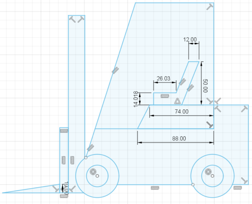
Then, draw the seat. See the picture for the sizes.
Sketch Forklift Steering Wheel
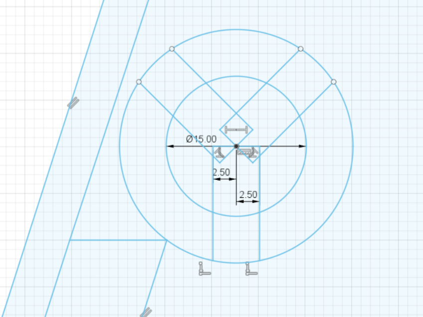
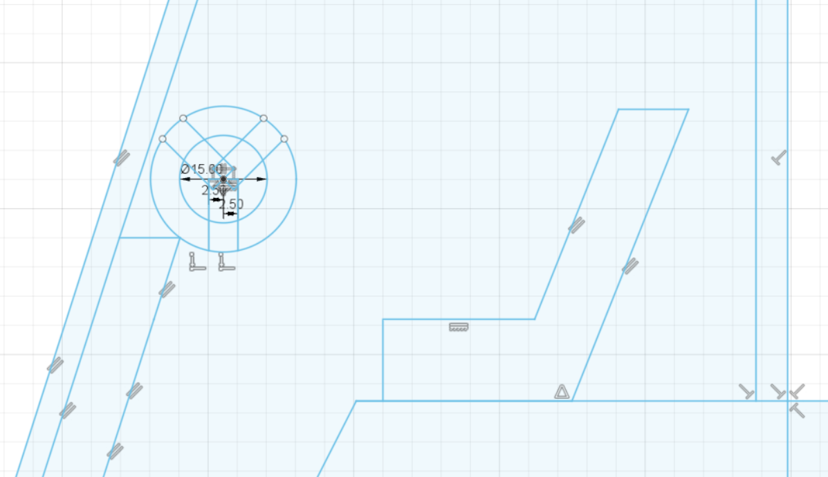
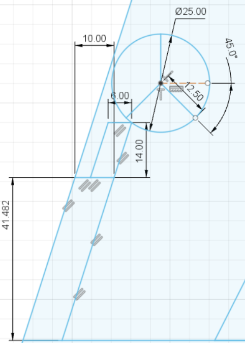
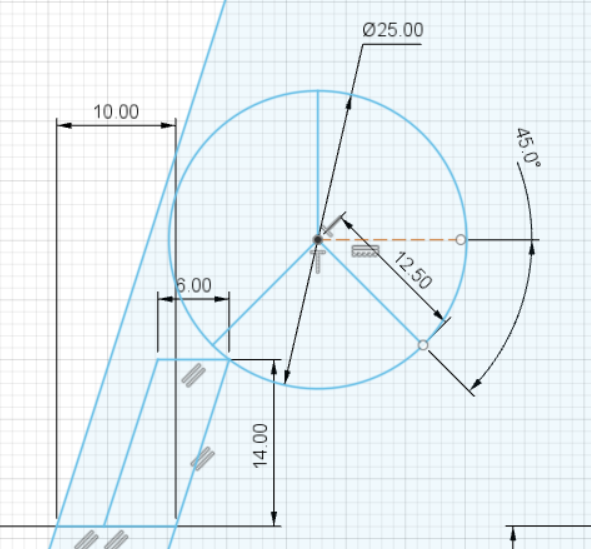
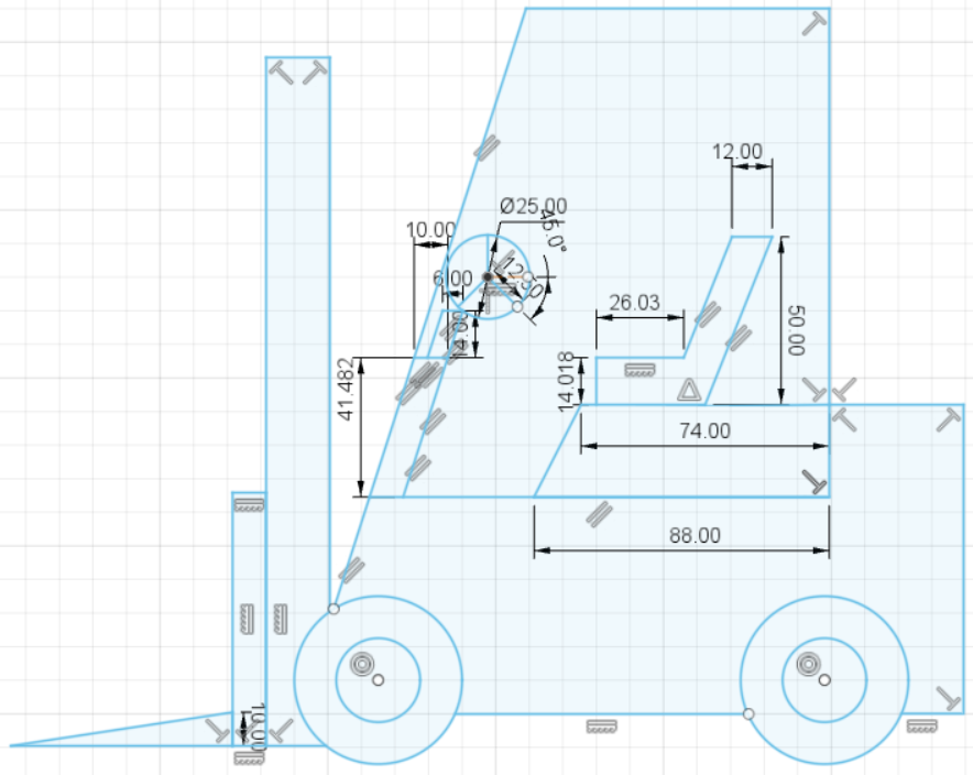
Draw the Steering Wheel also. See the picture.
Extrude Clock Wheel – Pt. 1
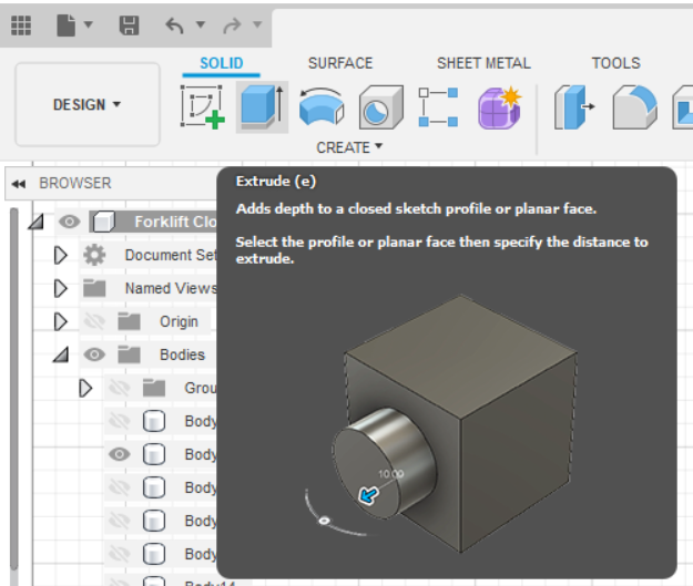
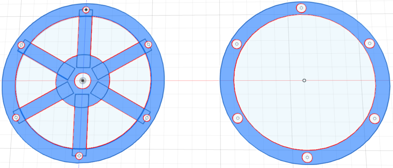
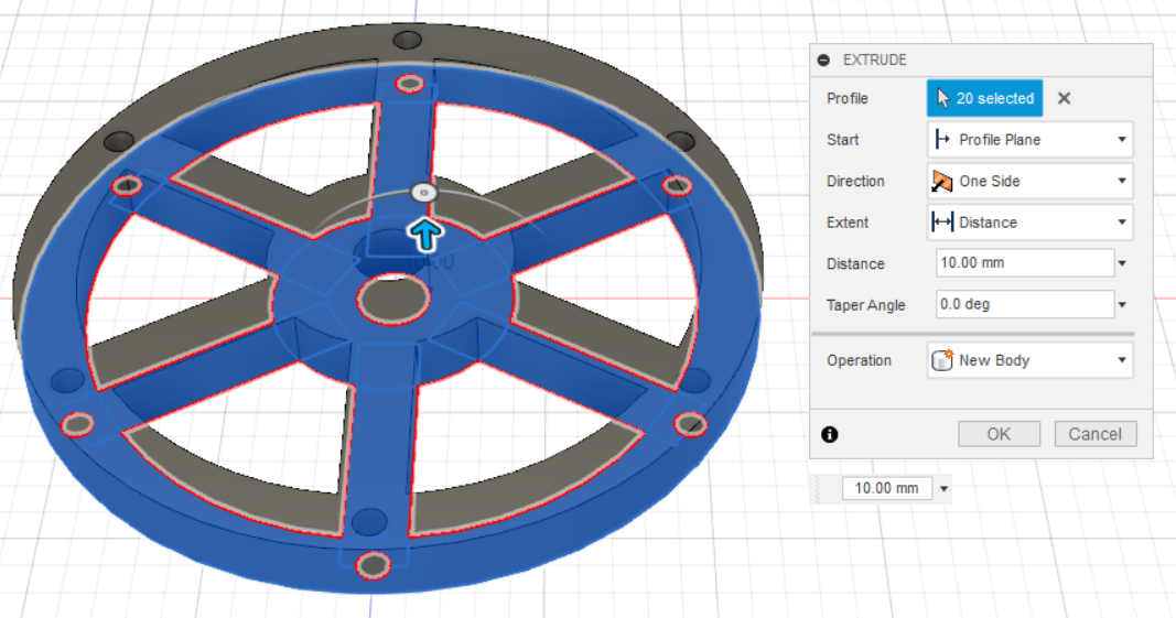
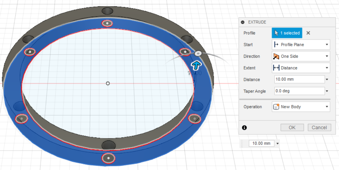
Extrude the Front and Back Parts of the Wheel by clicking Extrude button or press shortcut key E. Select all the faces, except the holes for the locking pins and the clock mechanism. Extrude them for 10 mm of height.
Extrude Clock Wheel – Pt. 2
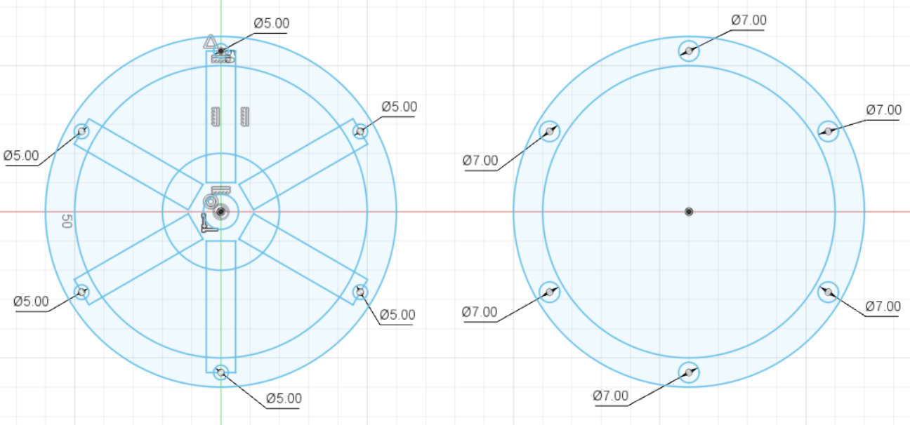
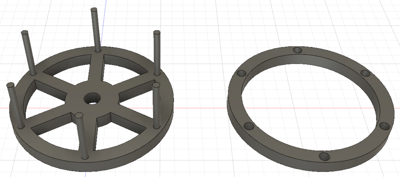
Select all the holes that have a diameter of 5 mm, not 7 mm. Extrude the locking pins in the front part of the wheel a thickness of 10 mm. For the back part of the wheel, extrude all, except the hole for the thickness of 10 mm. By doing this, you will get the holes perforated completely, yet we do not want the back part of the wheel to have holes. We want the hole only in one side of the back part of the wheel, just for sticking the locking pins. Therefore, we need to extrude another 5 mm for the other side of the wheel part.
Preparing for Printing the Clock Wheel
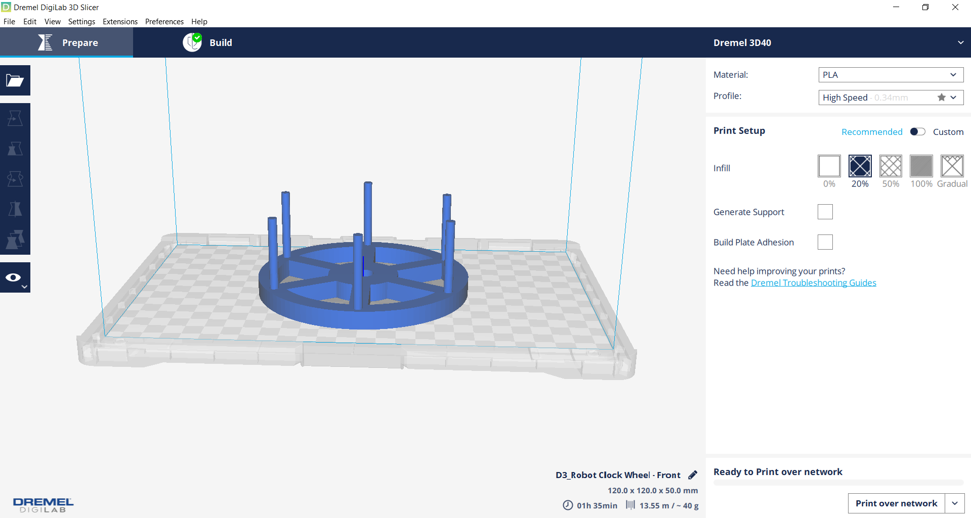
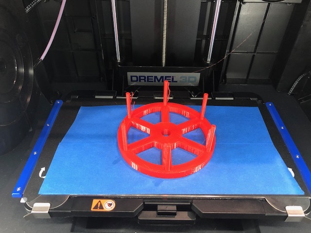
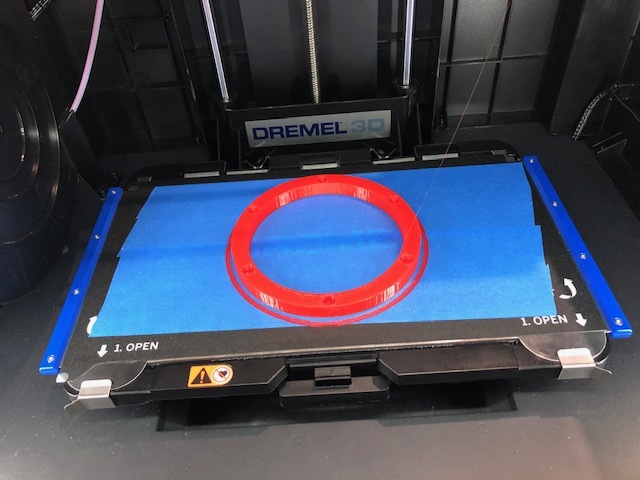
Export the Clock Wheel into an STL File in order for it to be printed. I used the Dremel Digilab 3D40 as the 3D Printer. For more information and options, click here. Open the STL file in the Dremel Digilab 3D Slicer (or you can just drag the File into the slicer). Adjust the position as you prefer. The Clock Wheel is automatically in the Slicer. I used "High Speed" and "20% of infill". Then, click Prepare button for Slicing. Lastly, click print.
Extrude Forklift Wheels – Pt. 1
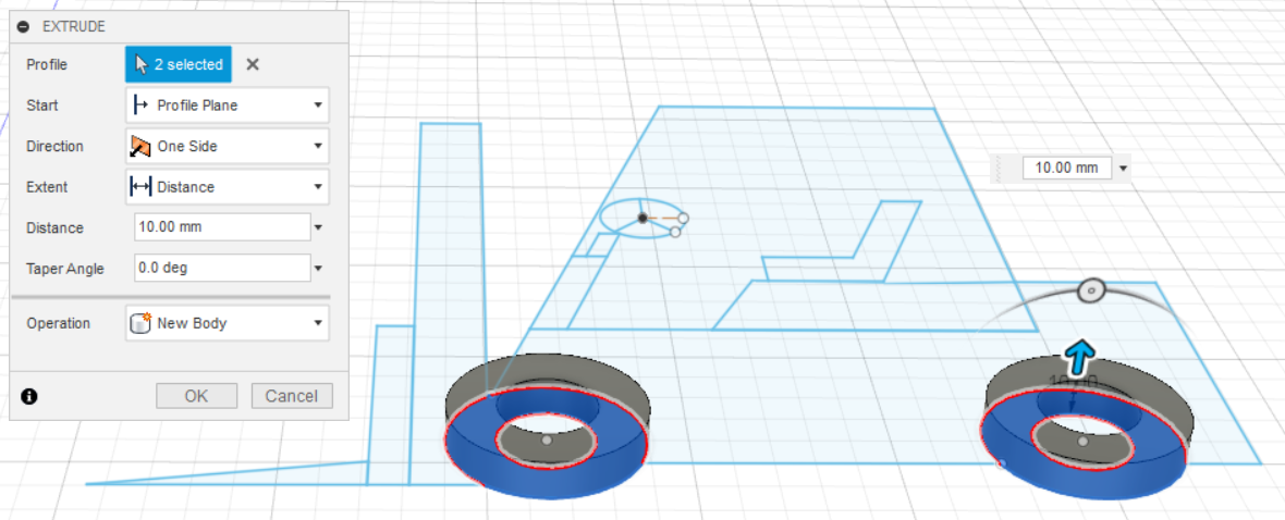

After finishing sketching the forklift, extrude the parts one by one. Start by extruding the wheels. Select the wheels faces. Click the E button on your keyboard to extrude. Extrude for the dimension of 10 mm. Yet, in this case, we extrude the tires (the front part of the wheel).
Extrude Forklift Wheels – Pt. 2

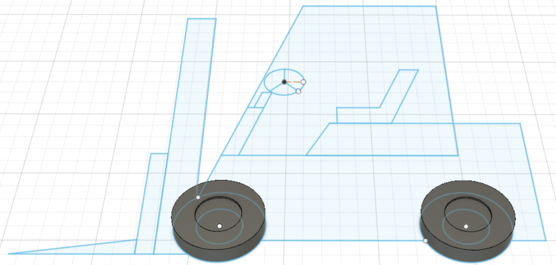
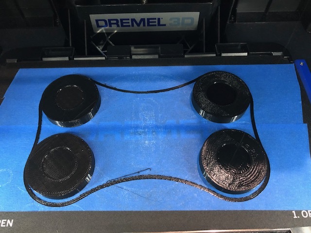
Extrude the inner part of wheels with the height of 9mm. You only extruded 2 wheels, so you need to double it because there are 4 wheels for the forklift. To do so, copy the 2 wheels that you just extruded previously and move it. Save it to STL file. Print it.
Extrude Forklift Body
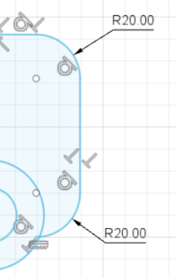
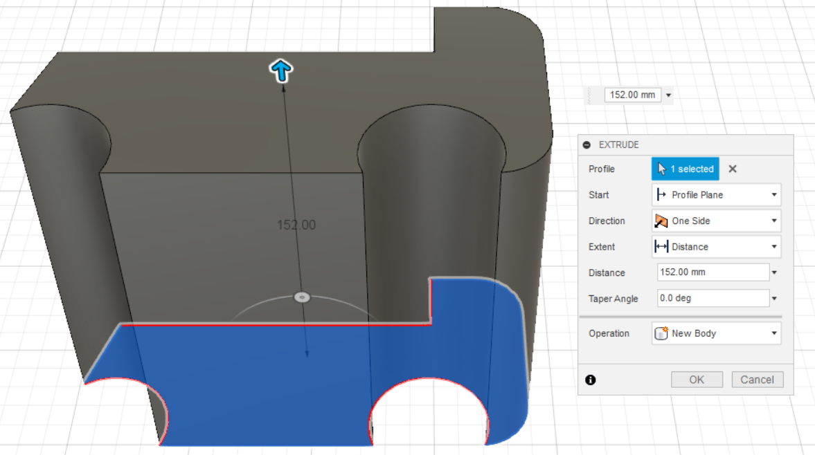
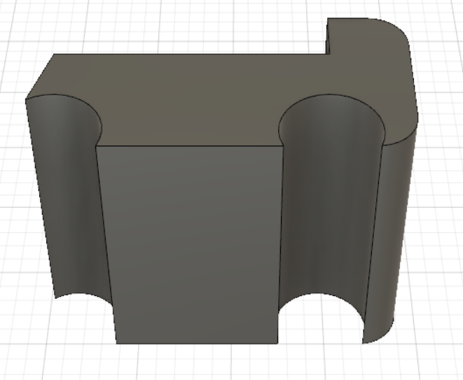
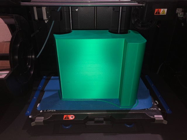
For the forklift body, bevel the corner of the body. In order to bevel, use the Fillet button in the Sketch Mode. Adjust the bevel as you desire. Here, I used 20 mm of bevel. See the picture. Extrude the forklift body for 152 mm of height. Save it to STL file. Print it.
Extrude Overhead Guard and the Supports
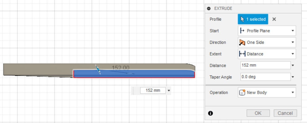
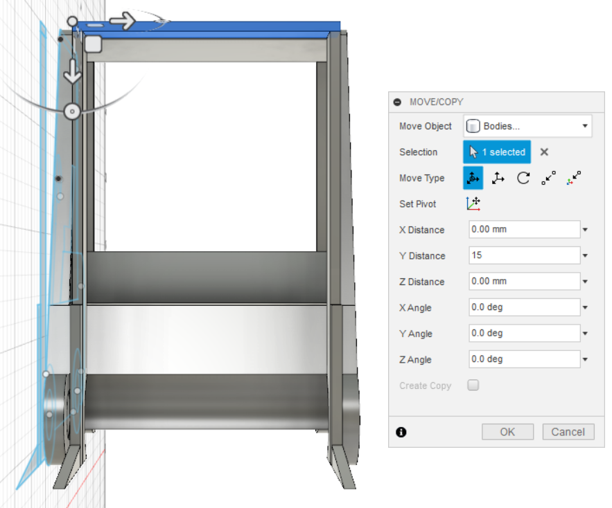
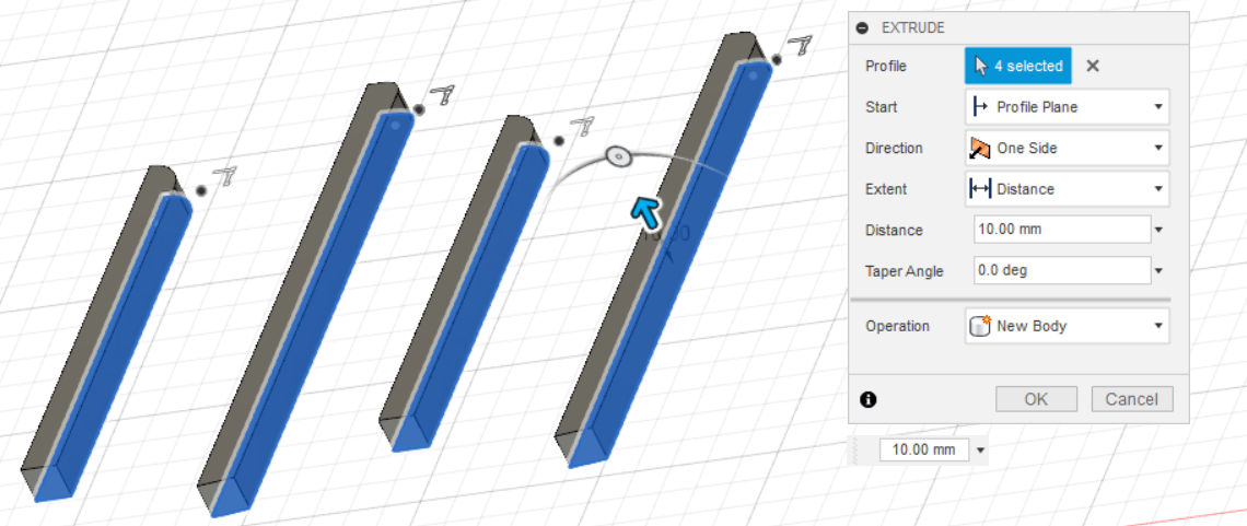
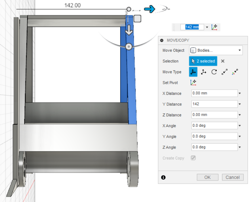
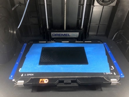
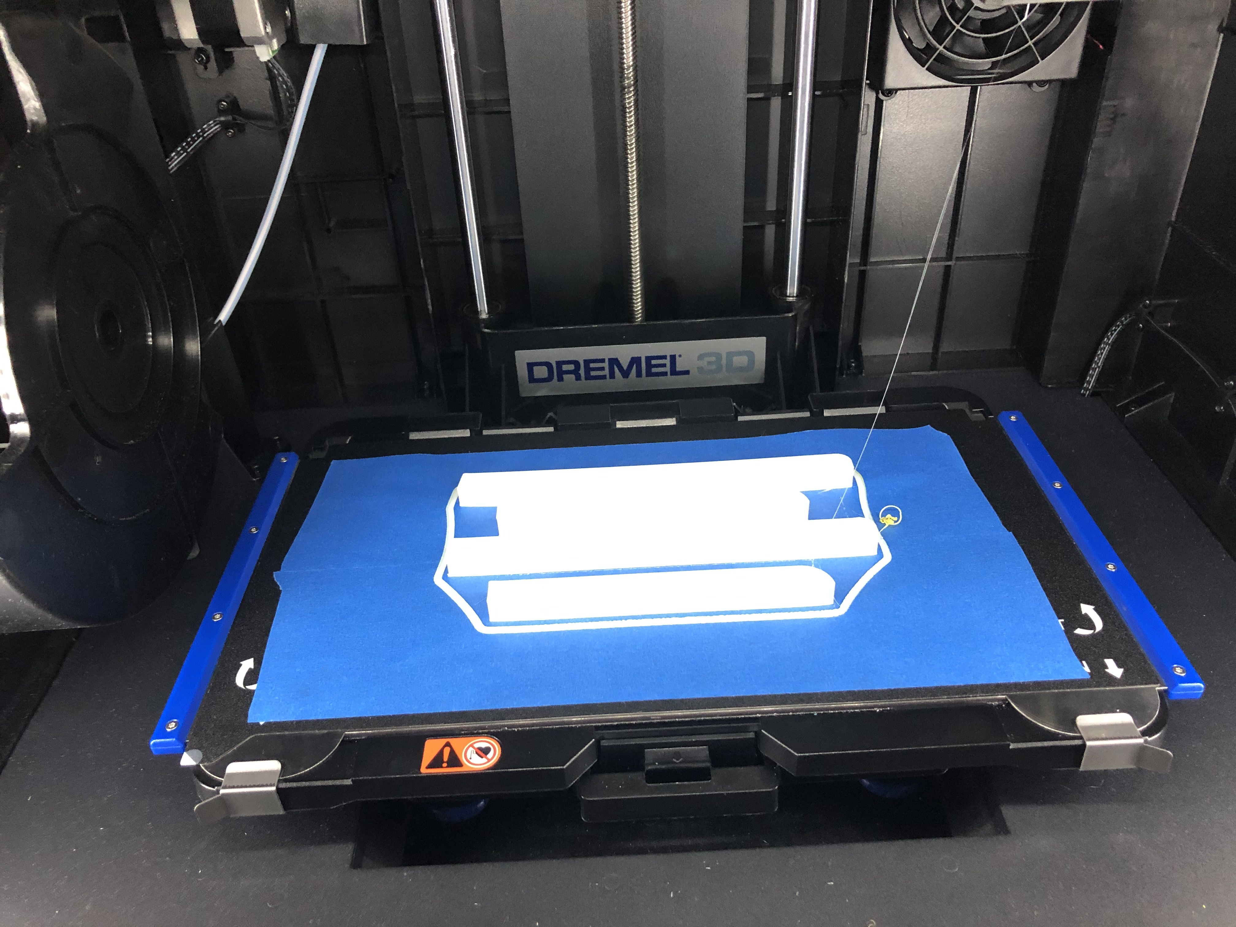
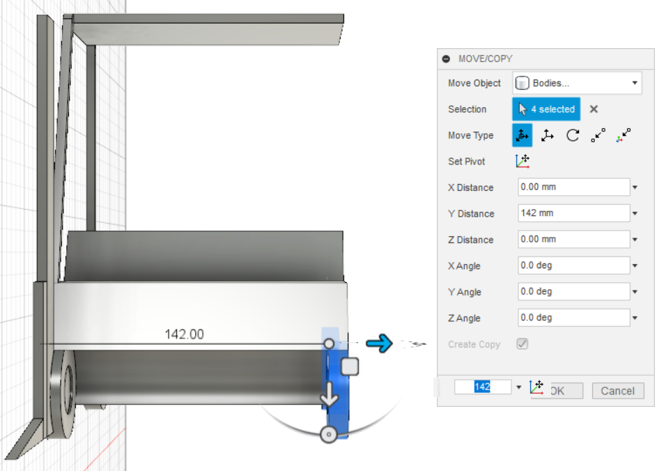
For the overhead guard, bevel the corner of the roof. Adjust the bevel as you desire. I used 5 mm and 10 mm of bevel on the left and the right, respectively. In addition, add some more lines for becoming the thickness of the overhead guard by using sketch mode. After that, extrude it for 152 mm of height. For the supports, extrude them to the thickness of 10 mm. Because now the supports are only 2, make a copy by selecting both of them and translate them about 142 mm to the right. Now you have 4 supports. For more details, see the picture. Save it to STL file. Print it. I choose black color for the overhead guard and white for the supports.
Extrude Forklift Mast
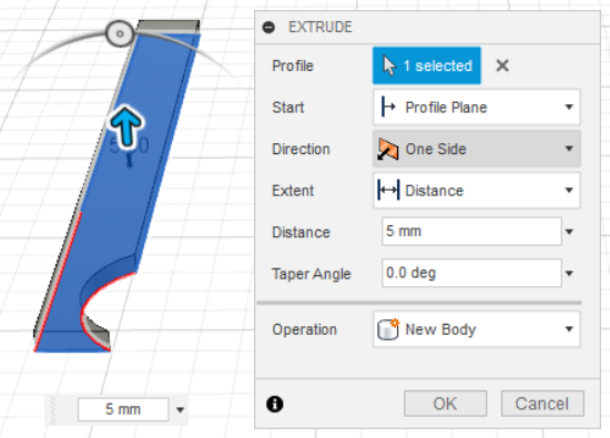
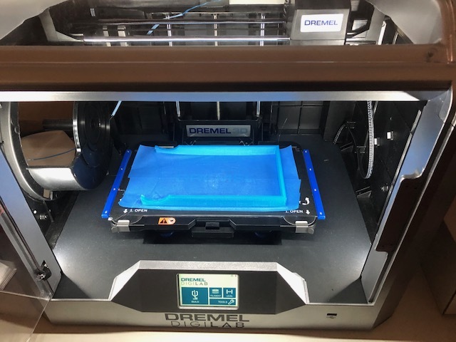
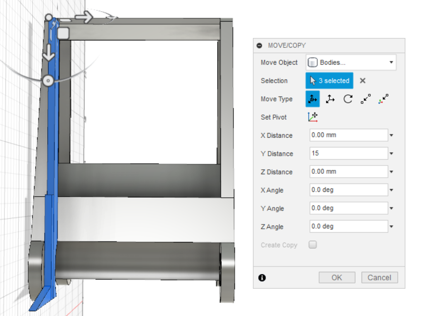
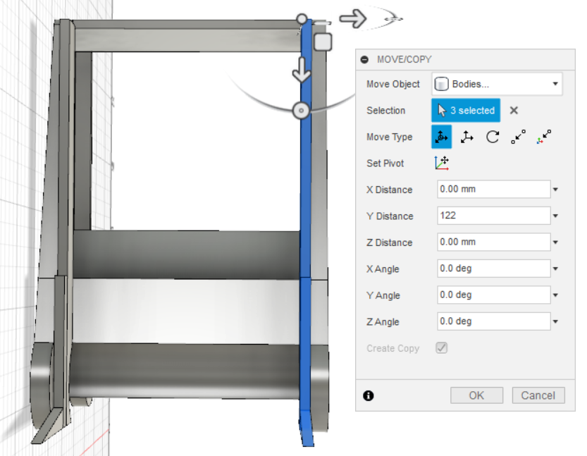
Extrude forklift mast for about 5 mm thickness. Then, save it to STL file. Print it. I chose see-through blue for the color.
Extrude Forklift Load Backrest
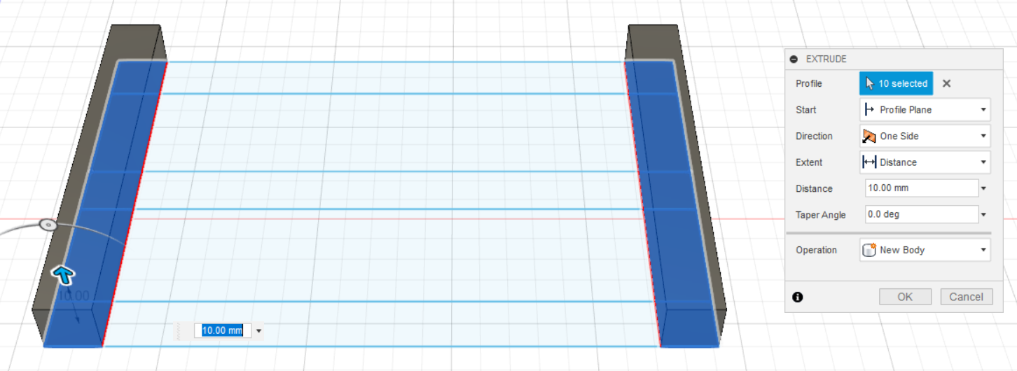
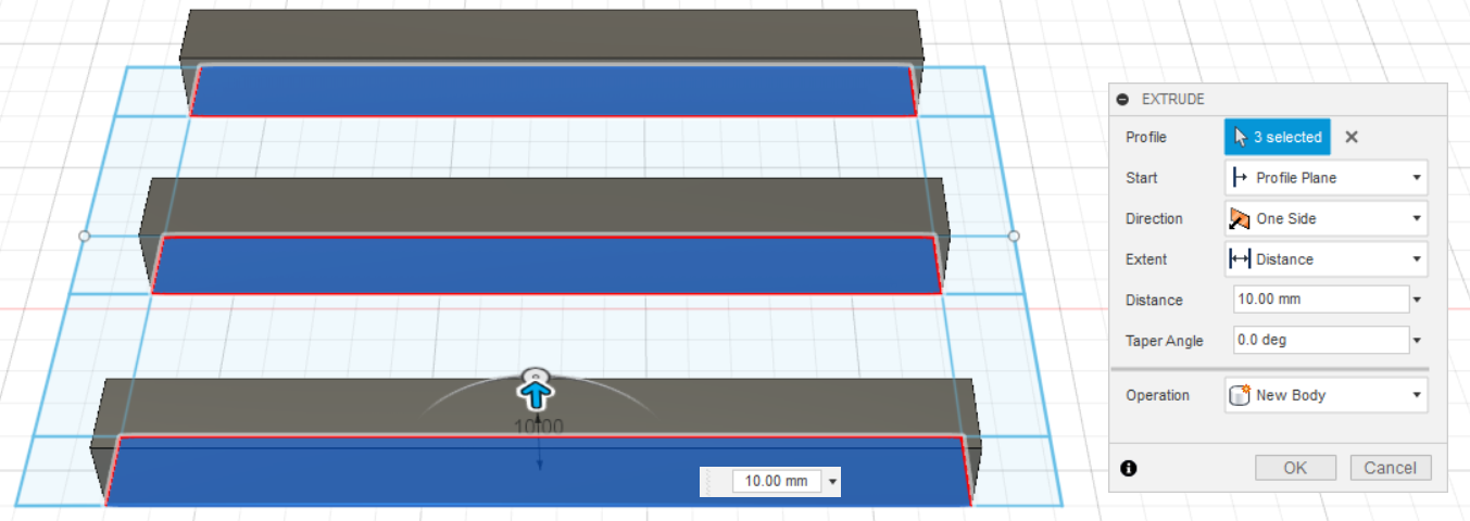
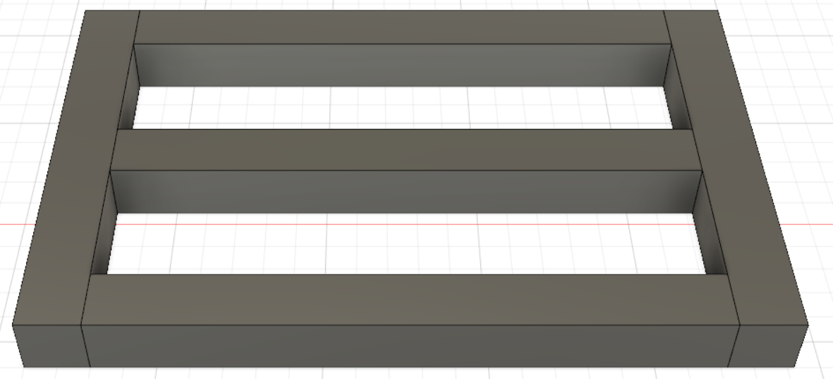
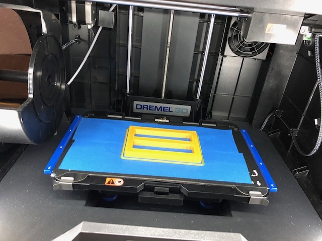
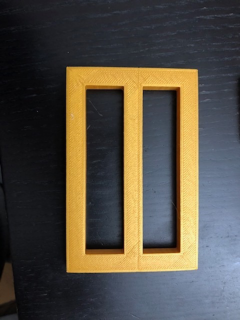
Extrude Load Backrest for about 10 mm thick for each body one by one, and save it to STL file. Print it.
Extrude Forklift Forks

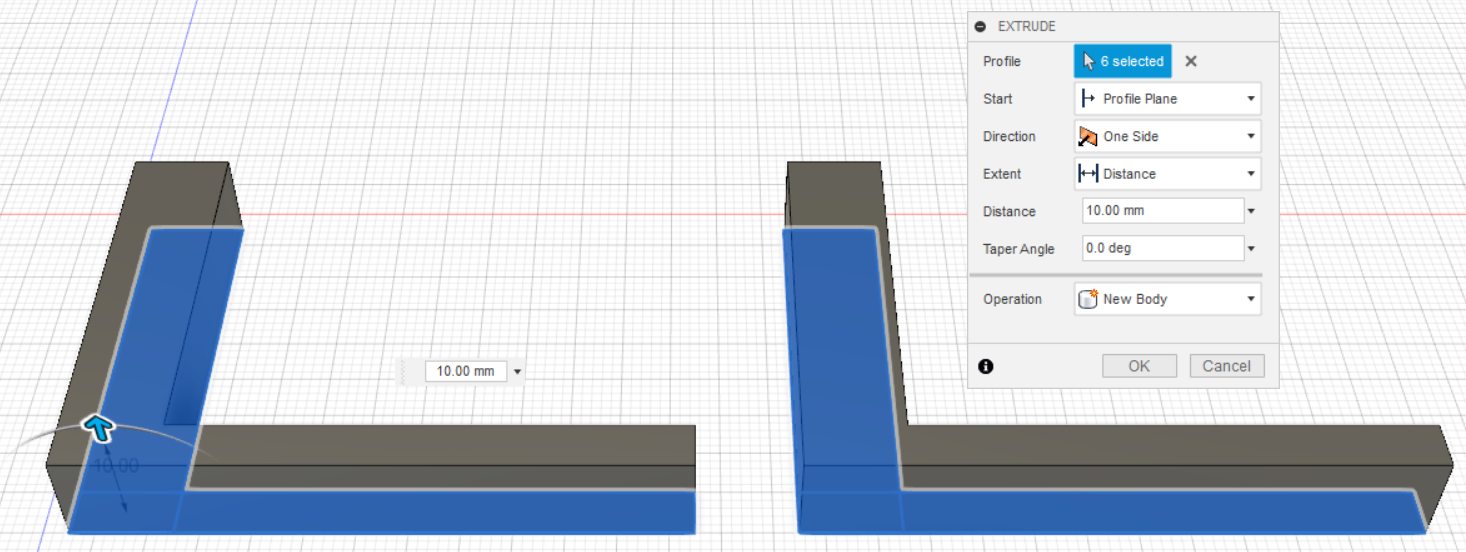

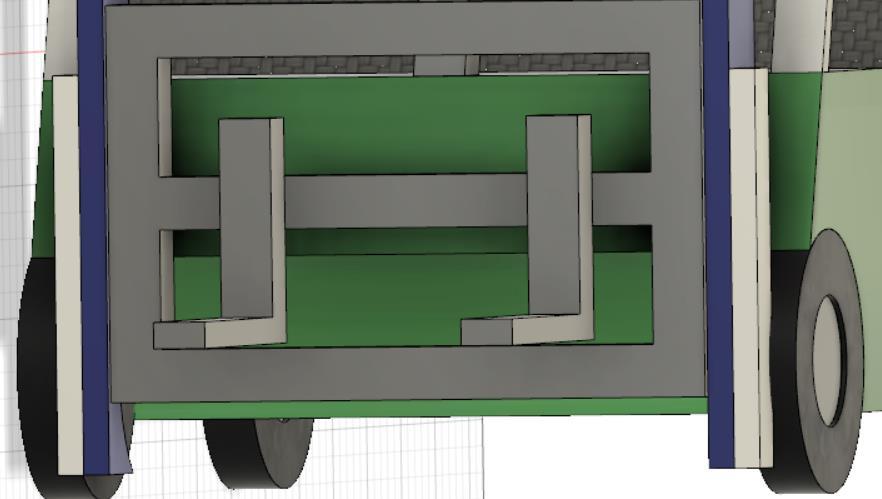
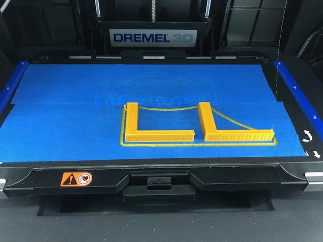
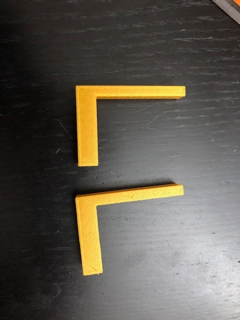
Extrude the Forks for about 10 mm thick for each body one by one, and save it to STL file. Print it.
Extrude Forklift Engine/Battery Compartment
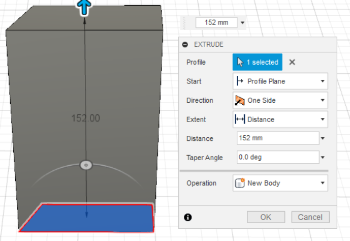
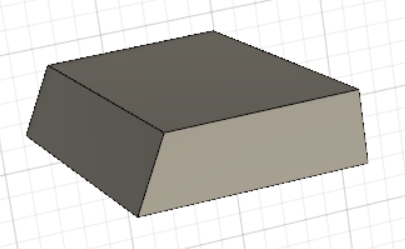
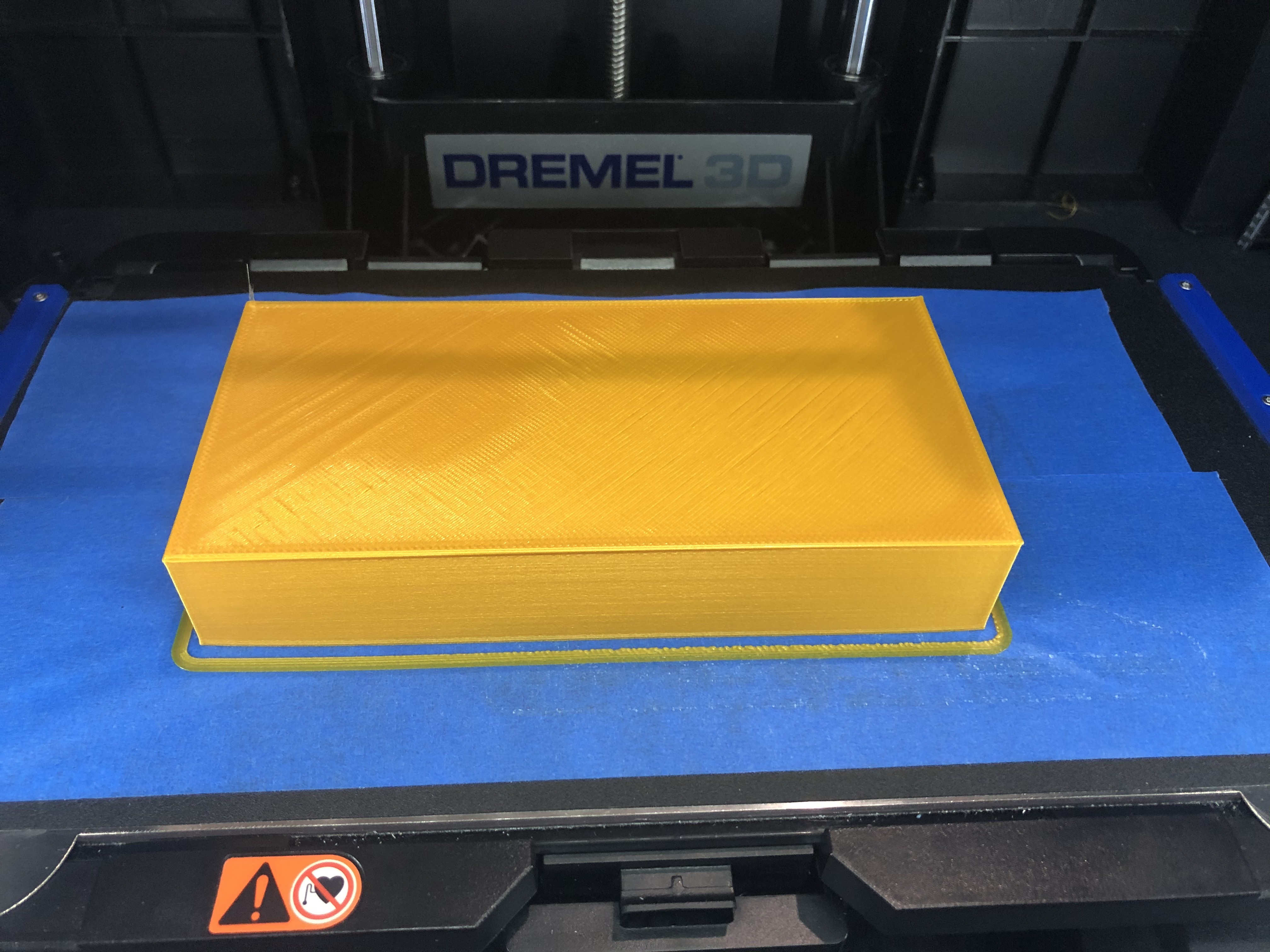
Extrude the Forklift Engine/Battery Compartment for 152 mm of thickness. (It must be the same as the width of the forklift body). Save it to STL file. Print it. I chose light gold color for this. You can choose the color as you desire.
Extrude Seat
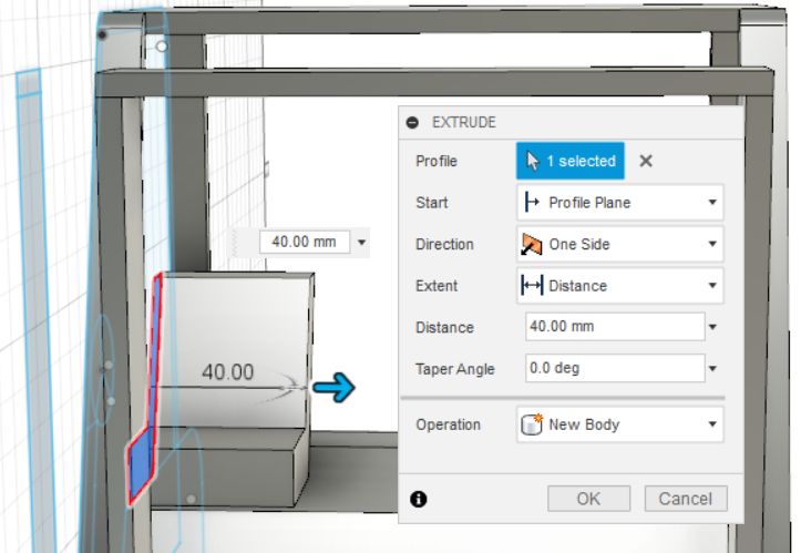
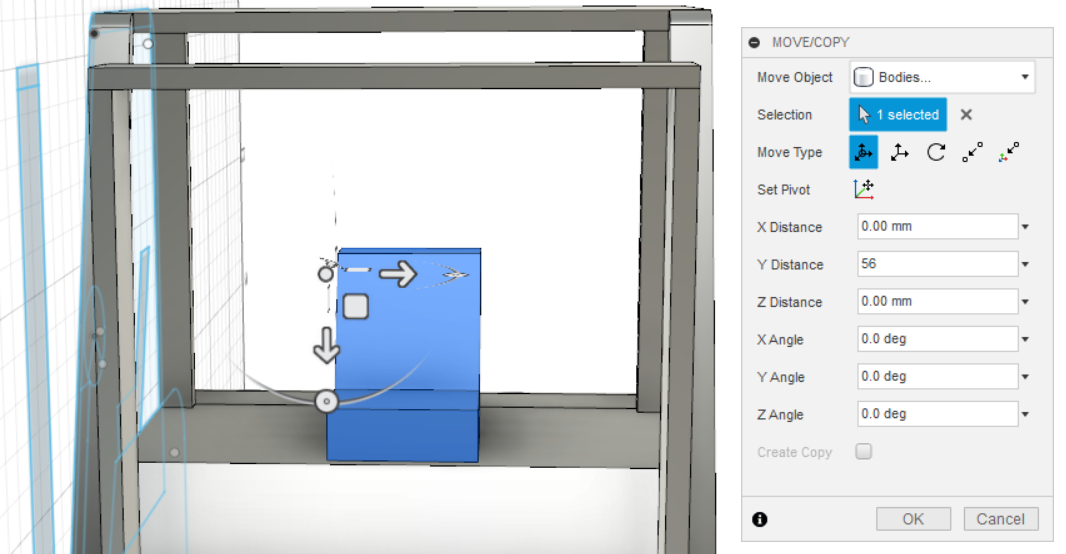
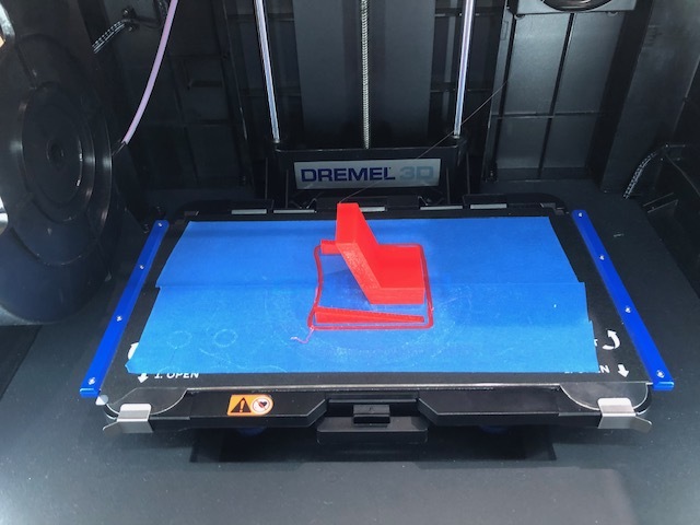
Extrude it for thickness of 40 mm. Move it to the center with a y-distance of 56 mm. Save it to STL file. Print it. I use red color for the seat. You can choose whatever color you like.
Extrude Steering Wheel
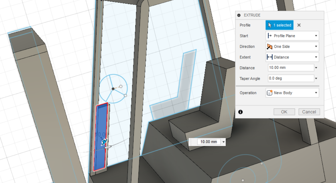
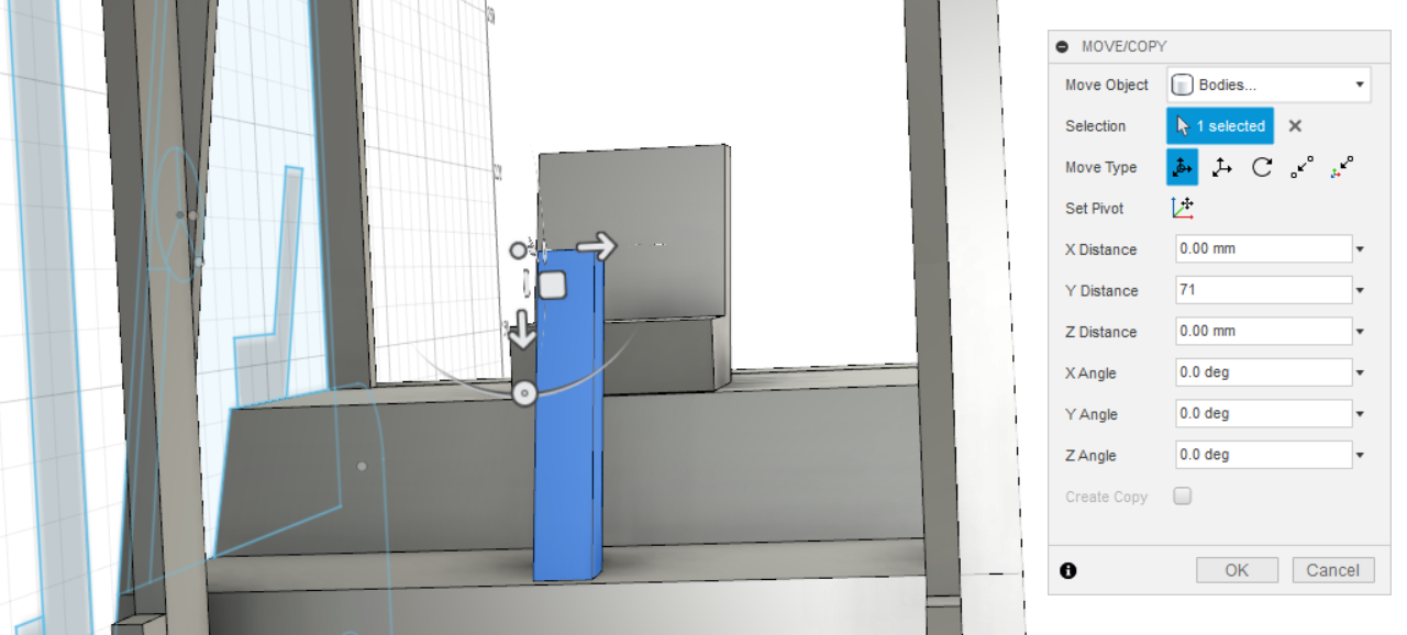
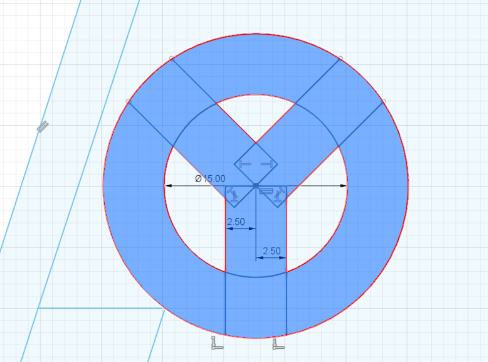
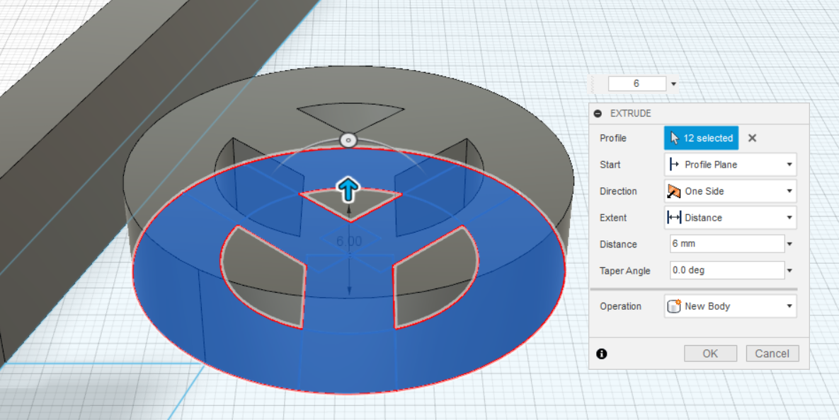
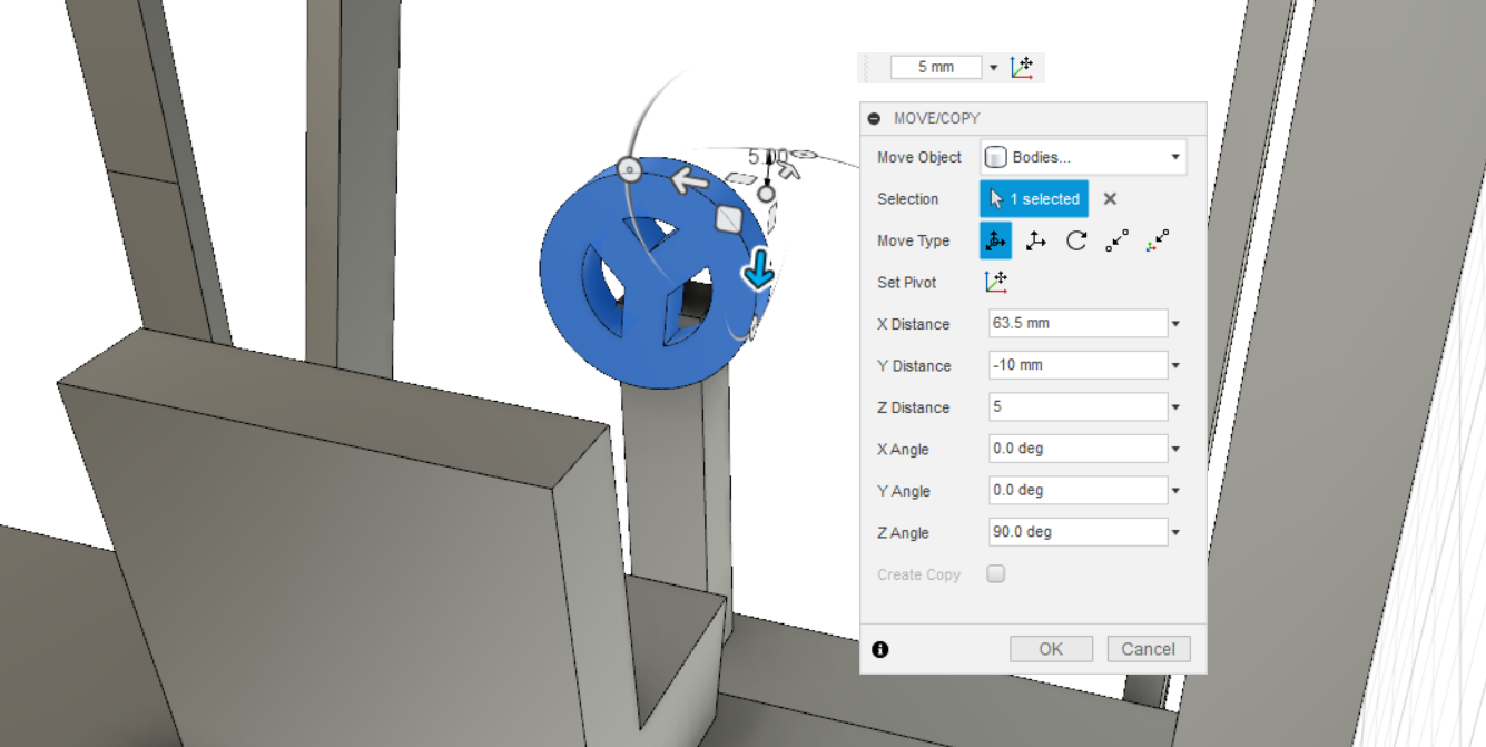
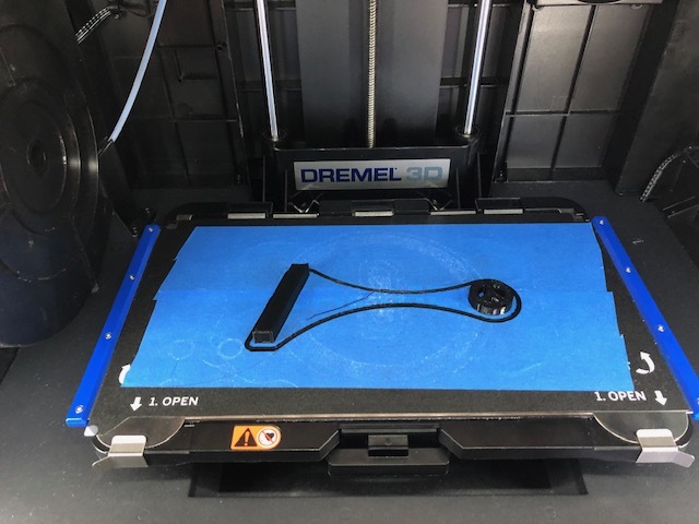
Extrude the Steering Wheel and its support with a thickness of 10 mm and save it to STL file. Print it. I choose the color of black for the steering wheel.
Assemble Clock – Pt. 1
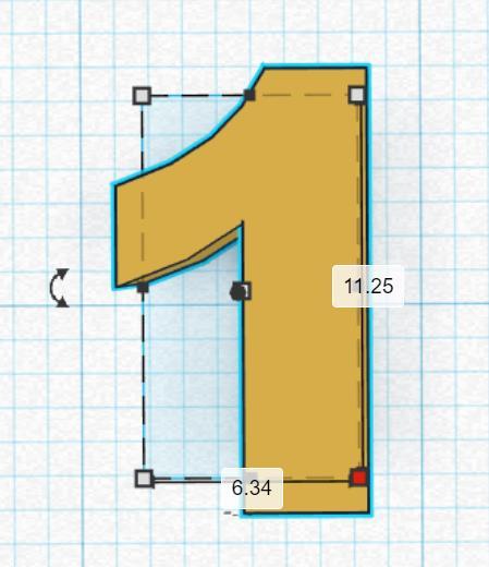
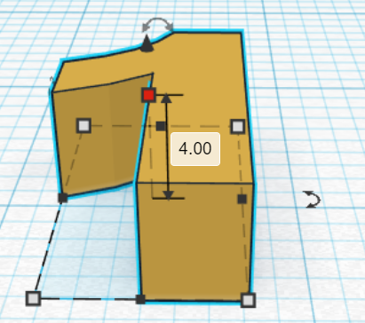
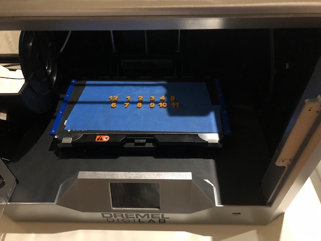
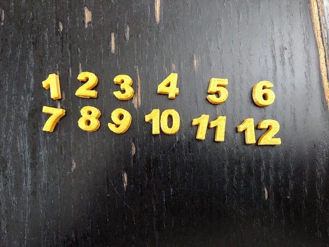
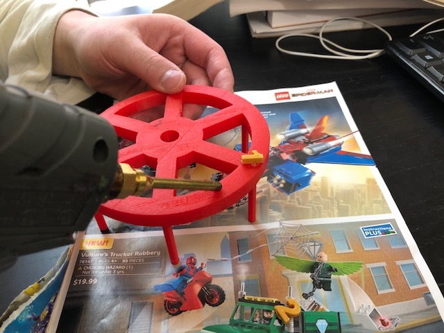
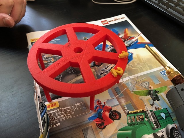
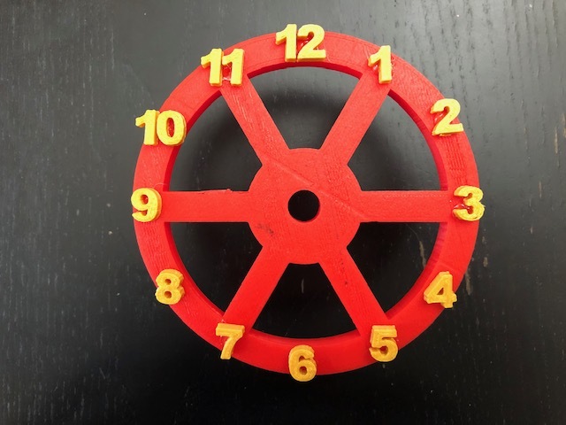
Make numbers of the clock in Tinkercad because it is easier making numbers in Tinkercad by clicking "Text and Numbers". Choose the numbers. Make them from 1 to 12. (Length: 11.25 mm, Width: 6.34 mm, and Height: 4 mm) If you want to see my Tinkercad numbers, click here. Save and export them to STL file. Print them. Glue the numbers of the Clock Wheel frame.
Assemble Clock – Pt. 2
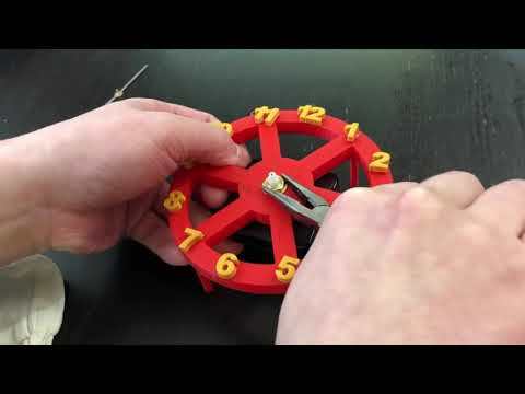
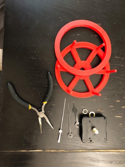
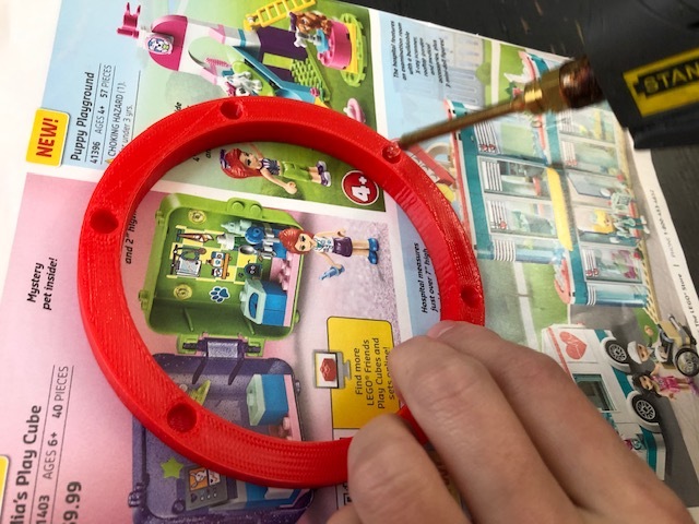
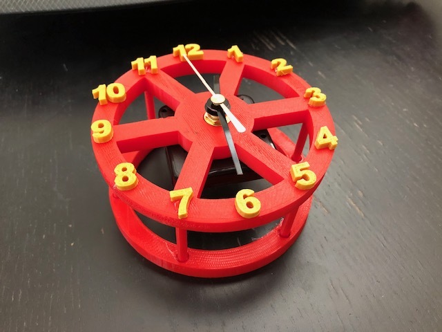
Install the clock mechanism to the body of the Clock Wheel frame. Information regarding how to install the clock mechanism is shown in the video. Just make sure the orders of the clock mechanism installment, which are quartz, washer, nut, hour hand, minute hand, and second hand. I cut the hour hand, minute hand, and second hand because they are too long to be attached to the clock wheel. Glue the back part of the clock wheel, so they are attached to each other with the front part. See pictures.
Assemble Forklift – Pt. 1
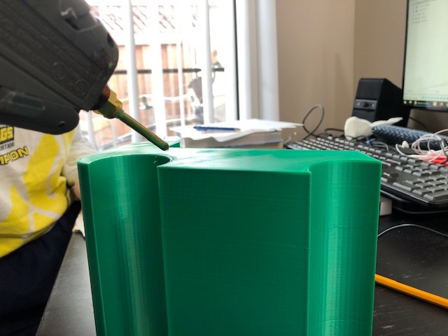
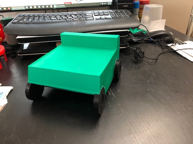
Glue the wheels to the body.
Assemble Forklift – Pt. 2
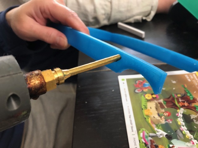
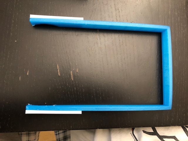
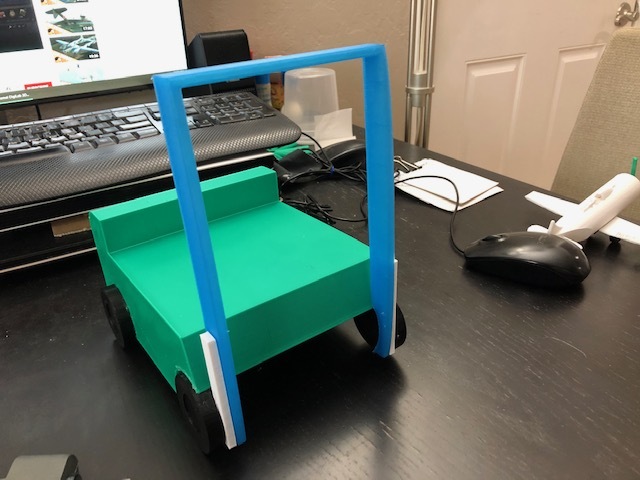
Glue the mast to the body.
Assemble Forklift – Pt. 3
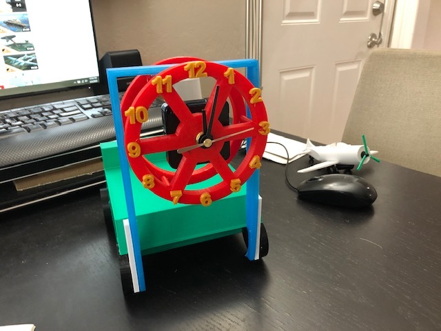
Attach the Clock Wheel to the mast of the Forklift by using hot glue.
Assemble Forklift – Pt. 4
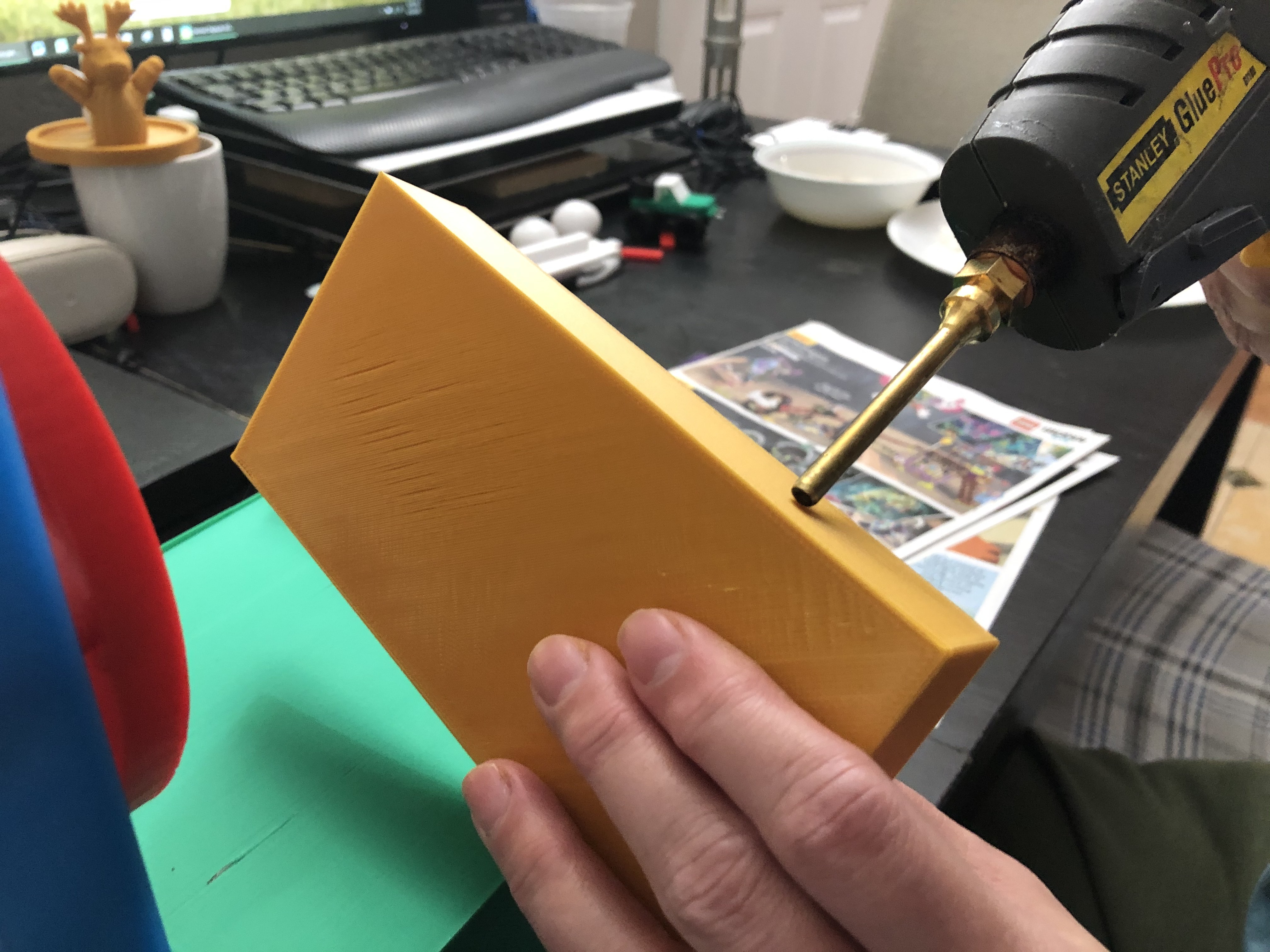
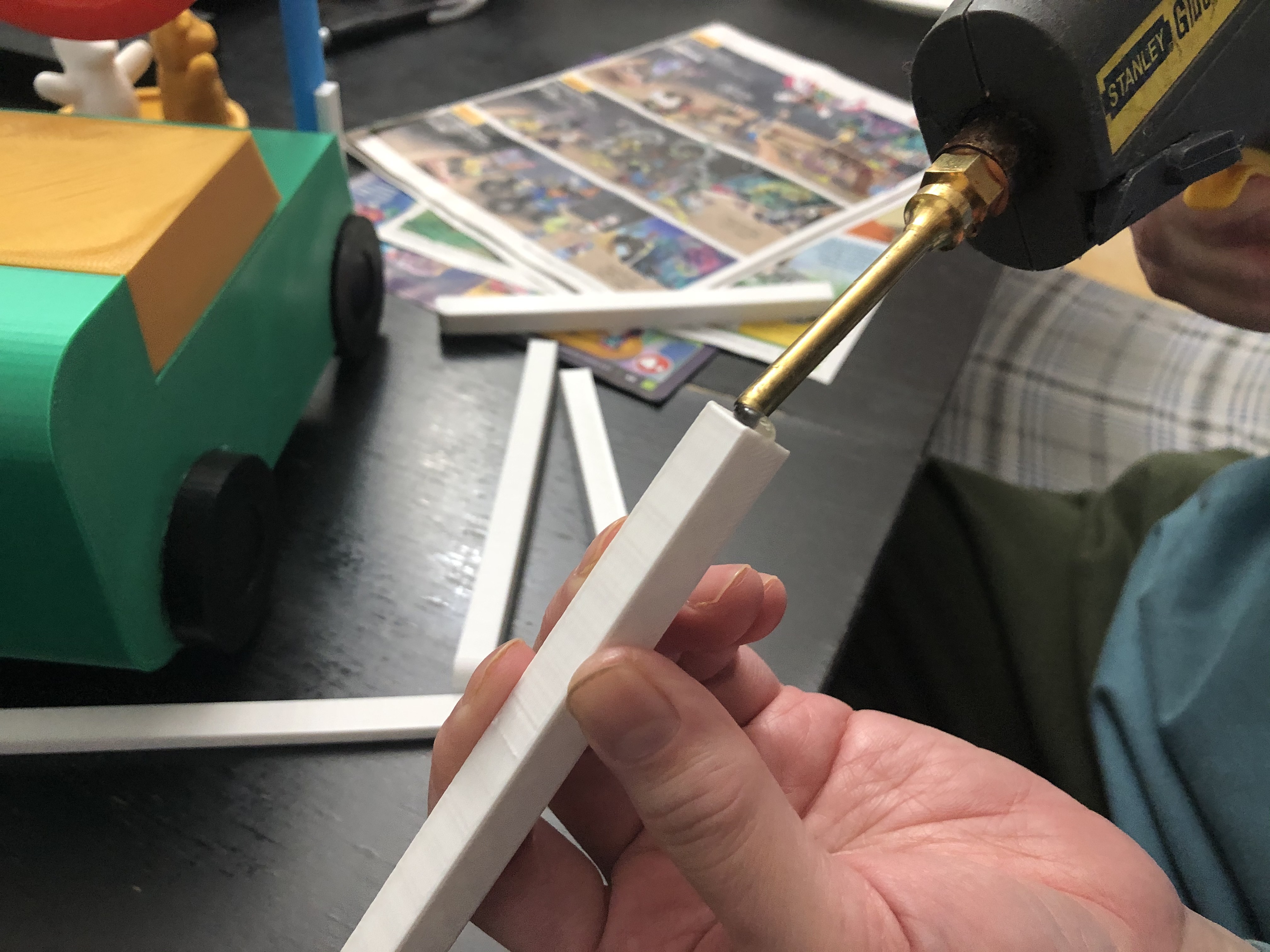
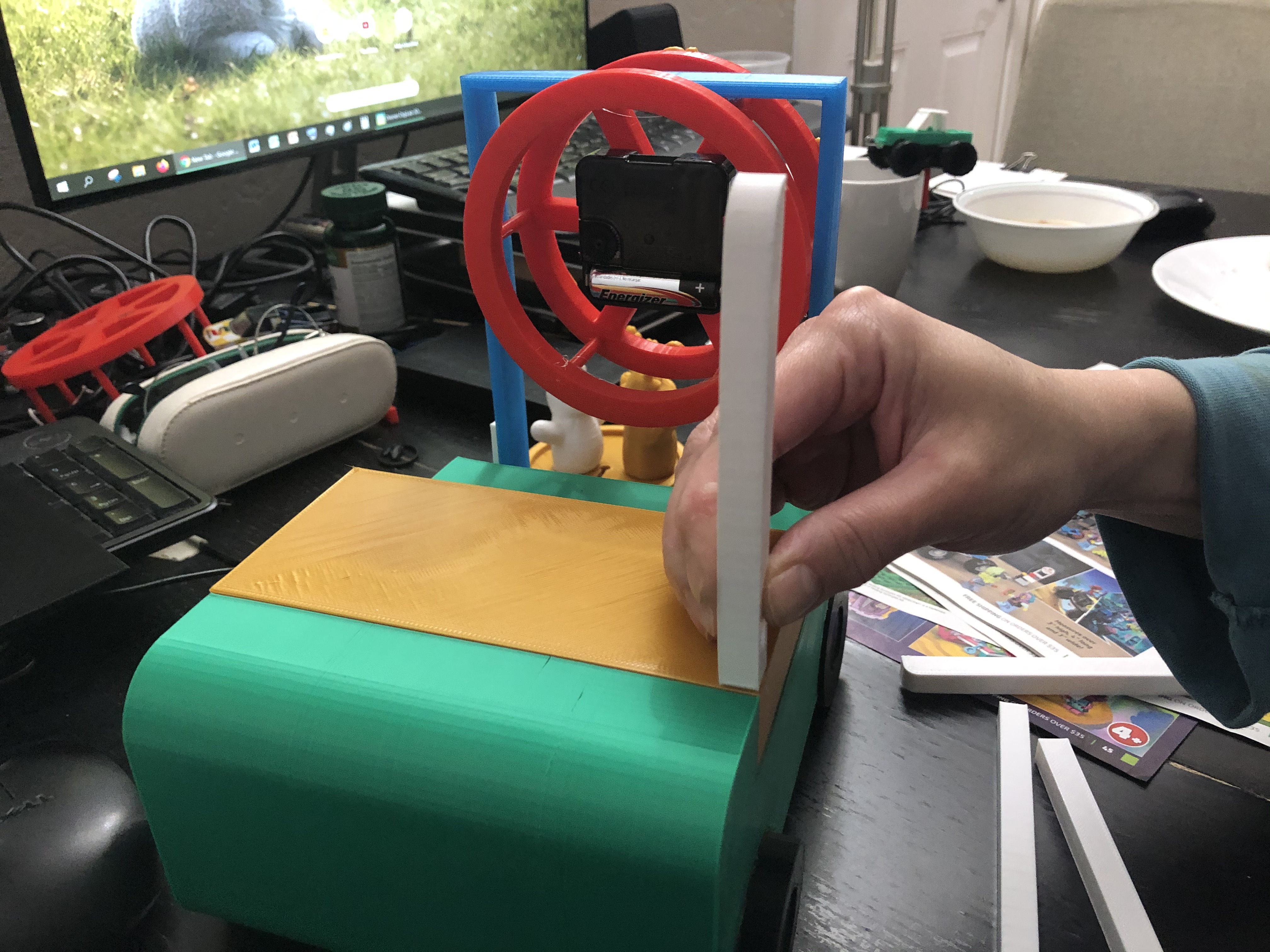
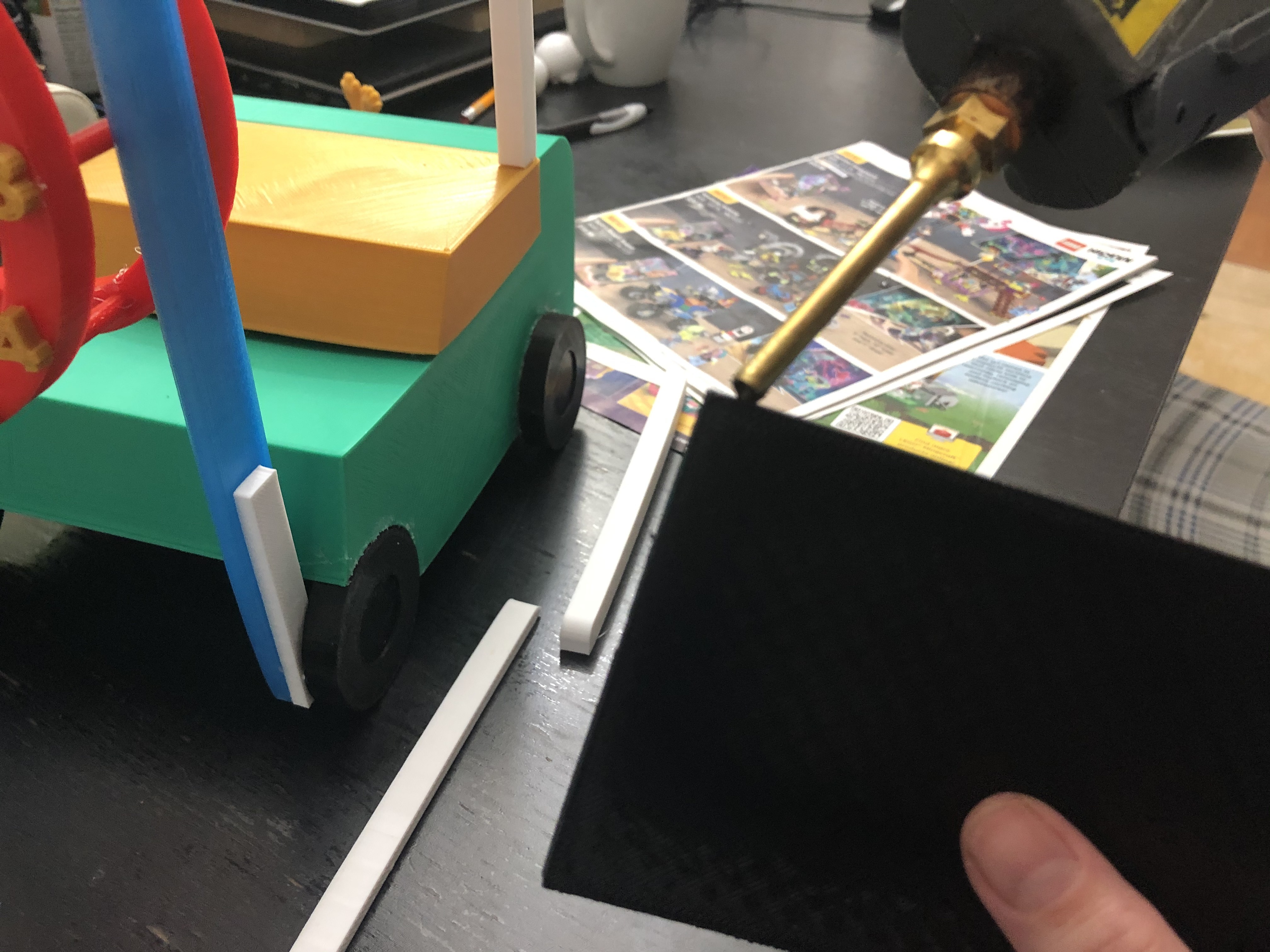
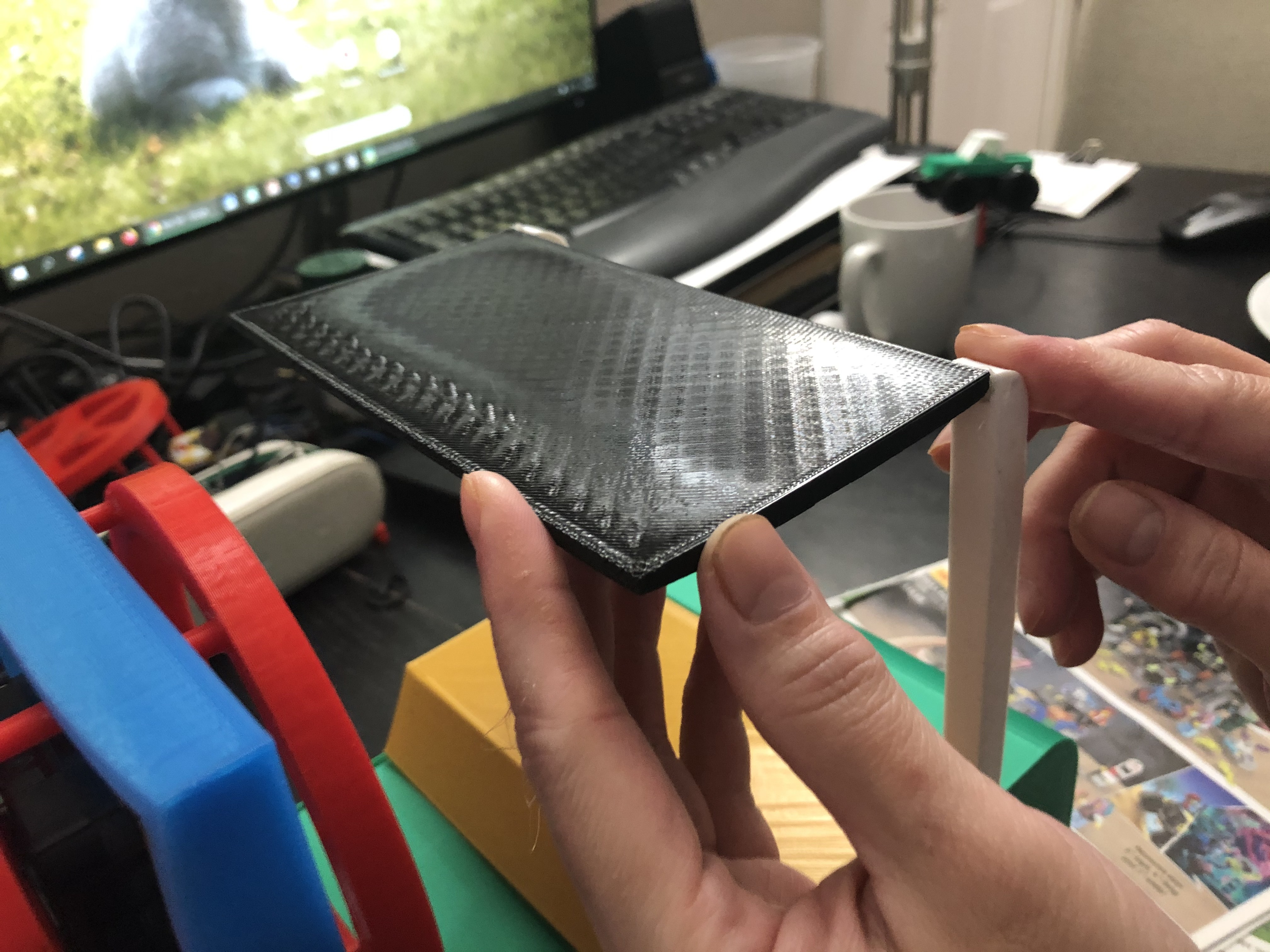
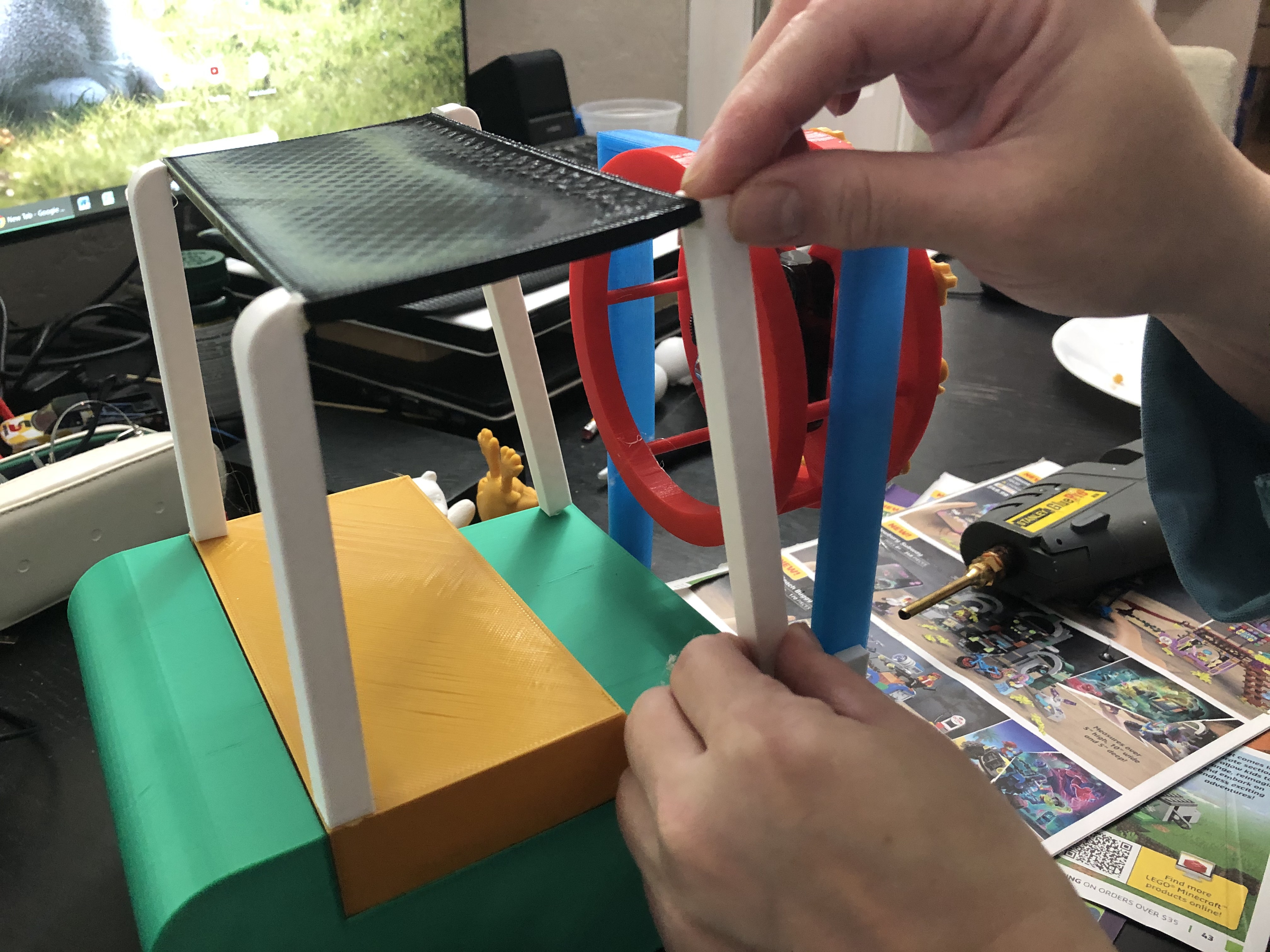
Glue the engine of battery compartment to the body. Next, attach the overhead guard and its supports.
Assemble Forklift – Pt. 5
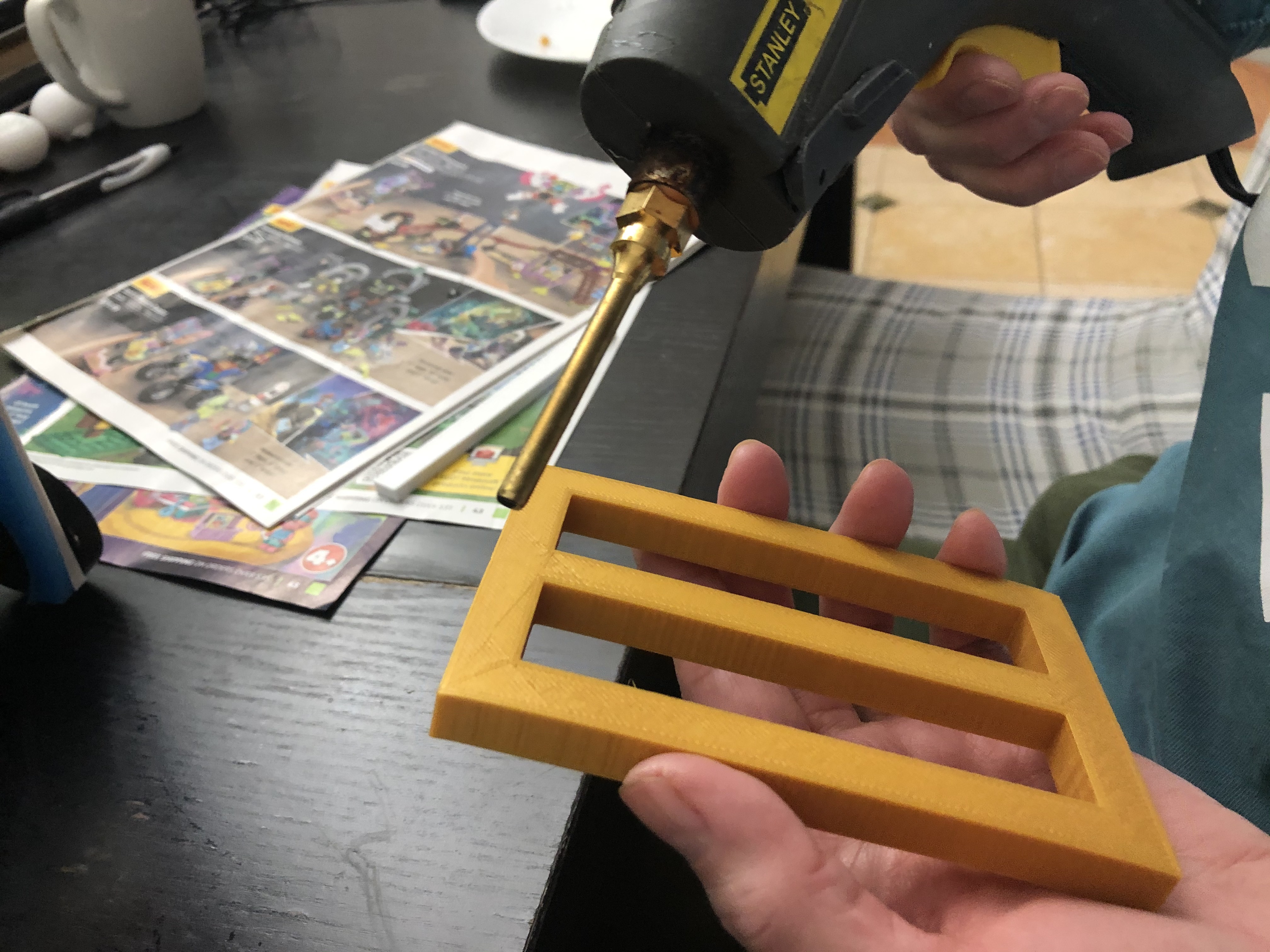
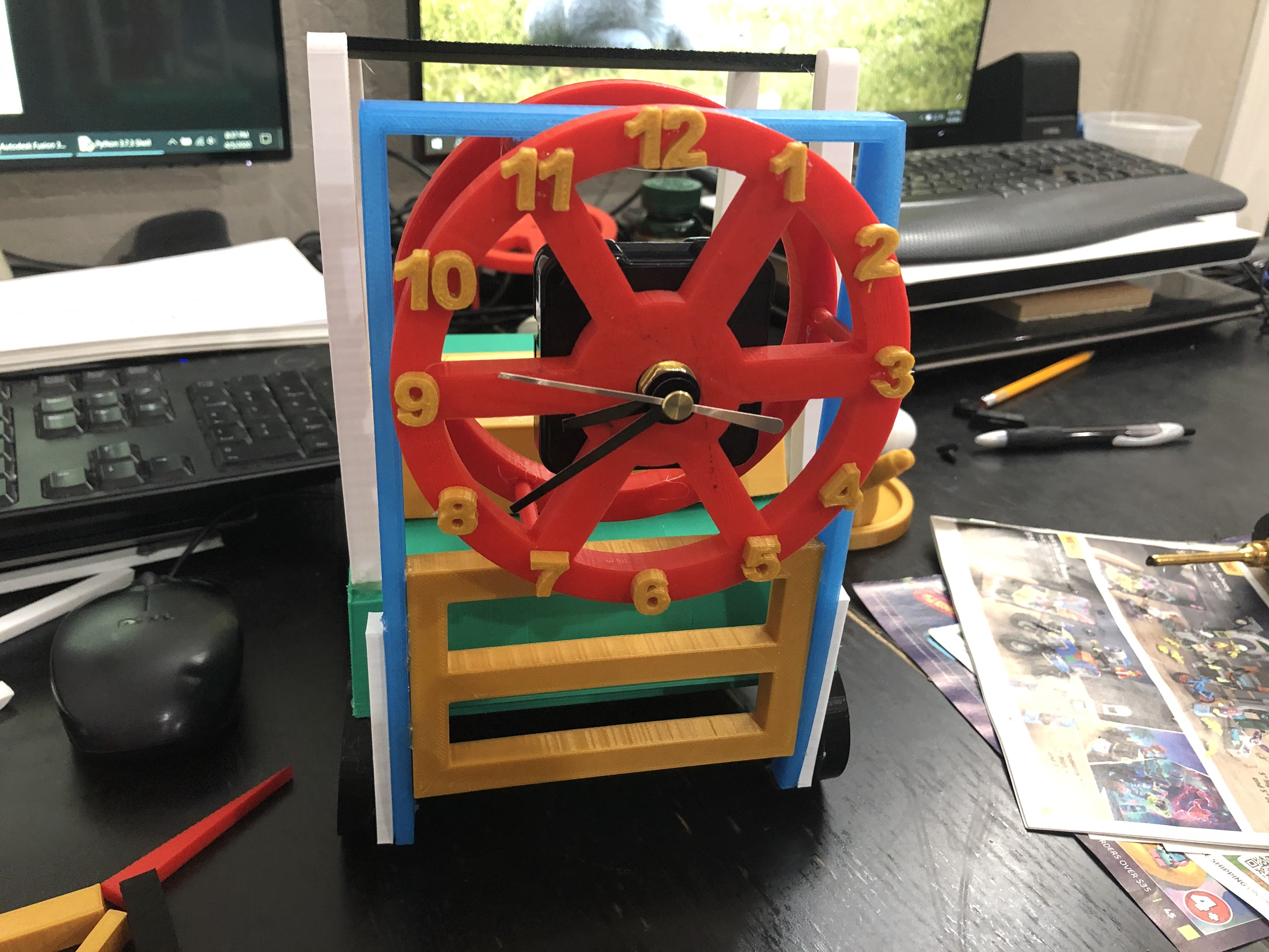
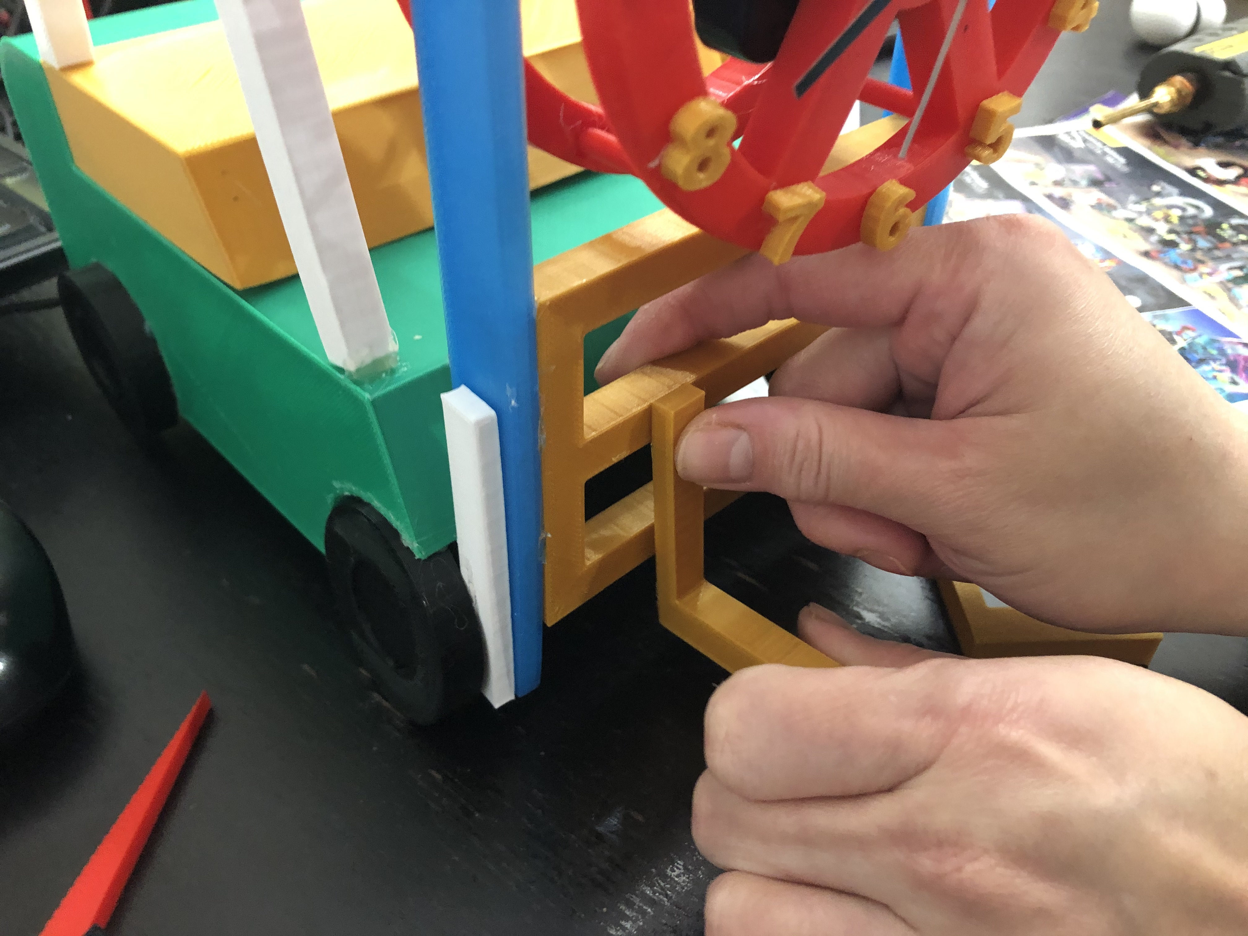
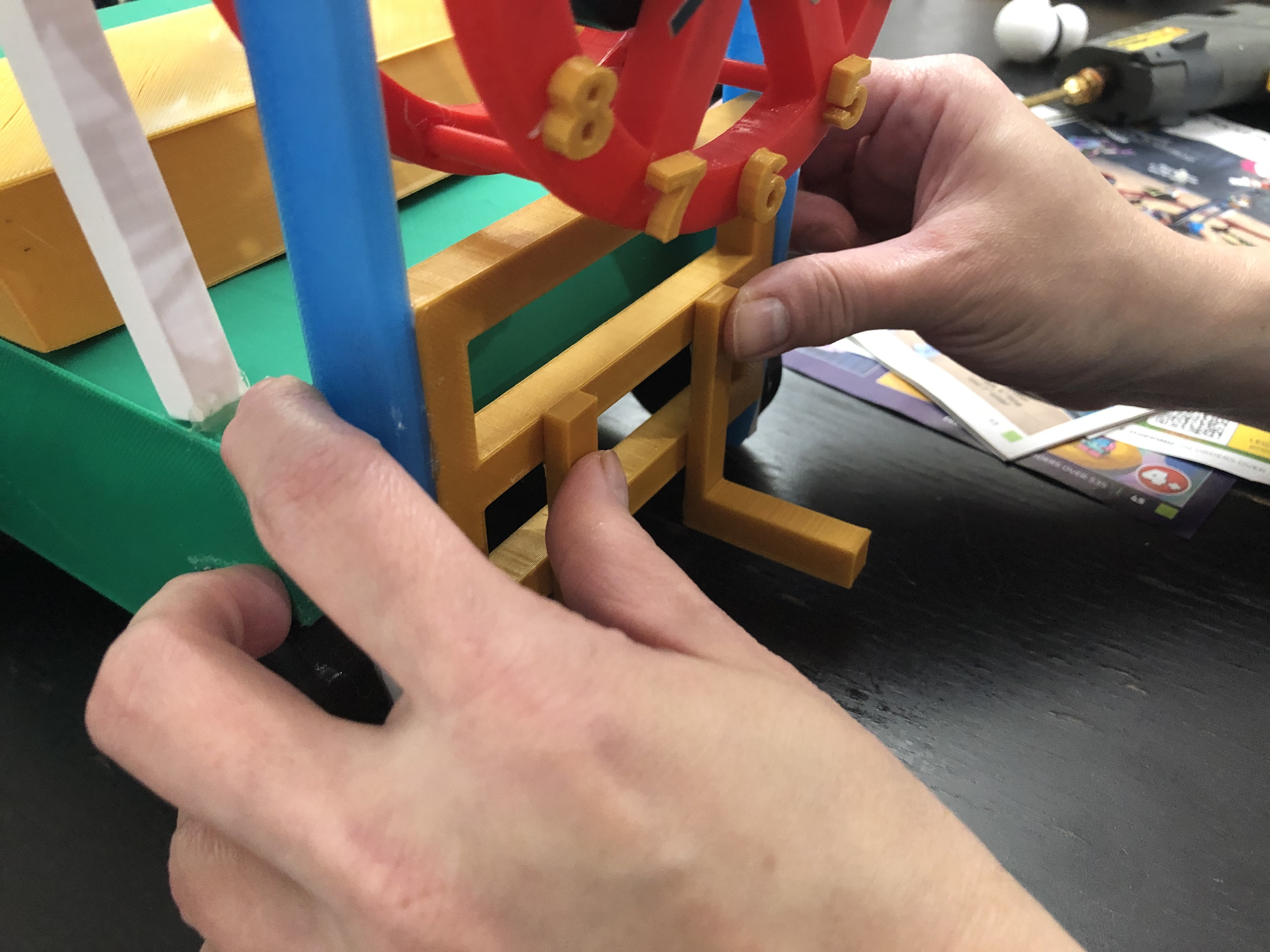
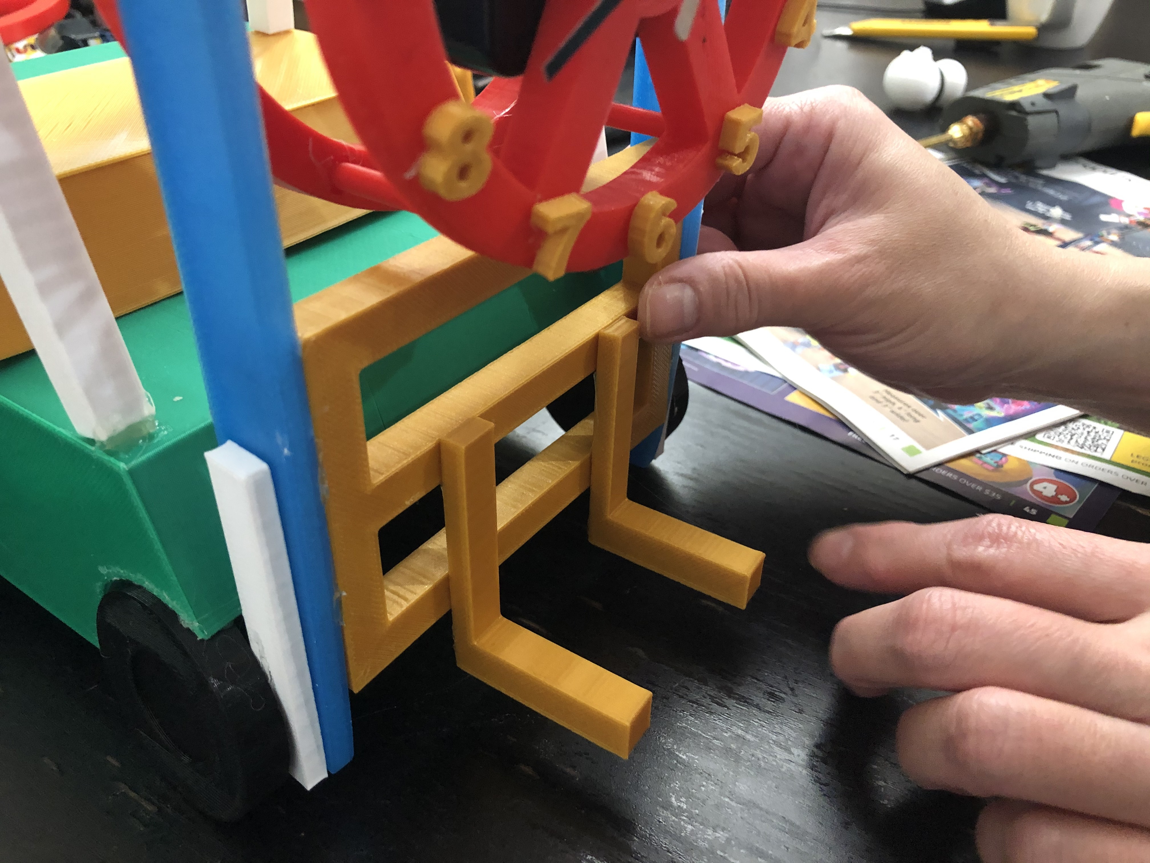
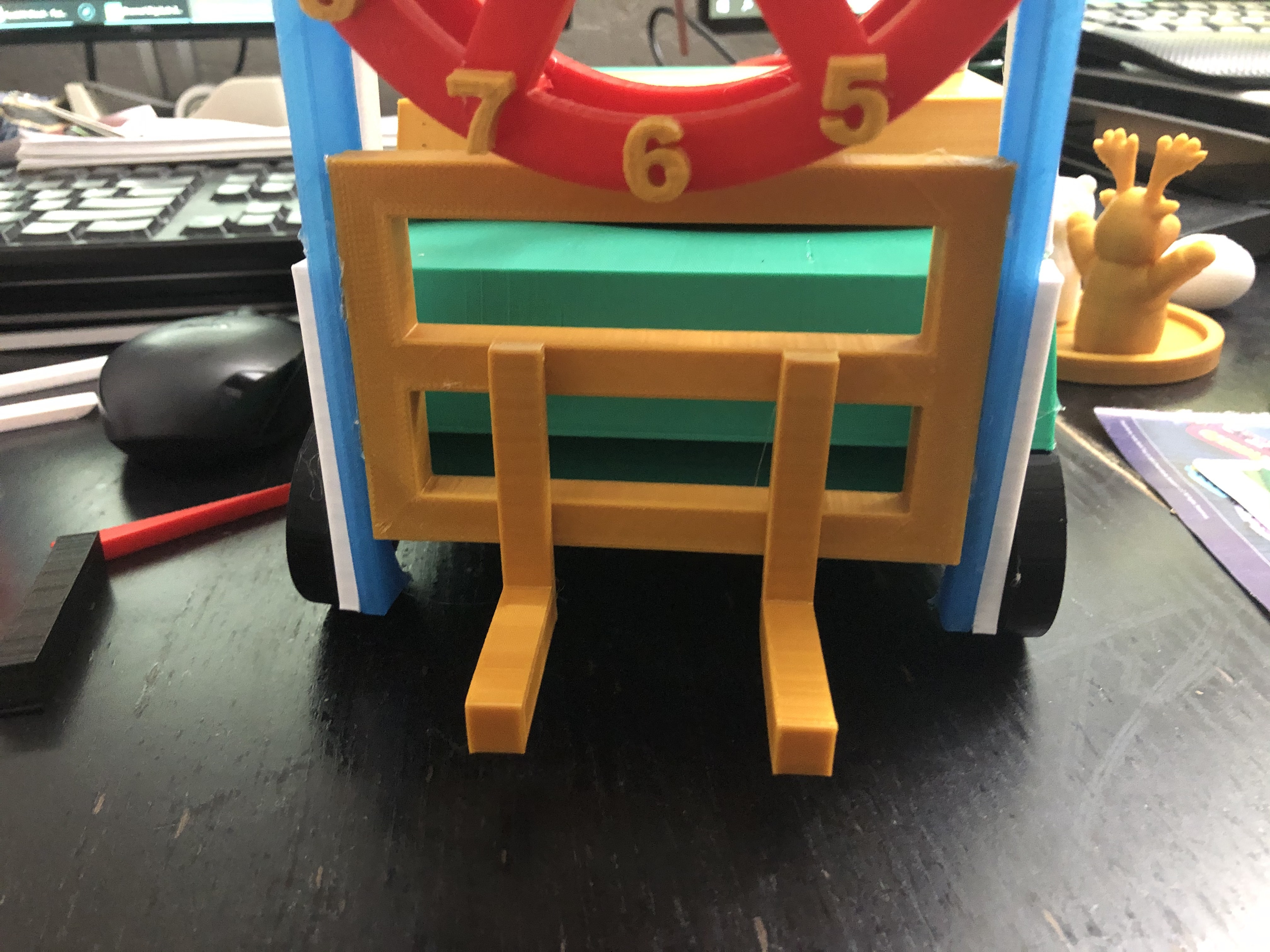
Attach the Load Backrest to the mast. Next, glue the forks to the backrest.
Assemble Forklift – Pt. 6
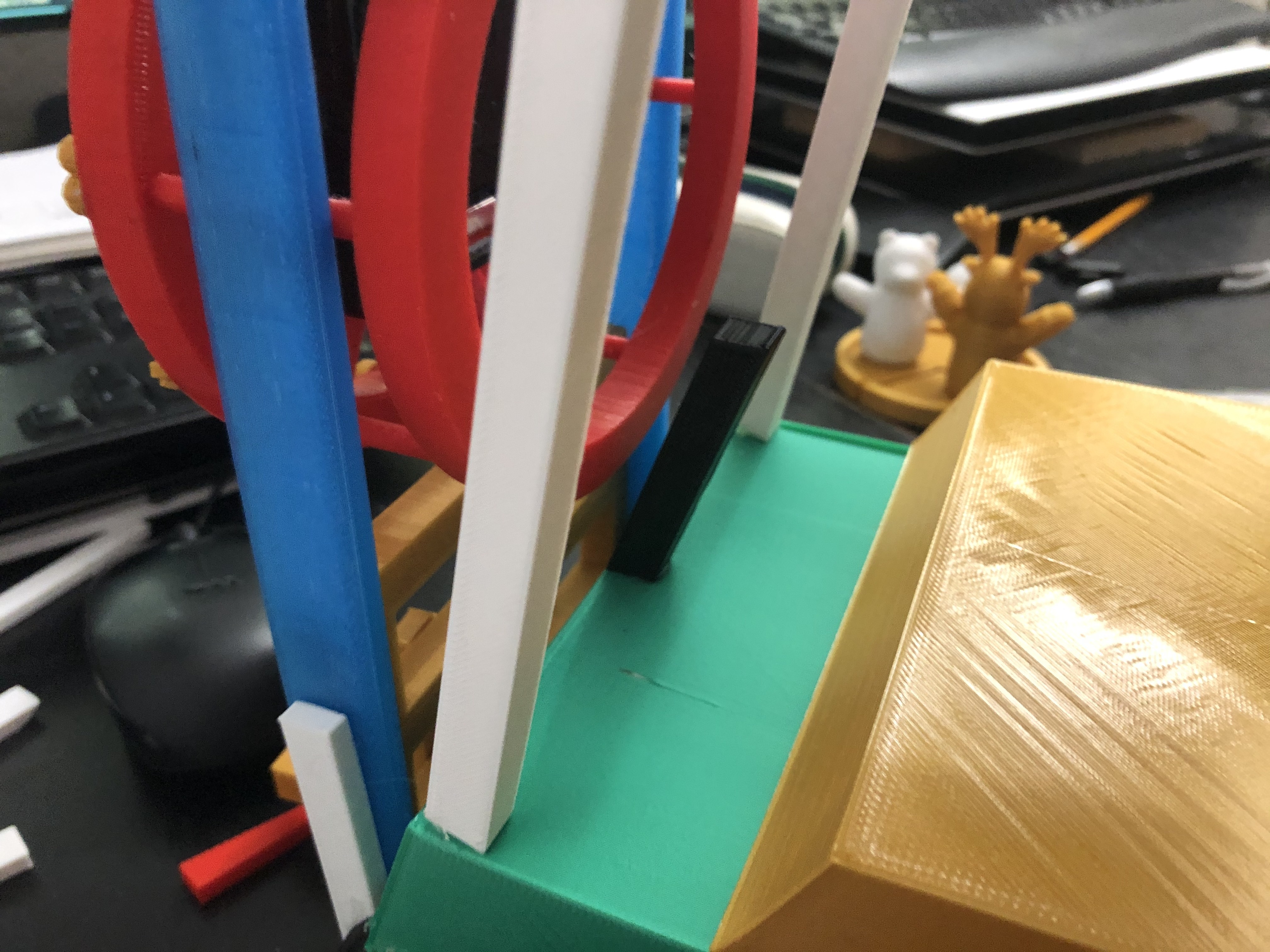
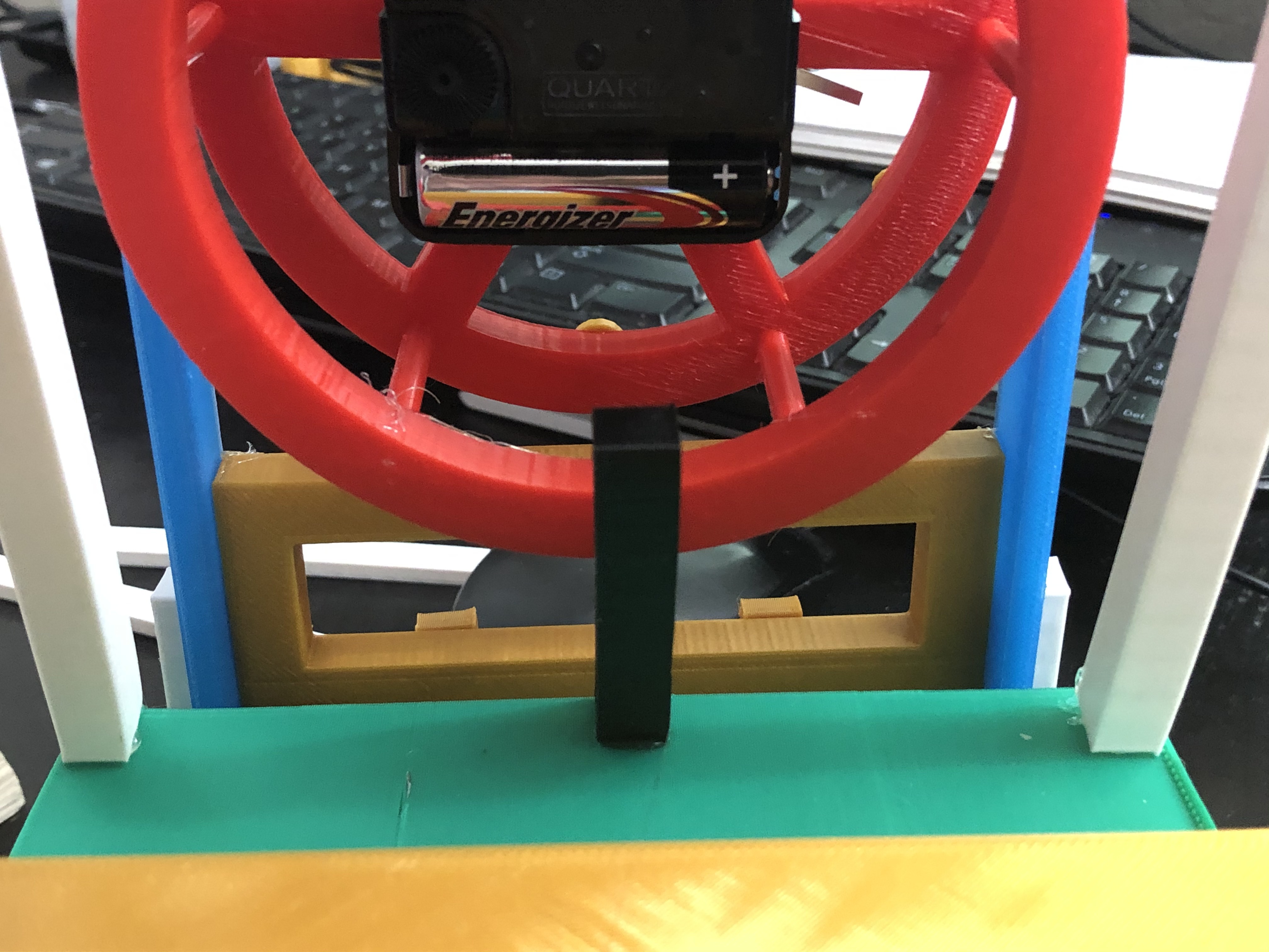
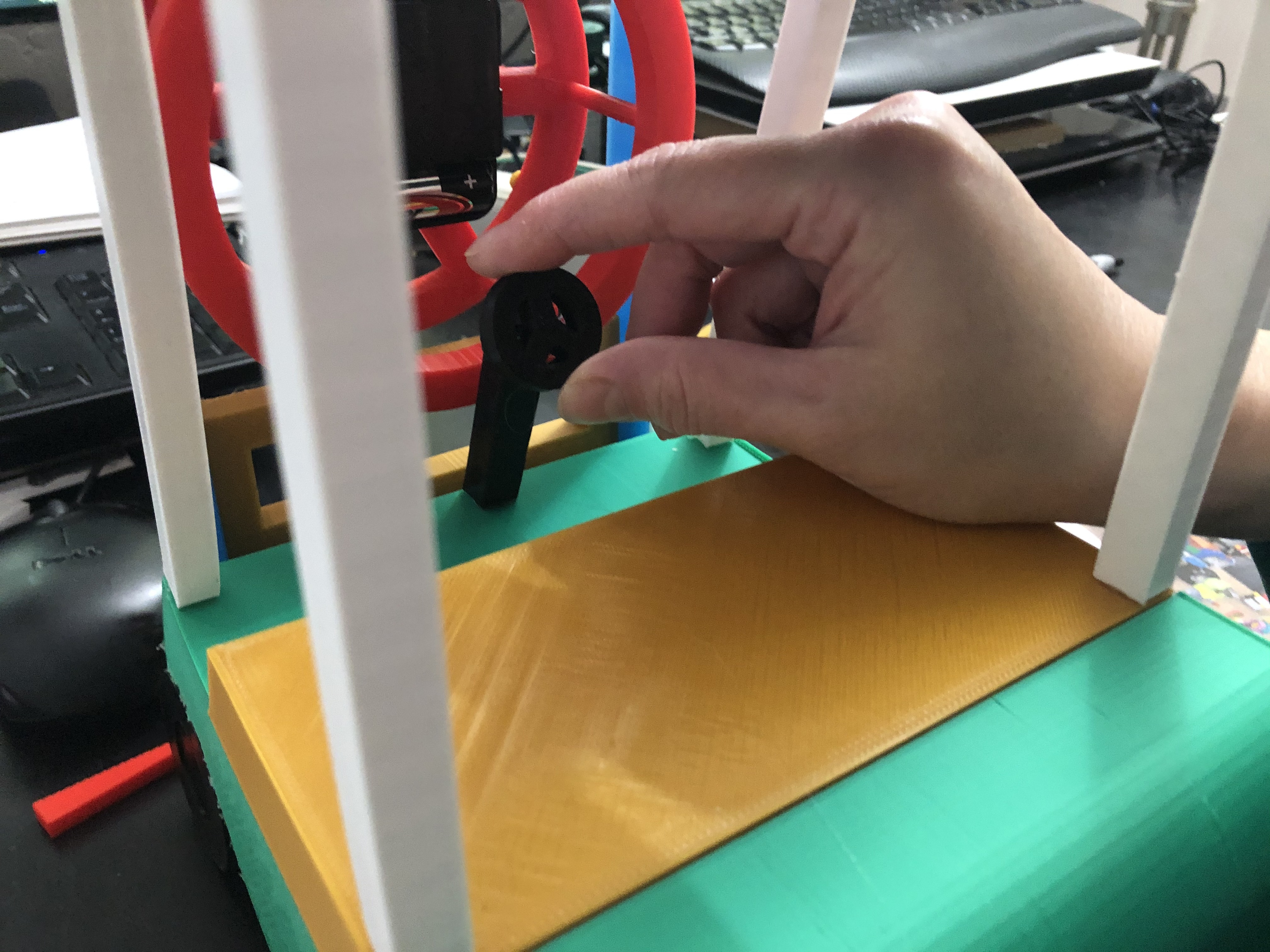
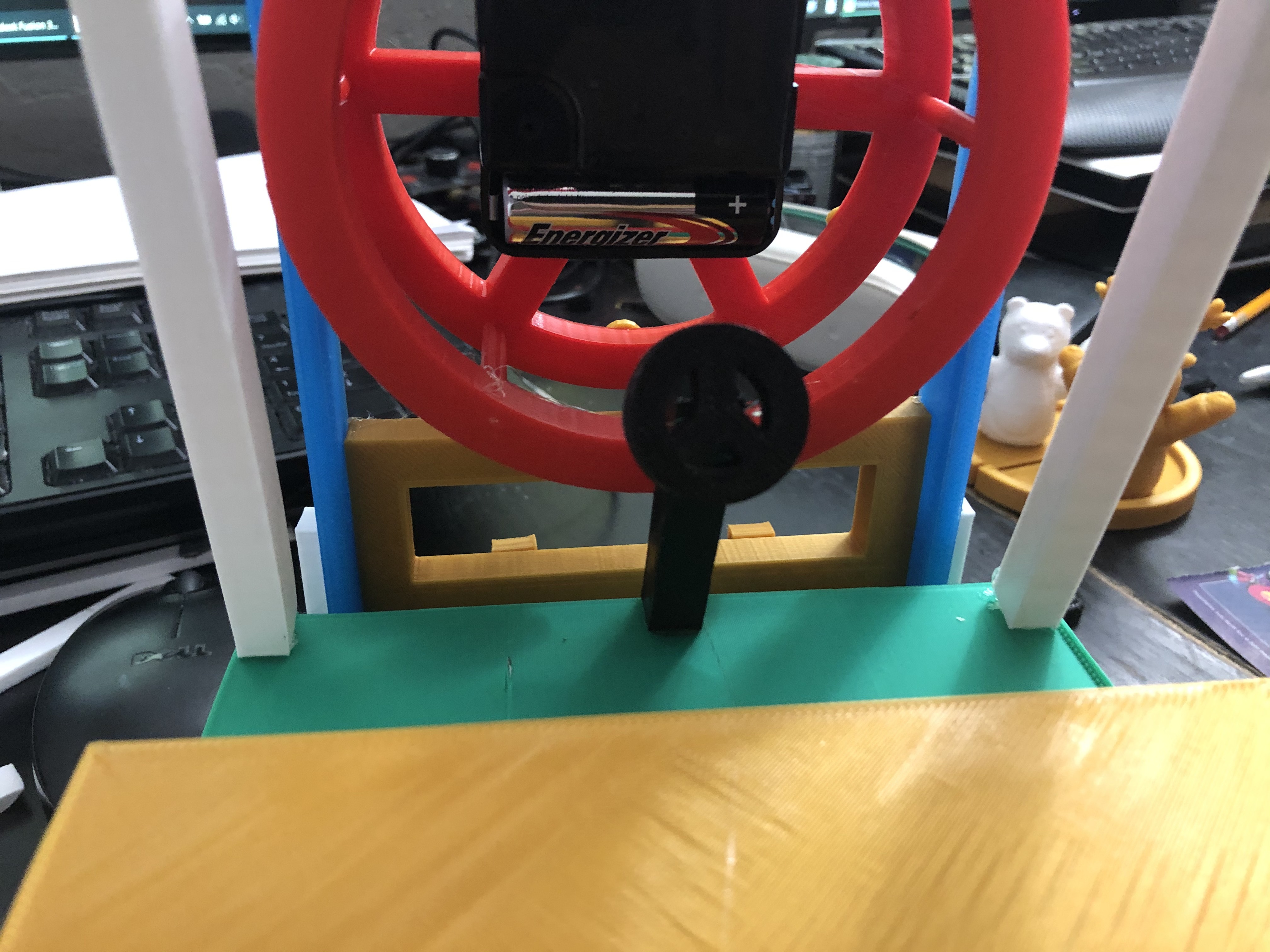
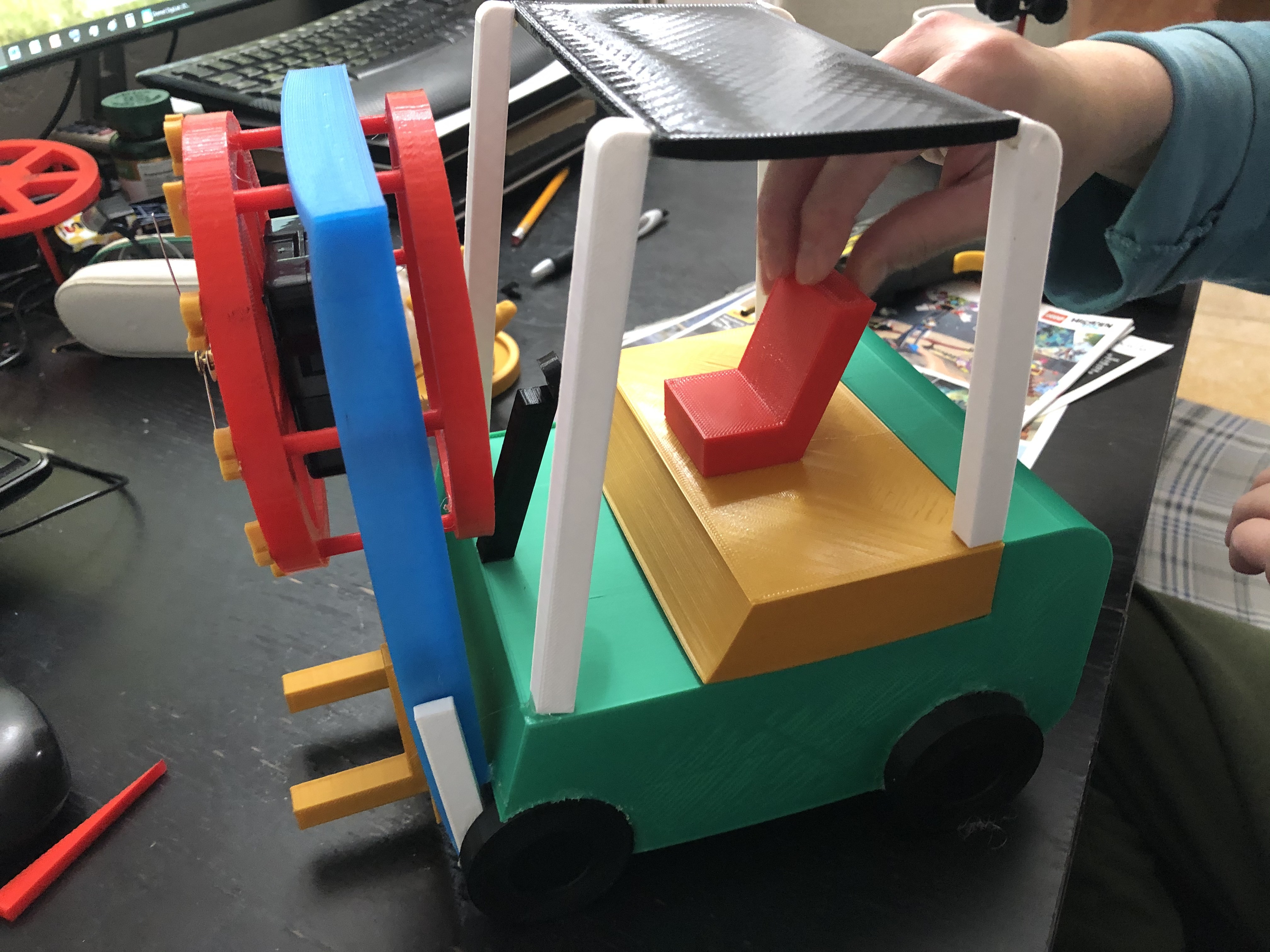
Finish the forklift body. Attach the seat and steering wheel.
Final Result
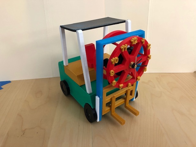
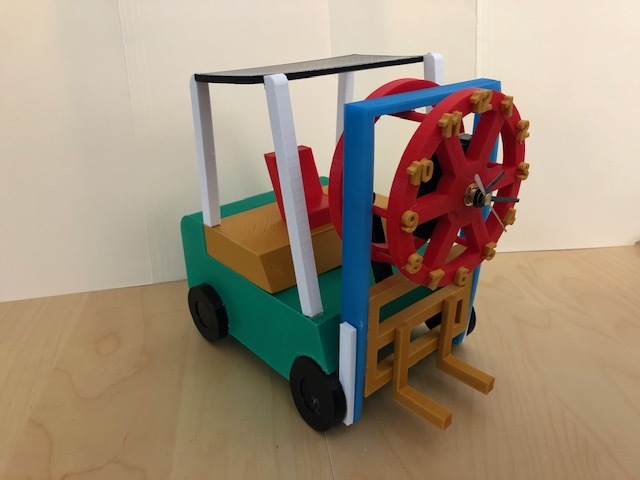
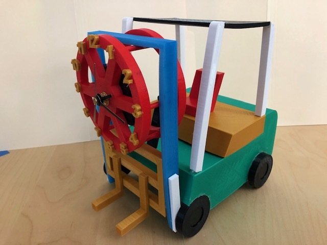
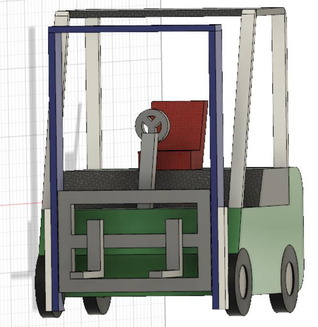
You already finished in making and assembling portable forklift clocks, only this clock cannot move, yet you can enjoy it. Frankly, it is my first experience designing in Fusion 360. Yet, I experienced some mistake when printing, such as errors in measurement and extrusion. Therefore, I did some modifications to obtain the perfect result. It has been a pleasure and fun time in using the design software. I hope that you enjoy my Instructable and like it. Thank you for reading this.