Follow Me - Raspberry Pi Smart Drone Guide
by Kroum in Circuits > Raspberry Pi
8706 Views, 25 Favorites, 0 Comments
Follow Me - Raspberry Pi Smart Drone Guide
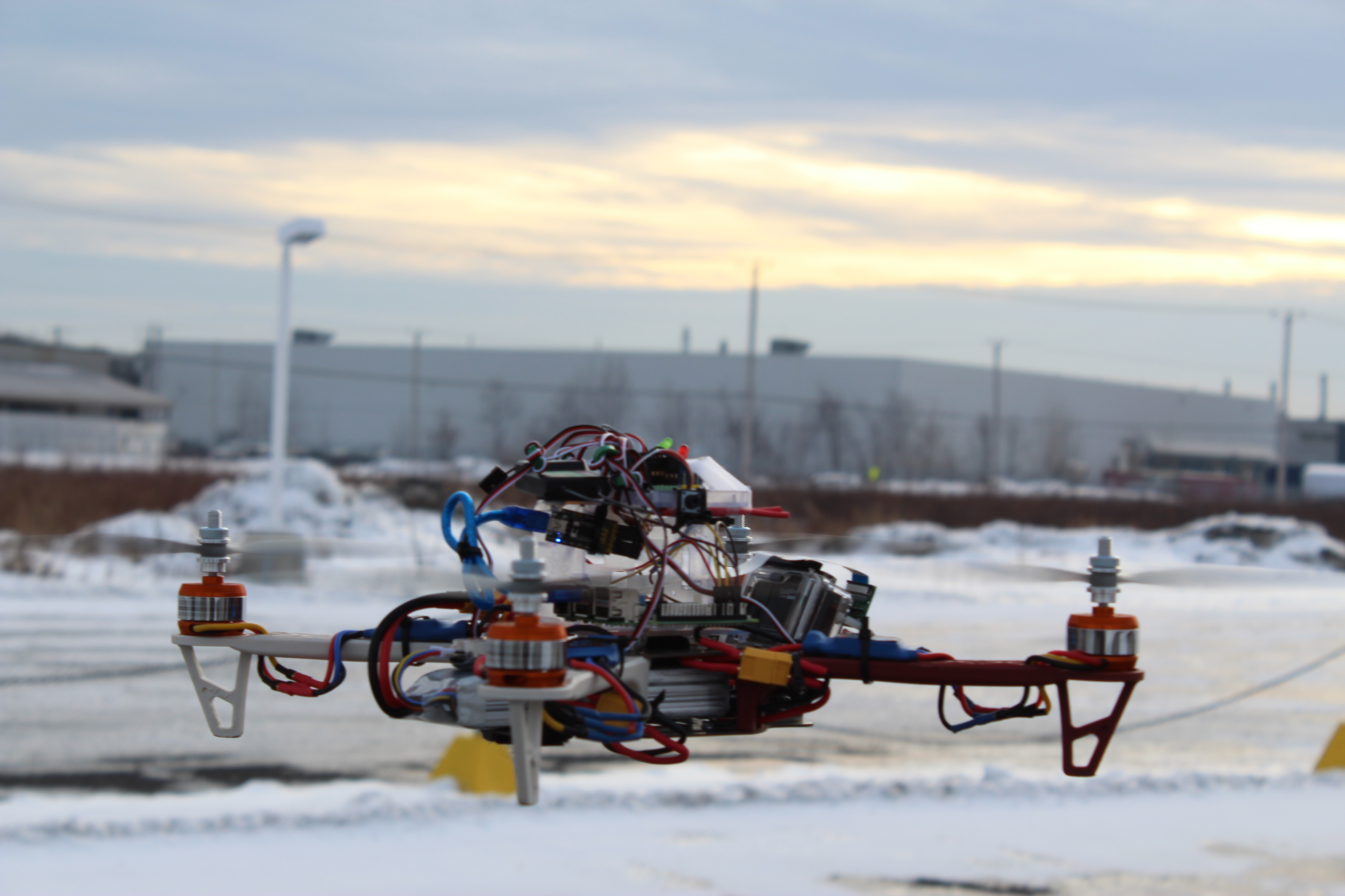
Have you always wonder how to make a drone from A-Z?
This tutorial shows you how to do a 450mm quadcopter step-by-step from buying the parts to testing your aerial robot on his first flight.
Additionally, with a Raspberry Pi and a PiCamera you can stream a live video on your device and control your drone in first person view! The Raspberry Pi also offers the possibility to improve your drone even more and add features as person tracking, obstacle avoidance and a weather station. This tutorial will show you how to make your drone follow you.
The advantage of the Raspberry Pi is mainly that it can process some artificial vision algorithms for features that require the drone to be ''smart''.
In this instructable, you will learn:
- What tools/parts you need to buy
- How to fix all the parts on the frame
- How to make the connections for the propulsion system
- How to configure your micro-controller
- How to connect the receiver to the transmitter
- How to stream a video taken by the drone on your phone
- How to tune your PID for a better control
- How to implement person tracking
Also the drone has a red LED that turns on when the drone is searching for someone and a green LED when someone is detected and the drone is following him. A button is also implemented to turn off the Pi before disconnecting the battery to the SD card of the Raspberry Pi doesn't get corrupted.
This tutorial aims to set the basics of how to build a customizable smart drone, so if you're a complete beginner, you've come to the right place!
Overview
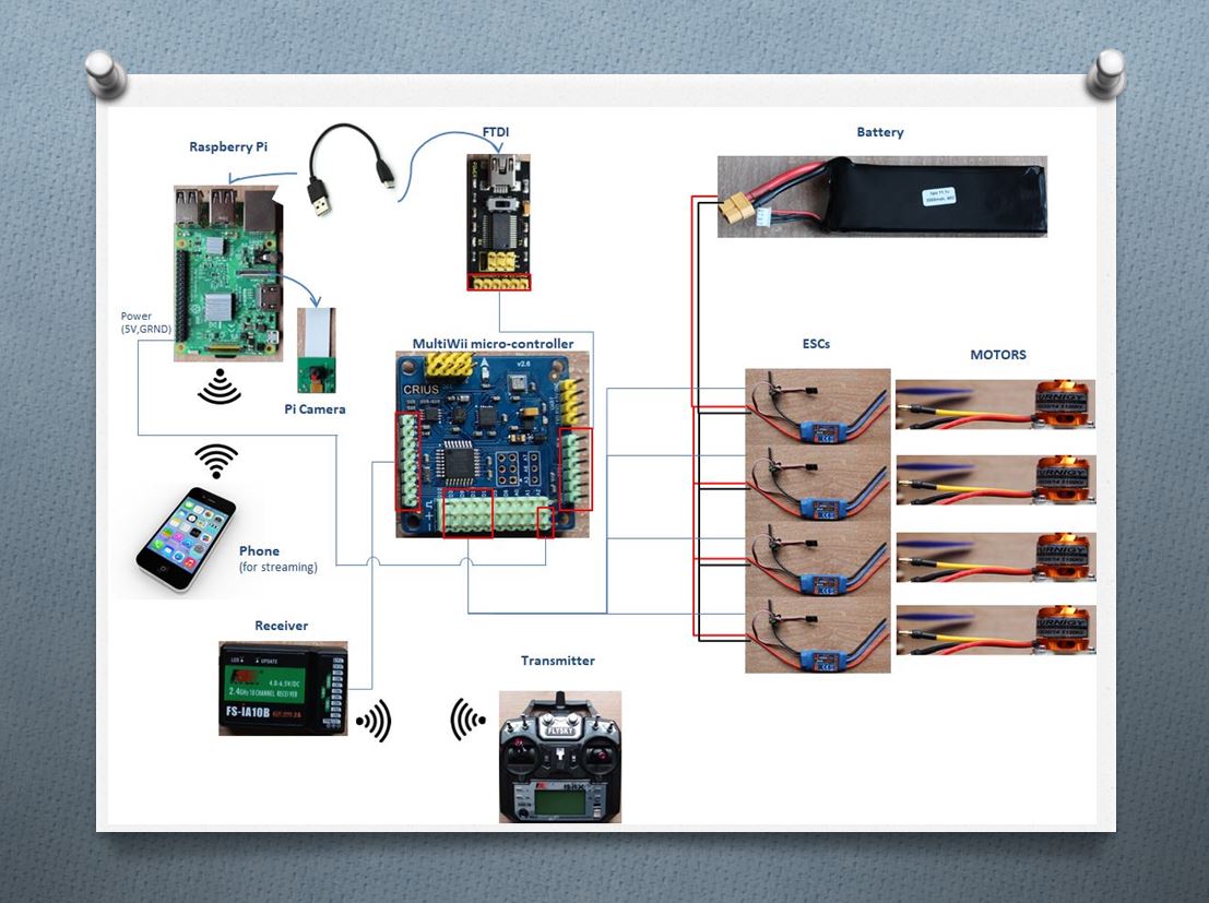
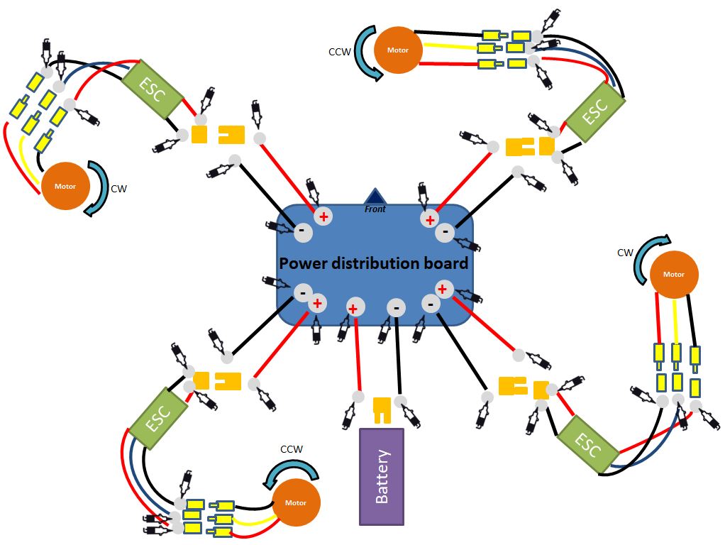
To build a quadcopter, we need 4 motors and 4 ESCs (Electronic Speed Controller) each one connected to a motor. A power distribution board is used to distribute the power from the battery to the 4 ESCs.
The ESC receives the command from the flight controller (here a MultiWii board) and transmits it to the motor.
This flight controller has a gyroscope, accelerometer and barometer. You can also add a bluetooth module and a GPS to it.
To do the connection between the Raspberry Pi and the flight controller, we use a FTDI adapter. Thus we can send commands to the controller from our Pi. Also, to do the PID calibration and to upload the firmware of the Mulltiwii on the flight controller, the FTDI will be very useful.
Finally, we control remotely the drone with a remote control that send commands to the receivers and sends them to the flight controller.
The Raspberry Pi also provides a stream that can be viewed on any browser from a device like a phone for example. This way we can view what the Pi Camera sees when it's in the air.
Gathering the Parts
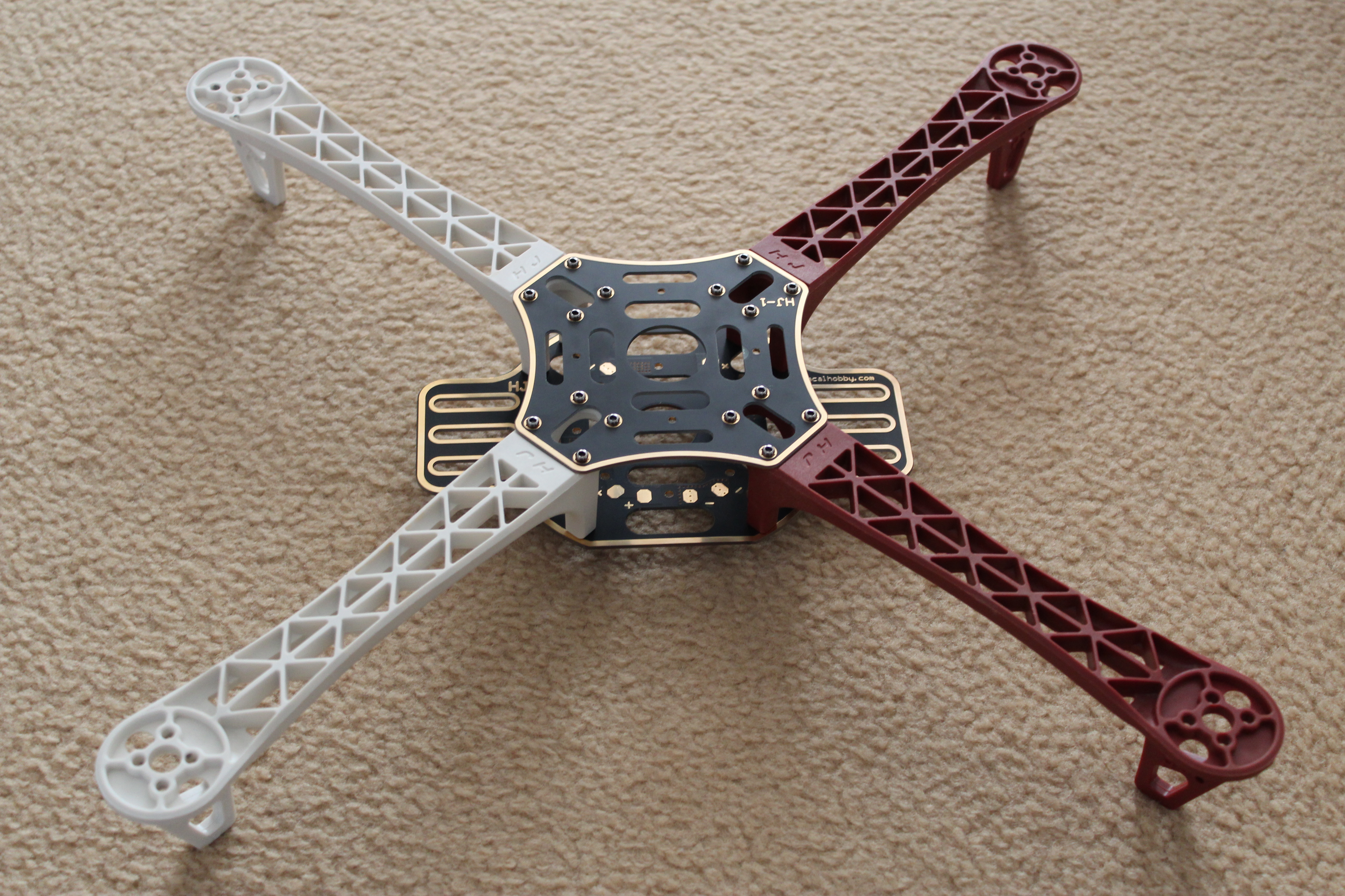
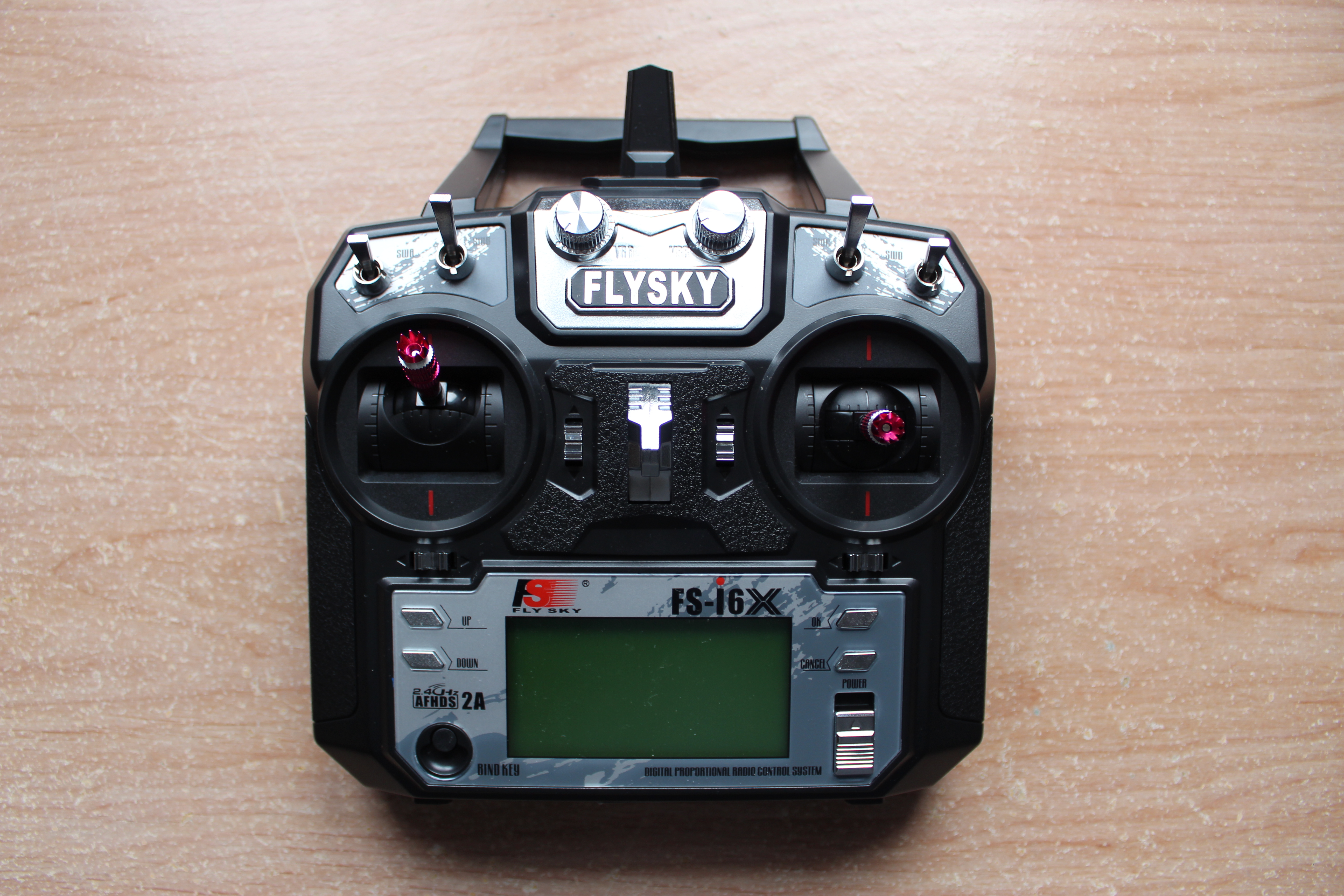
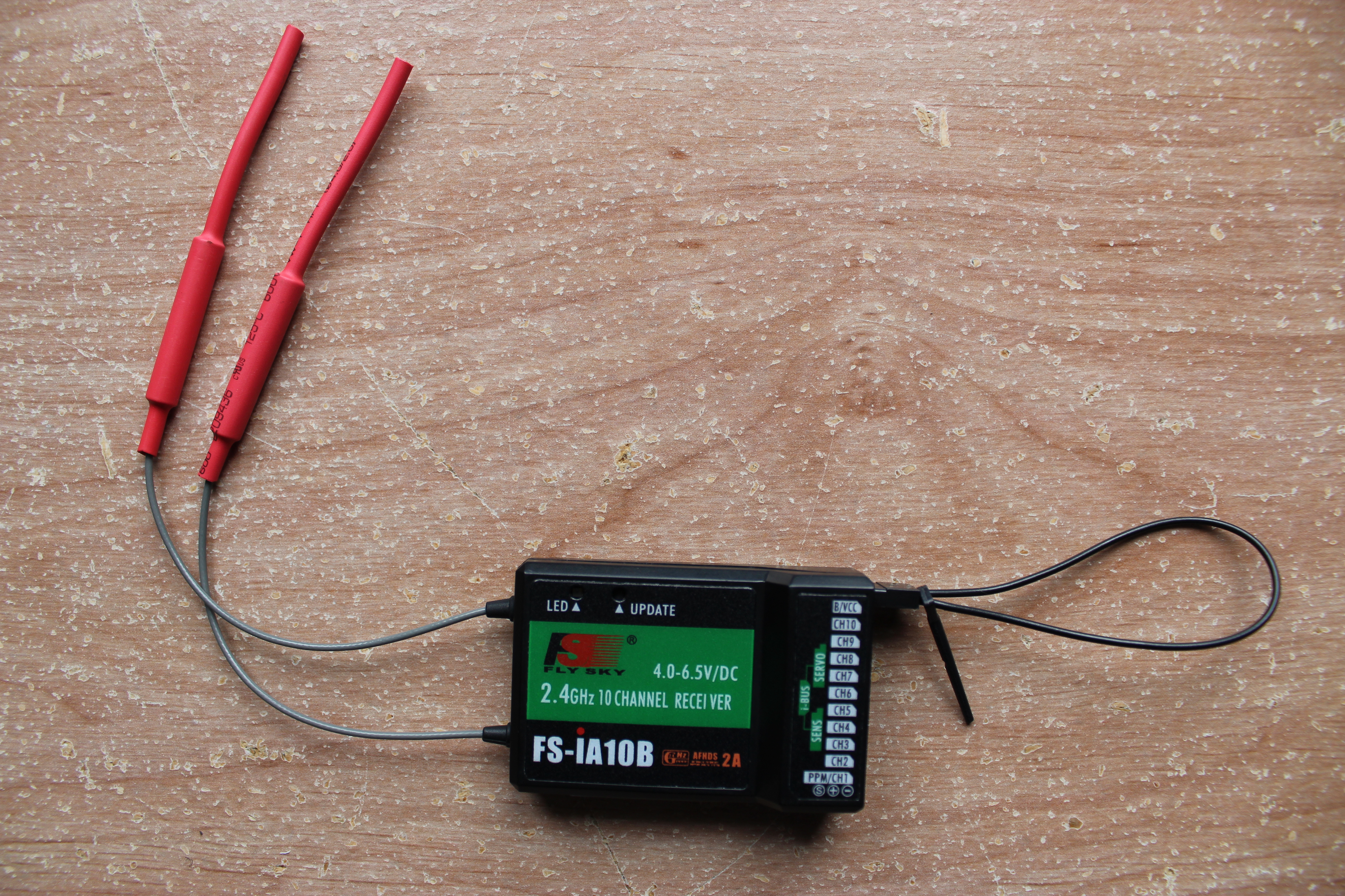
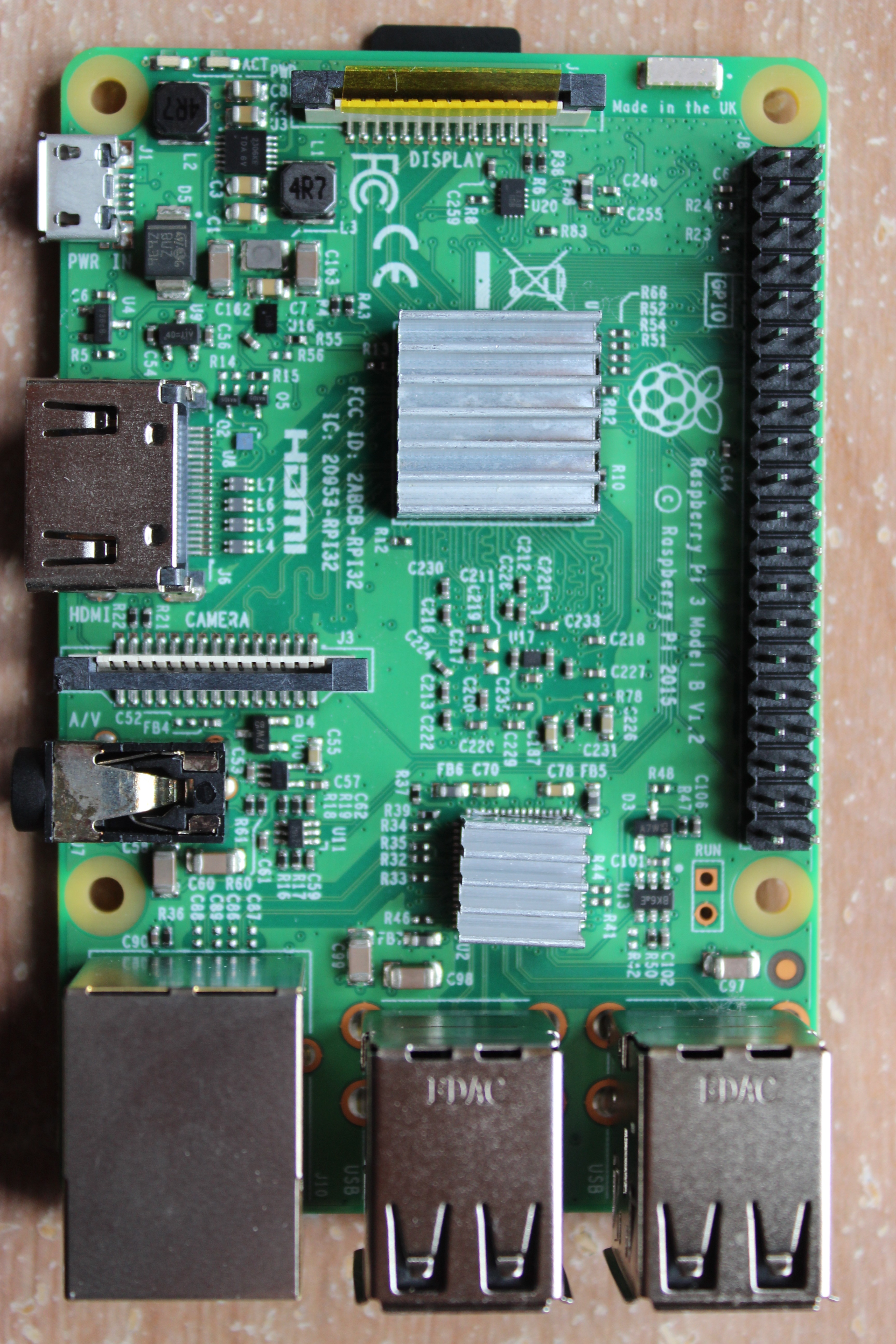
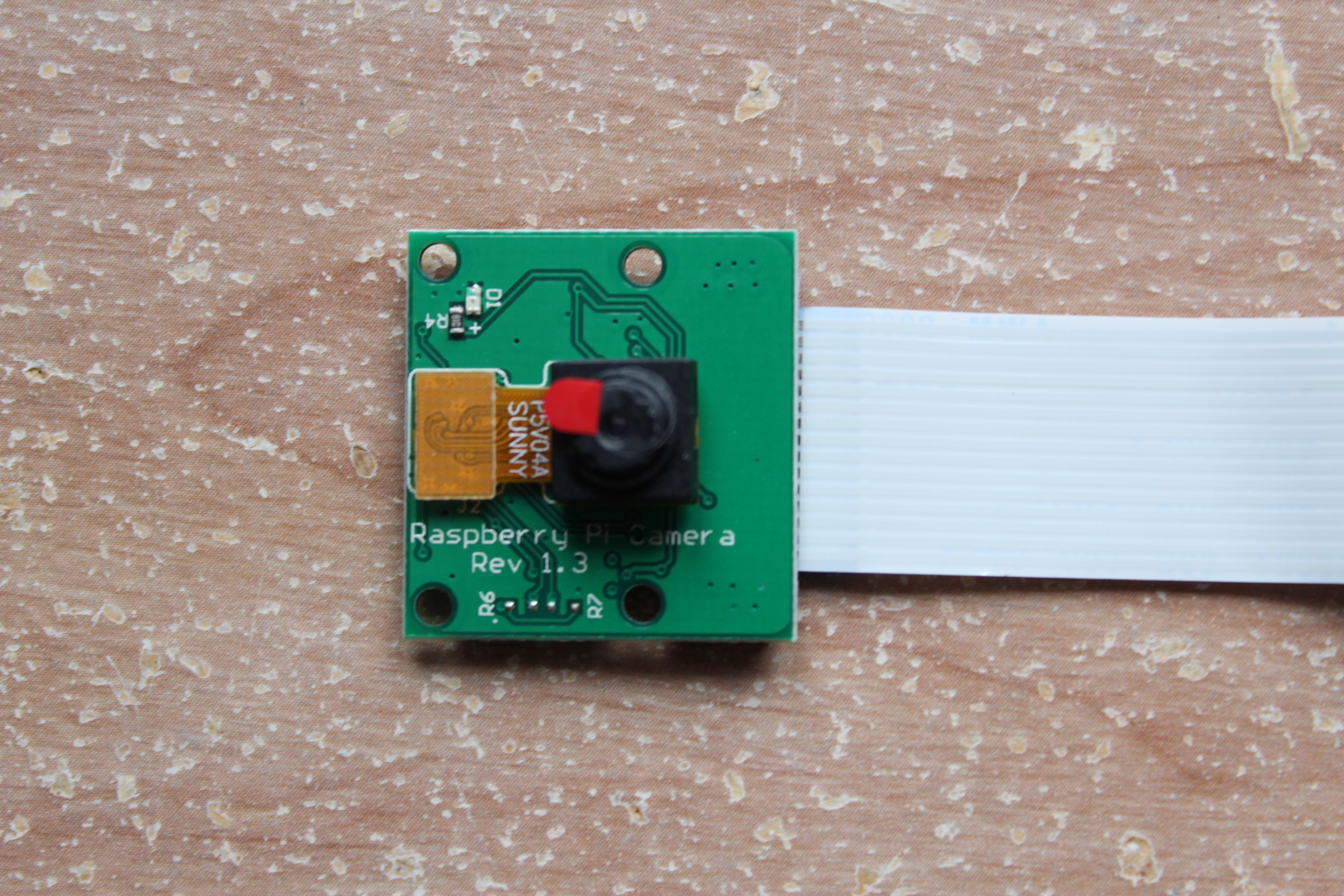
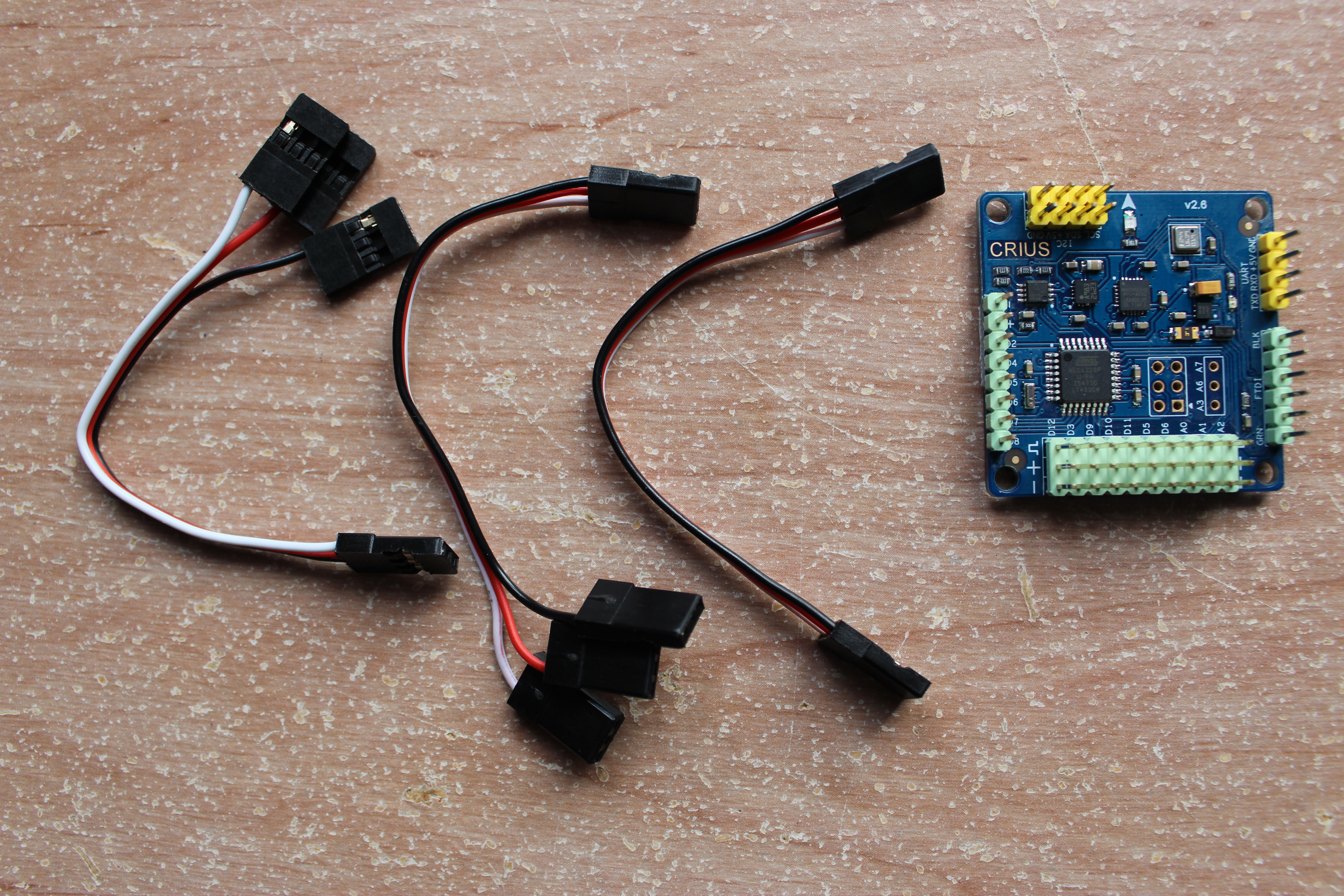
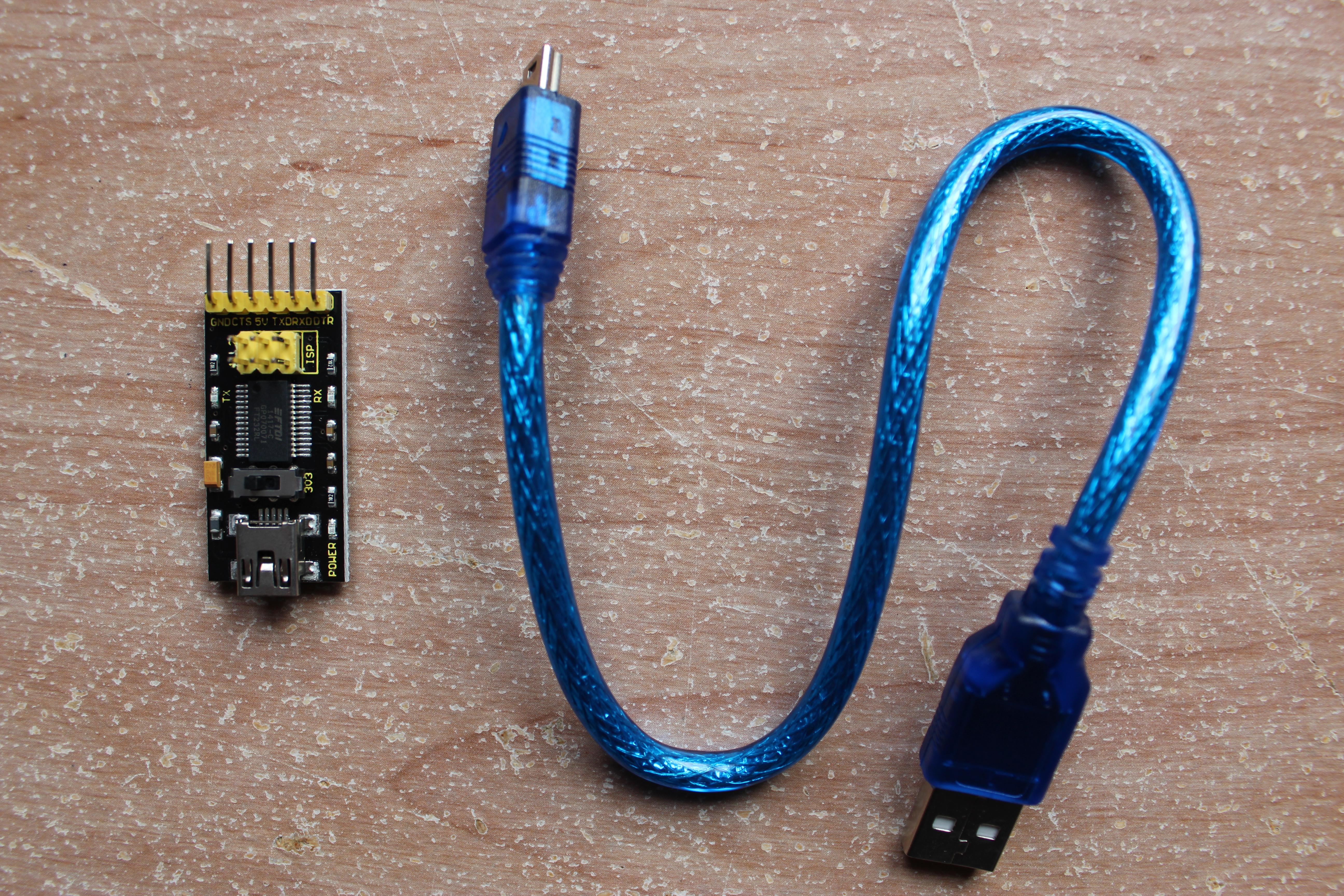
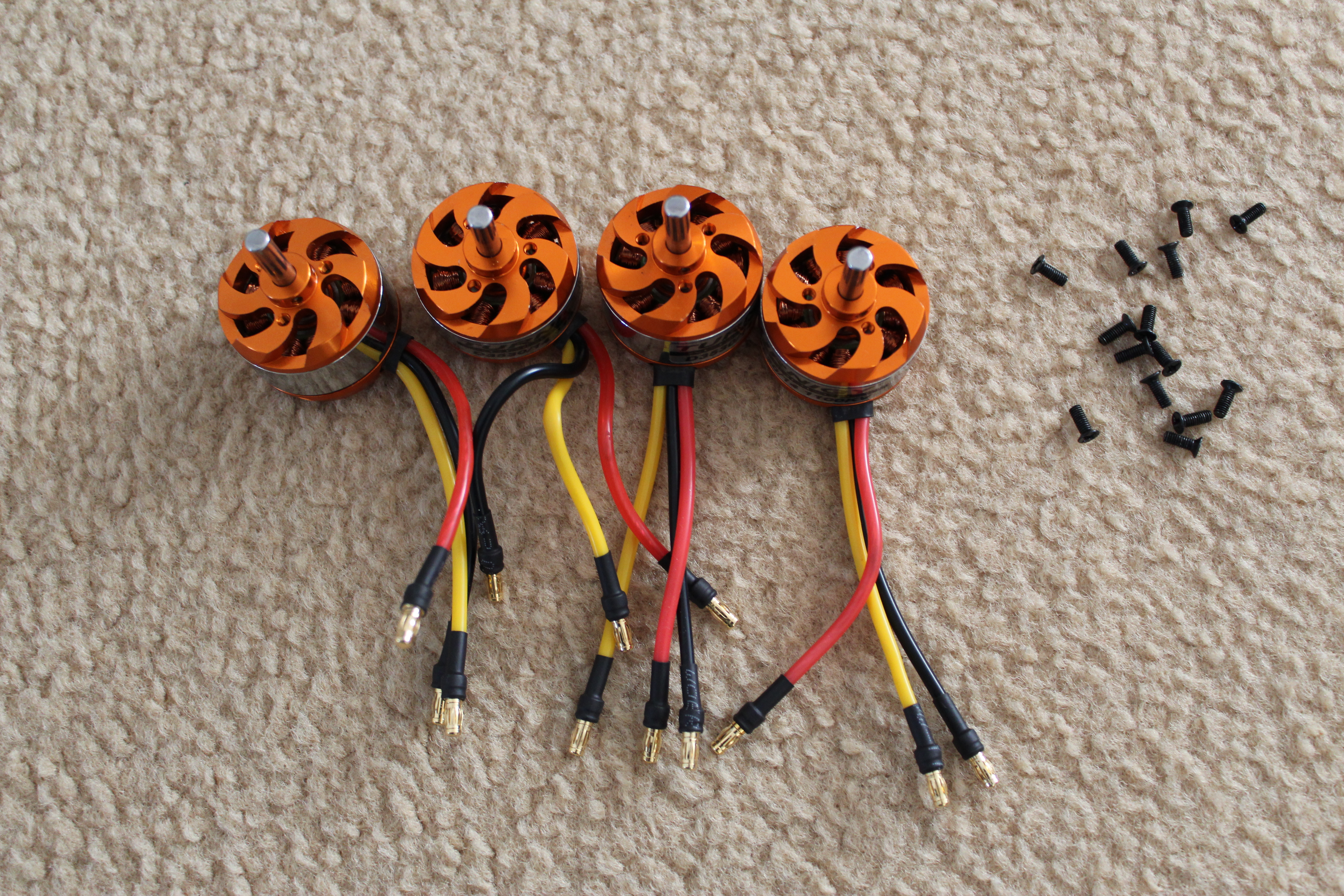
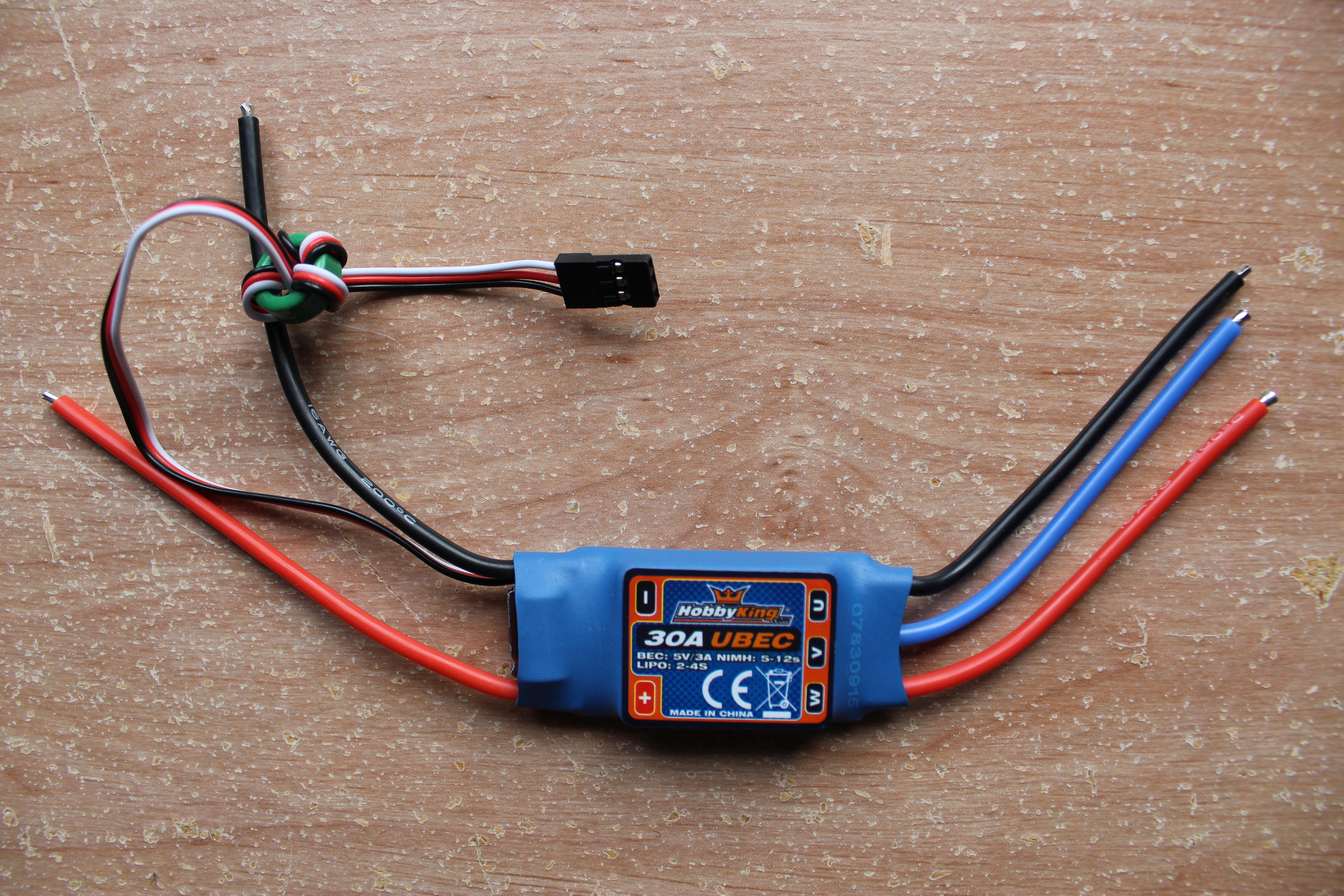

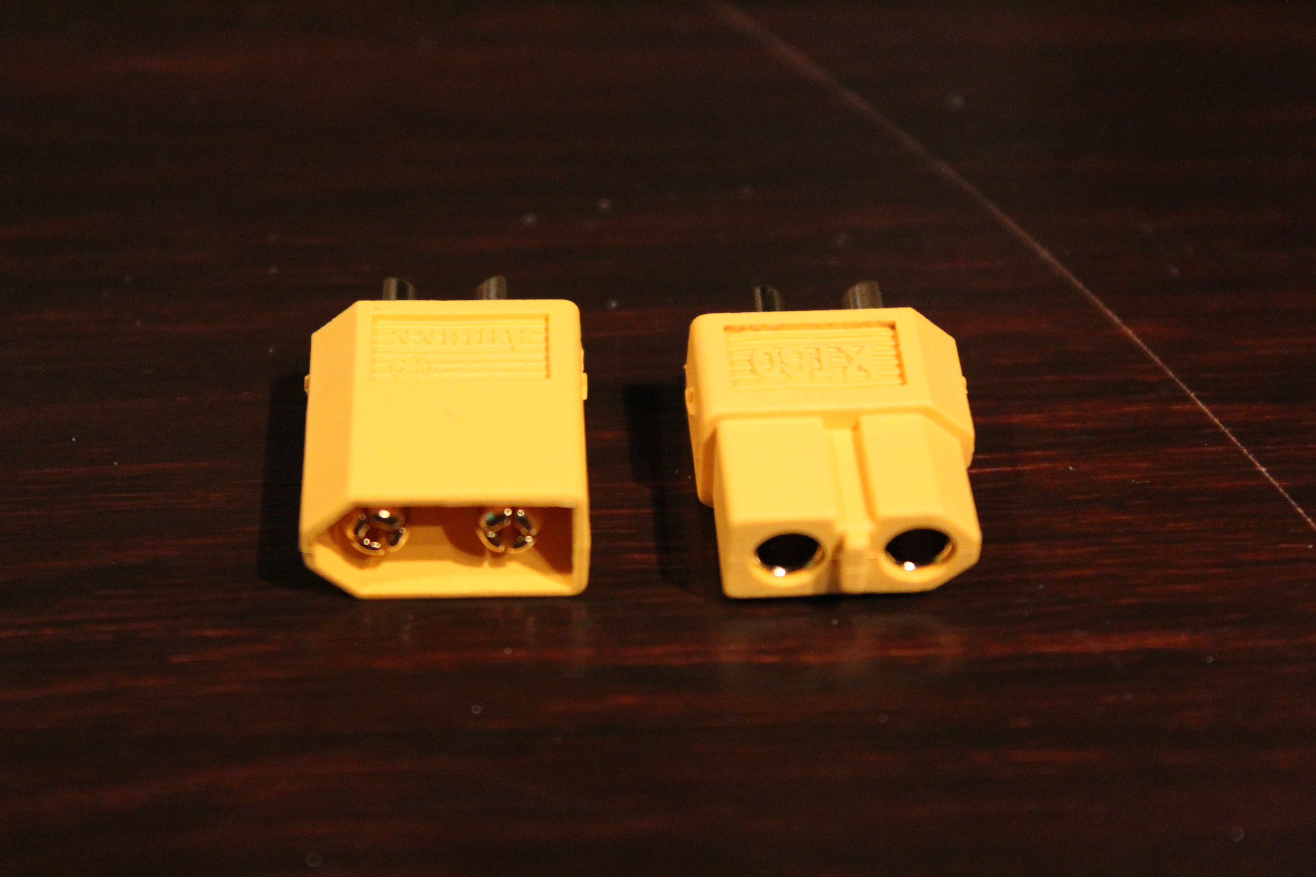

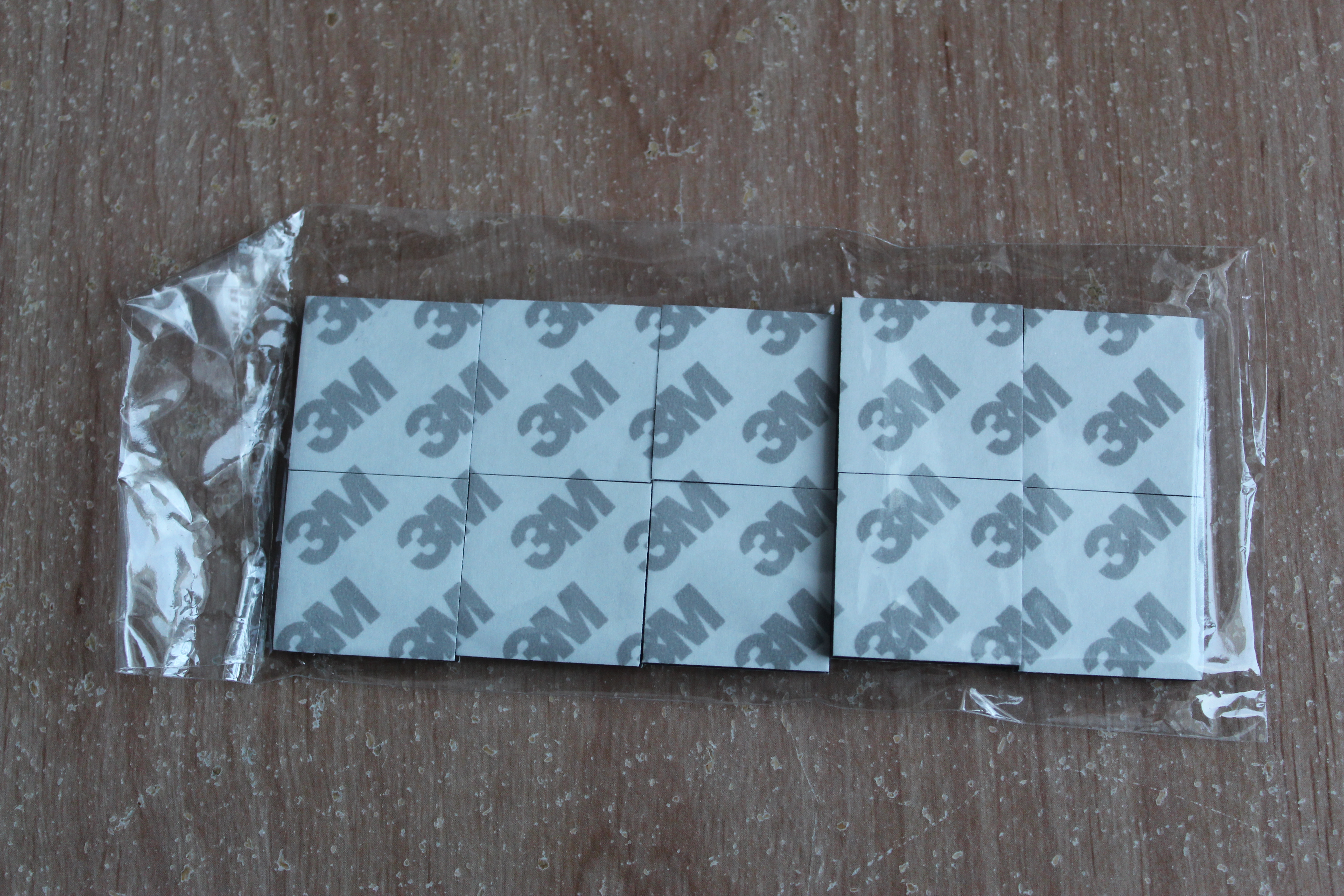
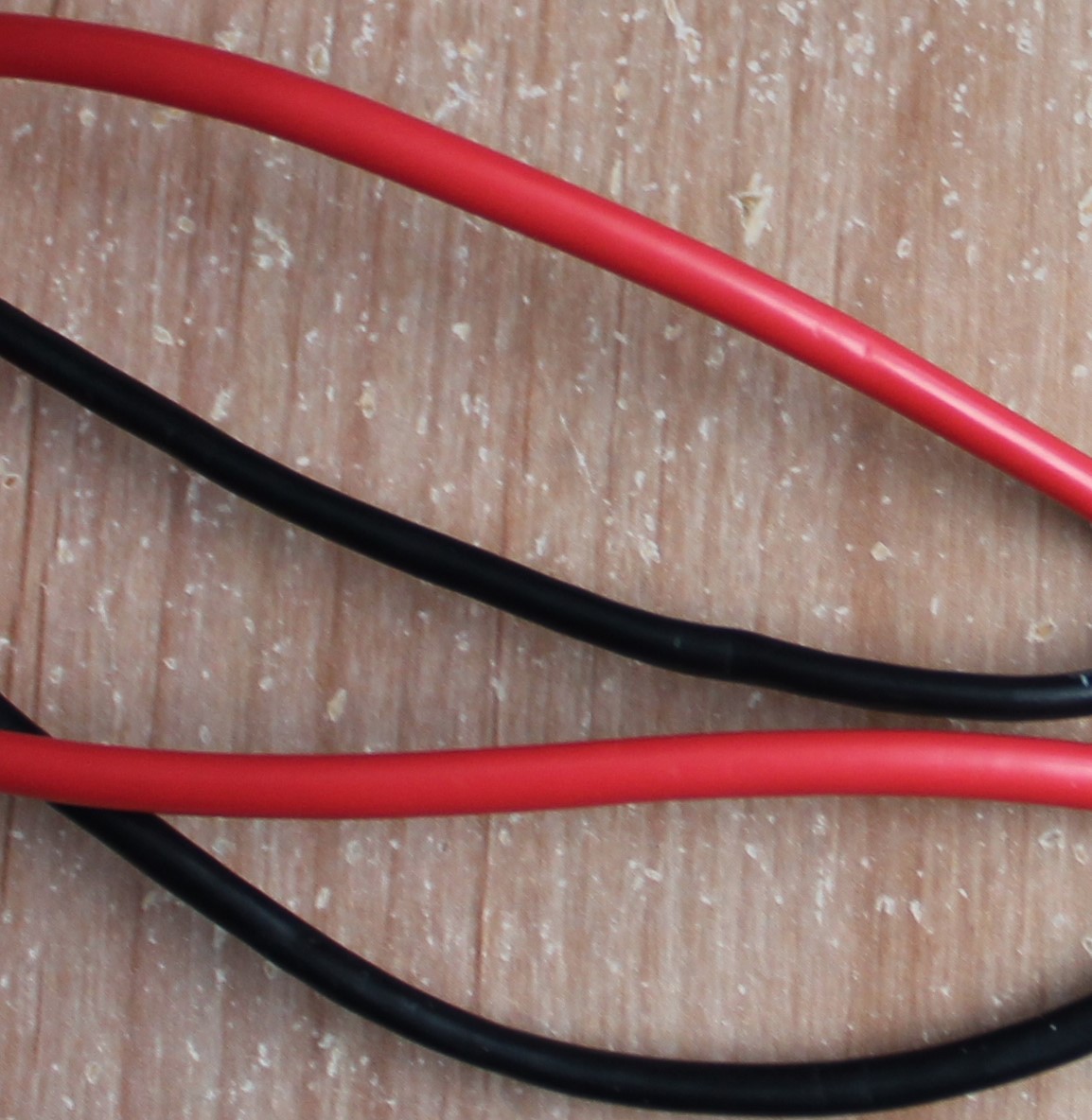
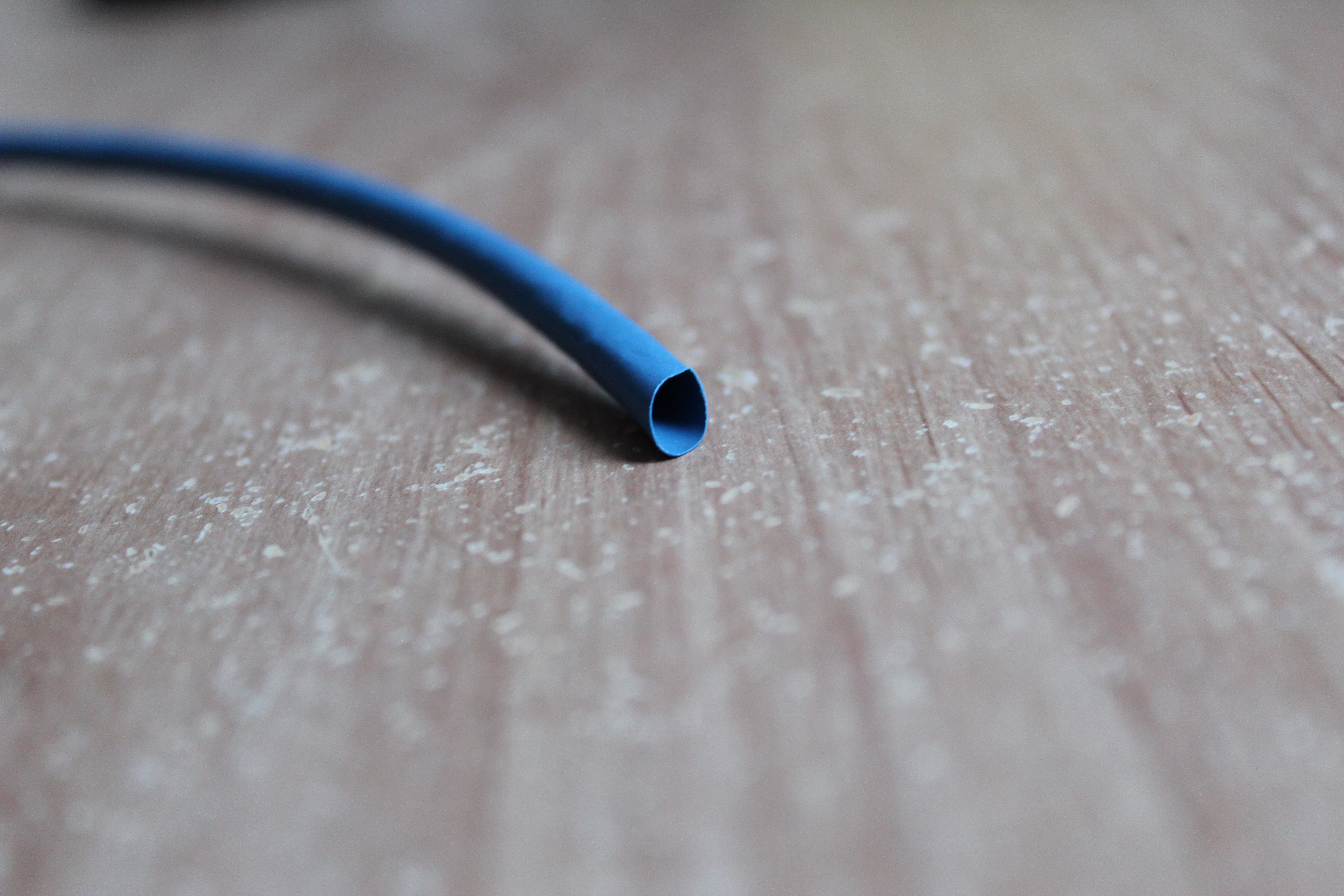
The following parts are required to successfully complete this tutorial:
1) The frame : 4-axis 450 F Frame
2) The transmitter and receiver : Flysky FS-i6X
3) The Raspberry Pi : Raspberry Pi 3 Model B Motherboard
4) The camera : PiCamera
5) The microcontroller : Crius MultiWii SEV2.6
6) The FTDI : FTDI USB to TTL /FT232 Converter
7) Small wires : Elegoo 120pcs Multicolored Dupont Wire
8) The motors (x4) : Liobaba 1100KV 2-4S Brushless Motor
9) The ESCs (x4) : Brushless ESC 30A Brushless ESC firmware w / 5V 3A UBEC
10) The battery : HRB 11.1V 5000mAh 3S 50C-100C LiPo Battery
11) The connectors : Gold Platted connectors 3.5mm (x4) and Artrinck XT-60 60A/100A Male Female
12) The propellers (x3) : FidgetGear 10x4.5 Propeller (Blue)
13) The flight controller mounting pad : Flight Controller Mounting Pad
14) Some heats-shrinkable sheaths : Shrinkable tube - SODIAL
15) Wires : 16GA wire
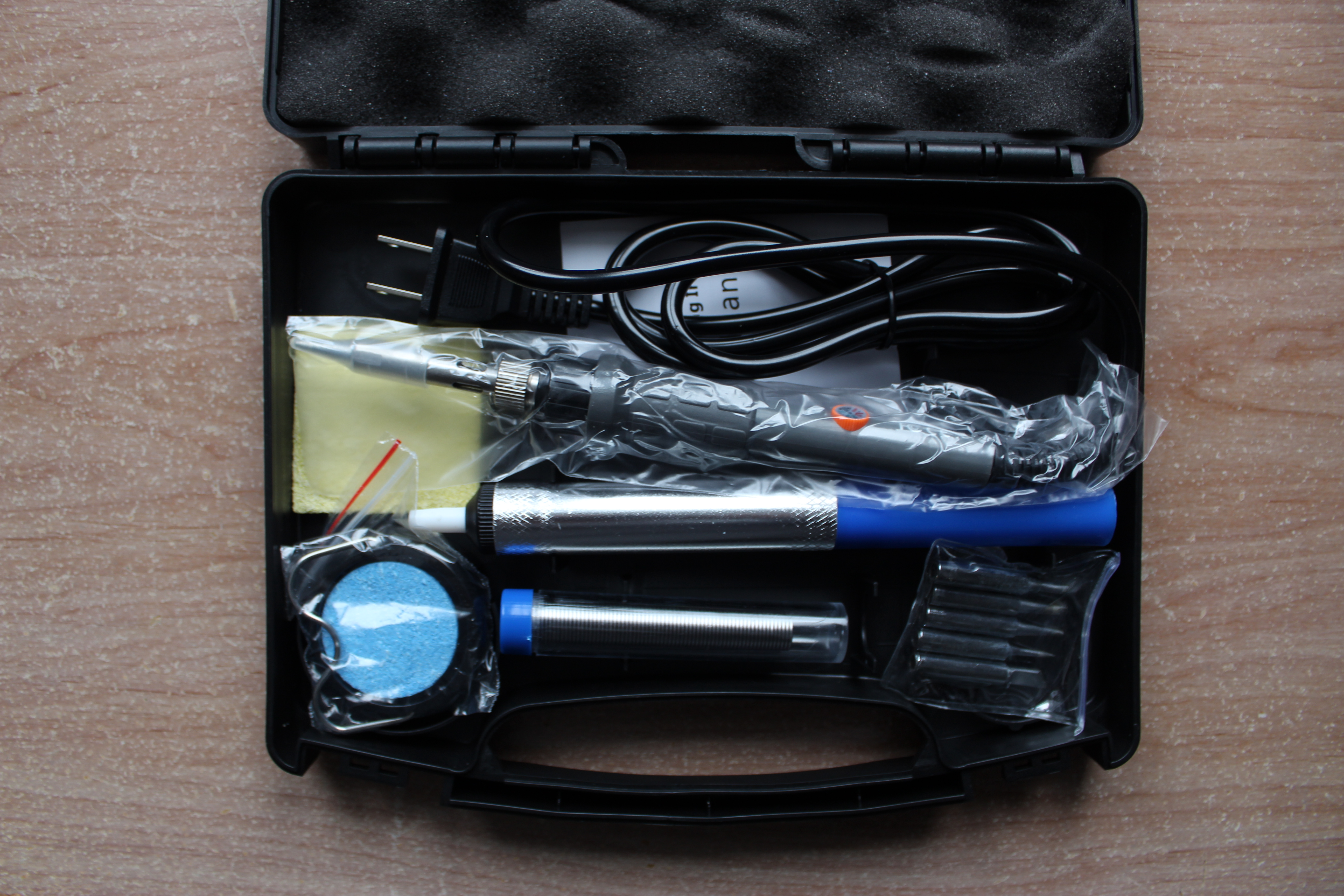
16) The soldering iron : Holife Soldering Iron Kit, 60W 110V Adjustable Temperature Controlled Welding Tool
Optional
- A buzzer : Venom Low Voltage Monitor for 2S to 8S LiPO Batteries
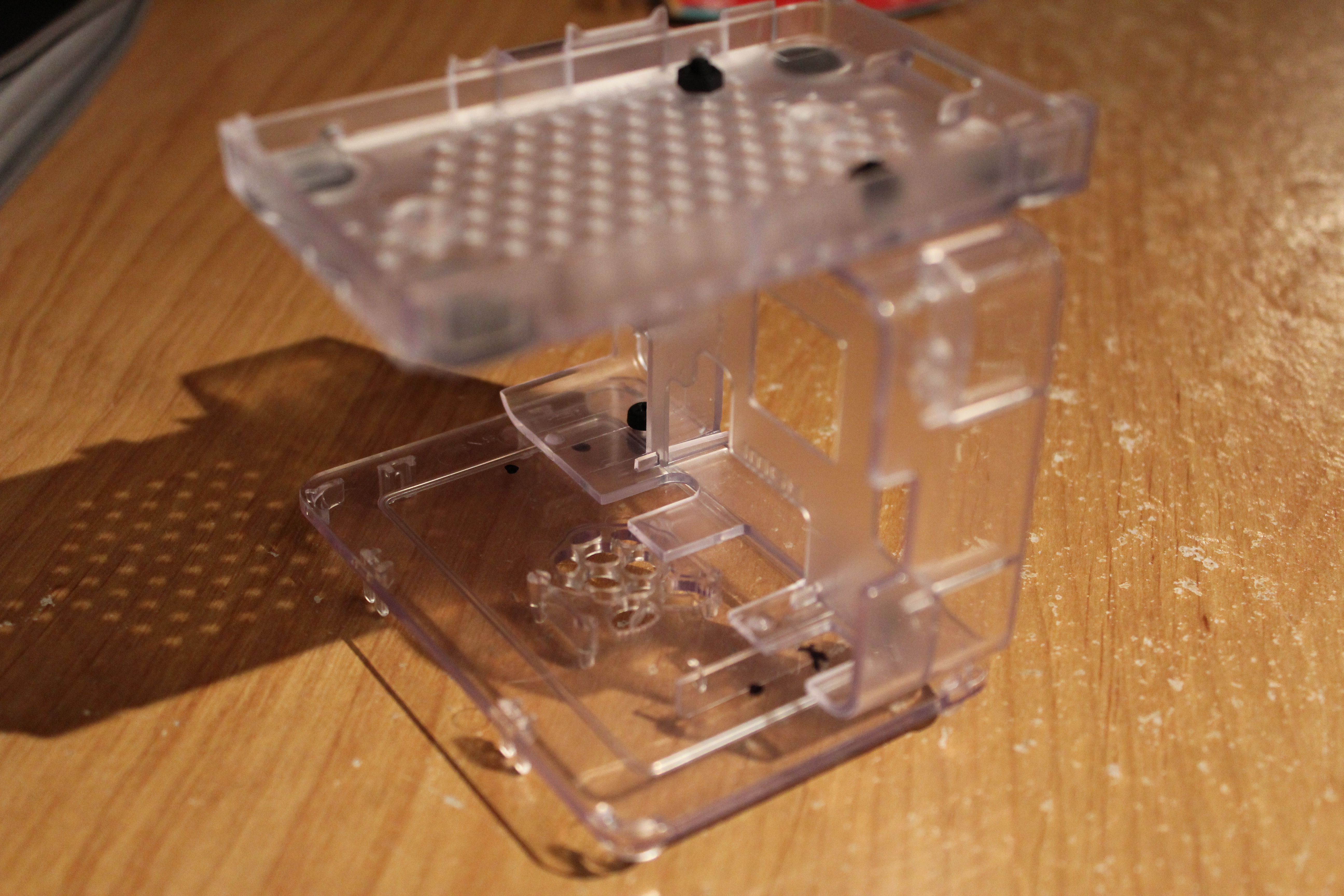
- A support/rack for the Pi and flight controller : Box Storage Case for Raspberry Pi
- Improve your soldering experience with : Elenco Helping Hands and 60-40 Tin Lead Rosin Core Solder
The TOTAL cost of all these parts should be 450.71 CAN$.
Soldering and Fixing Parts on the Frame
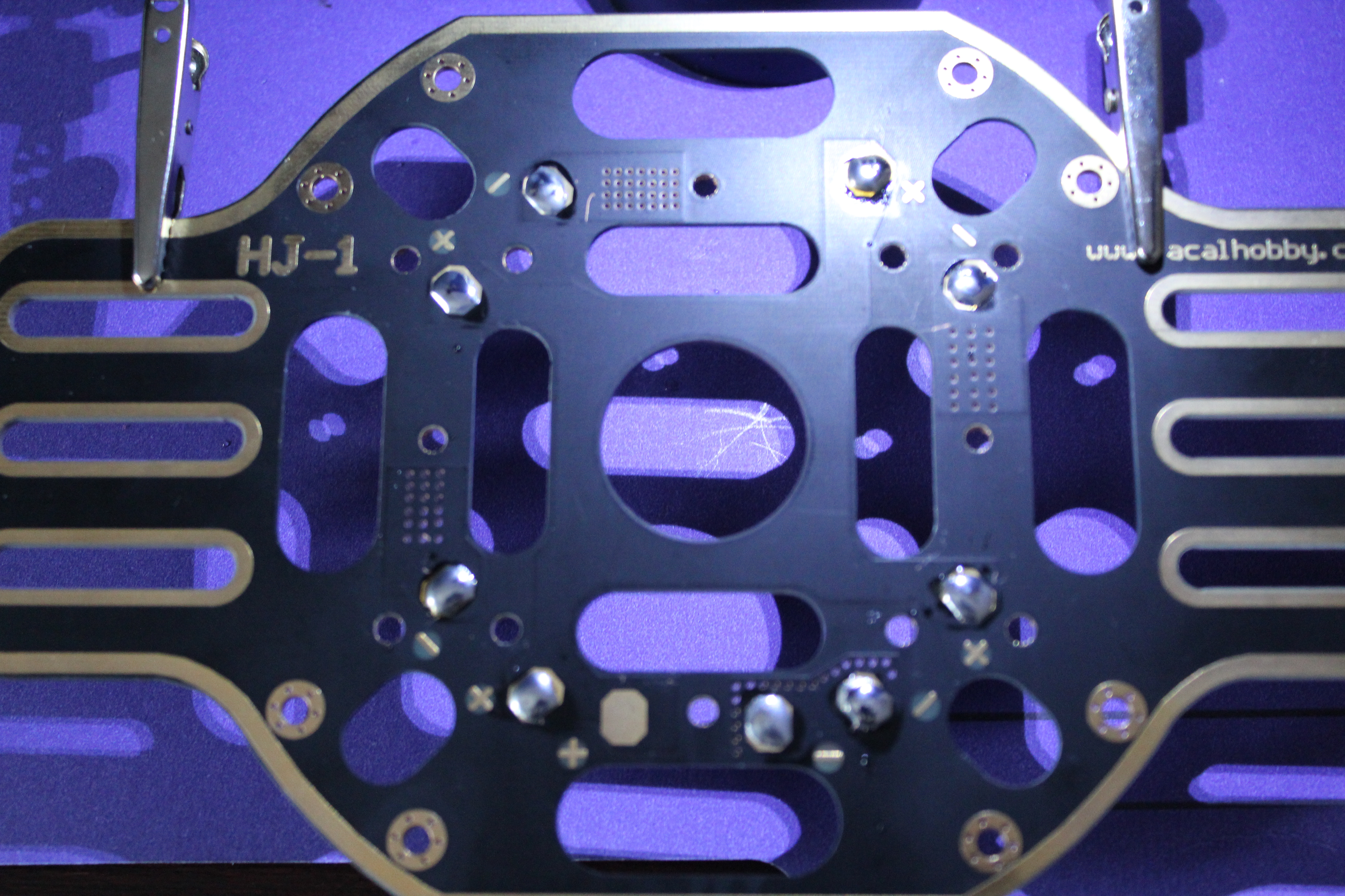
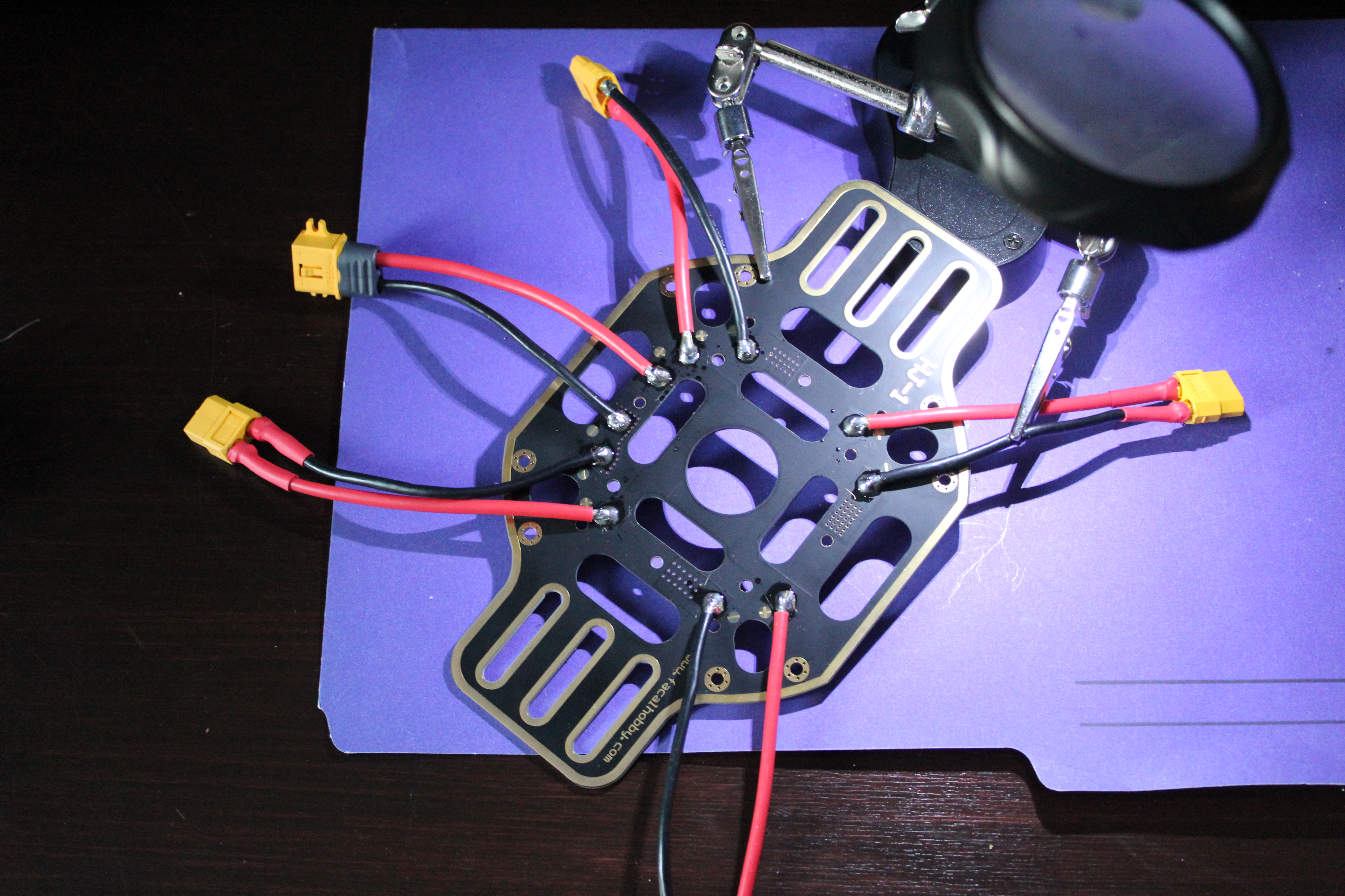
Two parts need soldering:
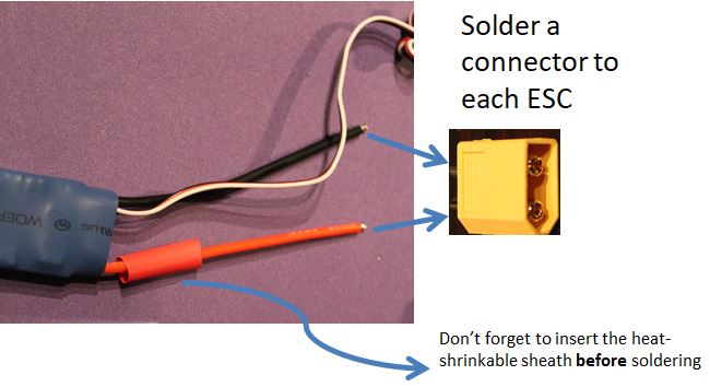
- The ESCs (they don't come with connectors at the extremities)
- The power distribution board (in our case integrated in the frame)
Use the female tx connectors on the wires you added to the distribution board, the male tx connectors on the ESCs' distribution board side wires and the gold 3.5mm connectors on the ESCs' motor side wires. Don't forget to add the heat-shrinkable sheath to insulate (we don't want to see any bare wire).
Advice for soldering:
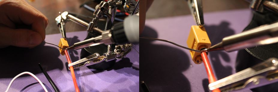
- Use the middle size flat iron tip (provided in your soldering kit) and heat up the solder iron to 400 degC.
- Clean often the tip of the soldering wire with the water sponge.
- Melt some soldering on the two surfaces you want to connect first, then stick them together and add more solder.
For more details about how to solder everything don't hesitate to have a look at our website.
Fix the parts on the frame:
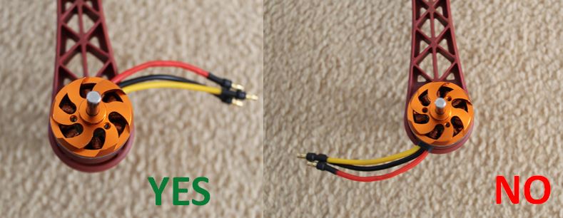
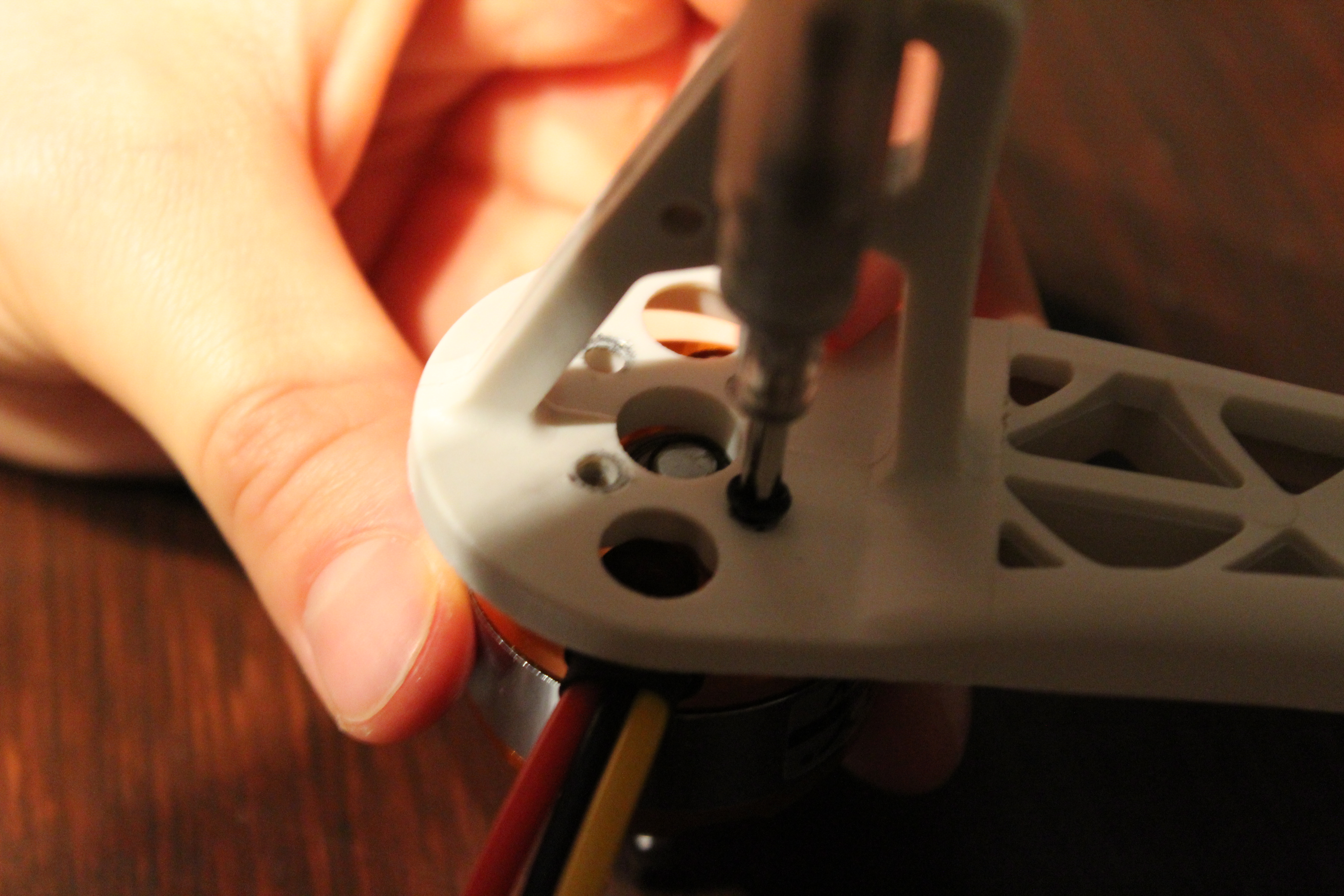
- Use two screws to fix the motors at each arm's extremity.
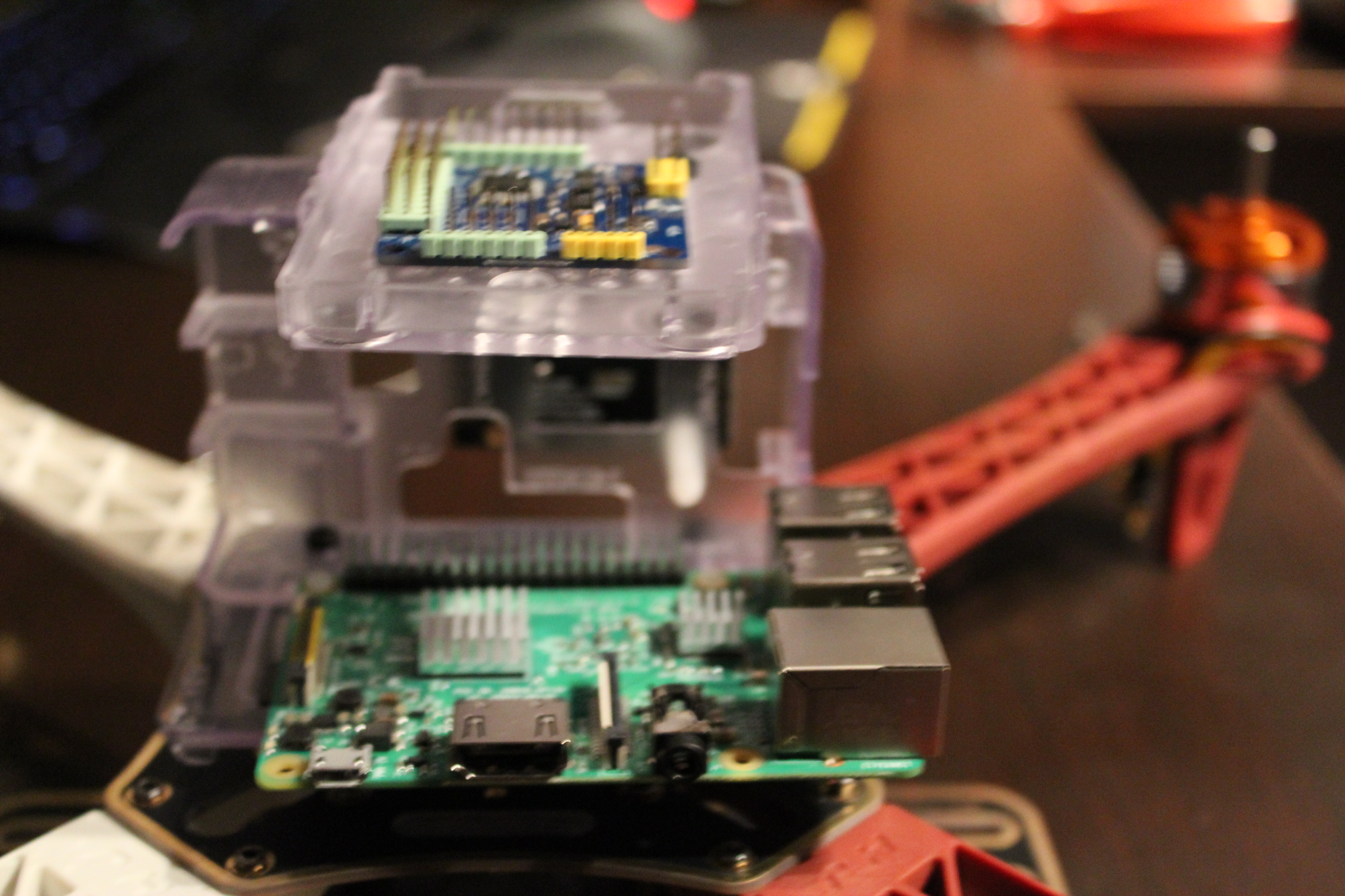
- Fix the electronics' support on the frame with nuts and bolts.
- Fix the Pi on the support with nuts and bolts.
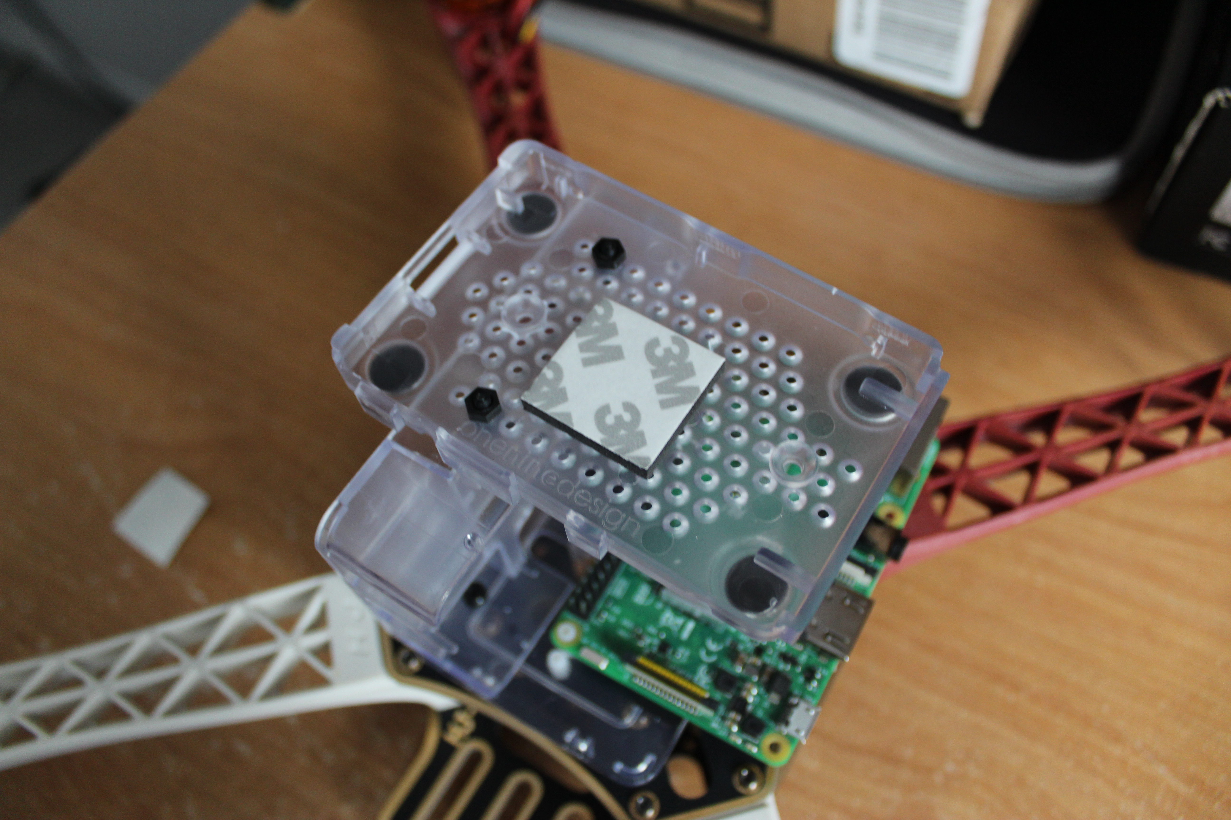
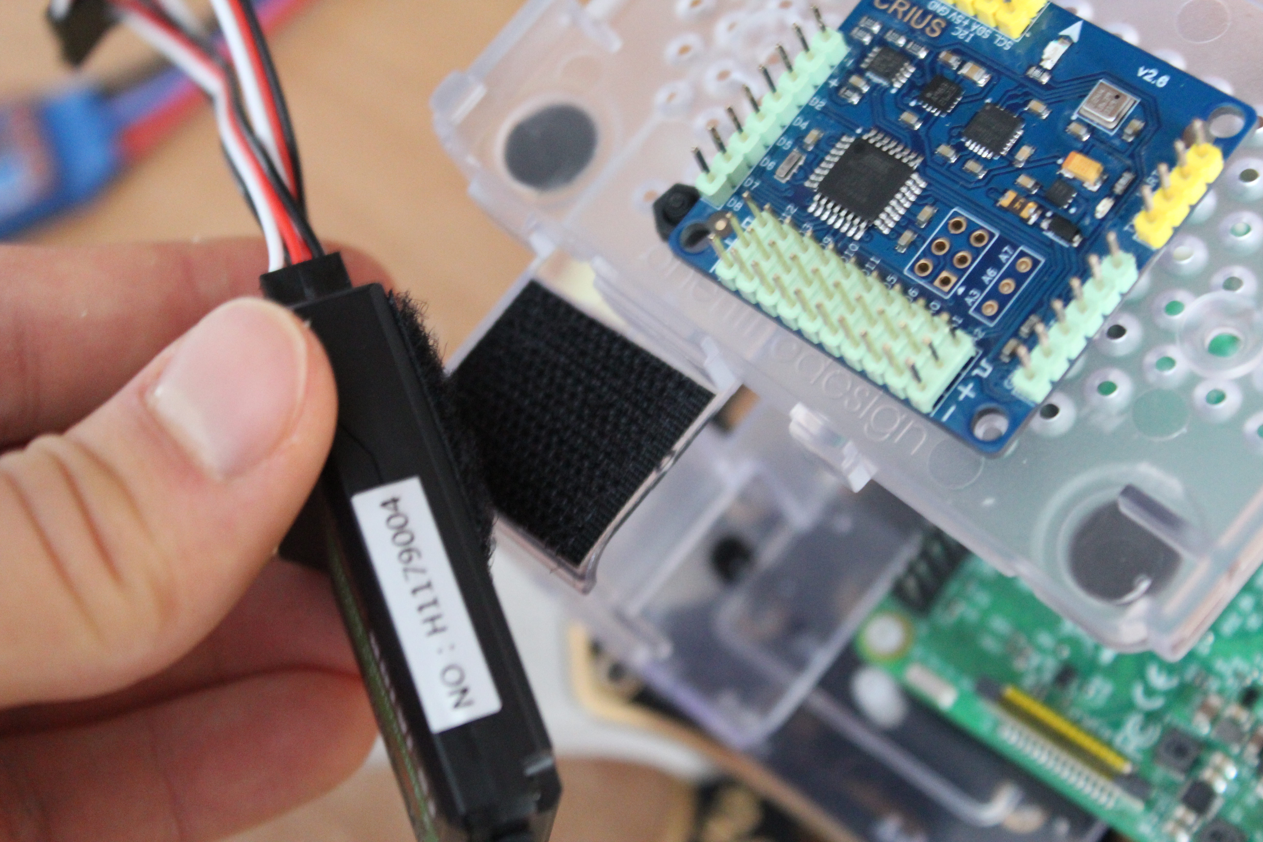
- Stick some mounting pad(to absorb vibrations) on the top of the support and stick you Multiwii to it making sure it's exactly in the middle of the frame and with the arrow pointing between two arms of the same color.
- Stick the receiver to the support with some velcro.
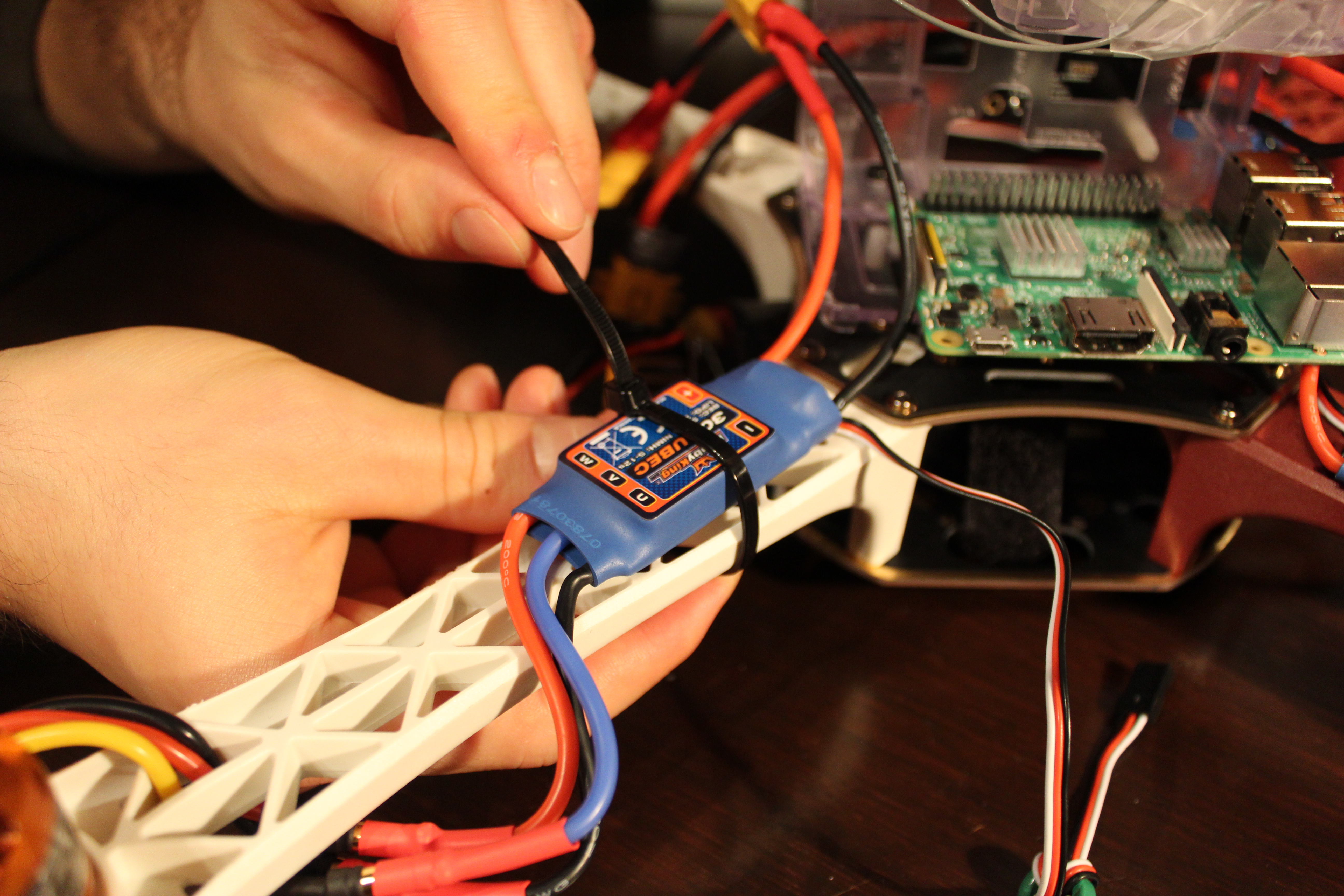
- Put you ESCs on each arm with tie-wrap.
- Use straps to attach the battery at the bottom level of the frame.
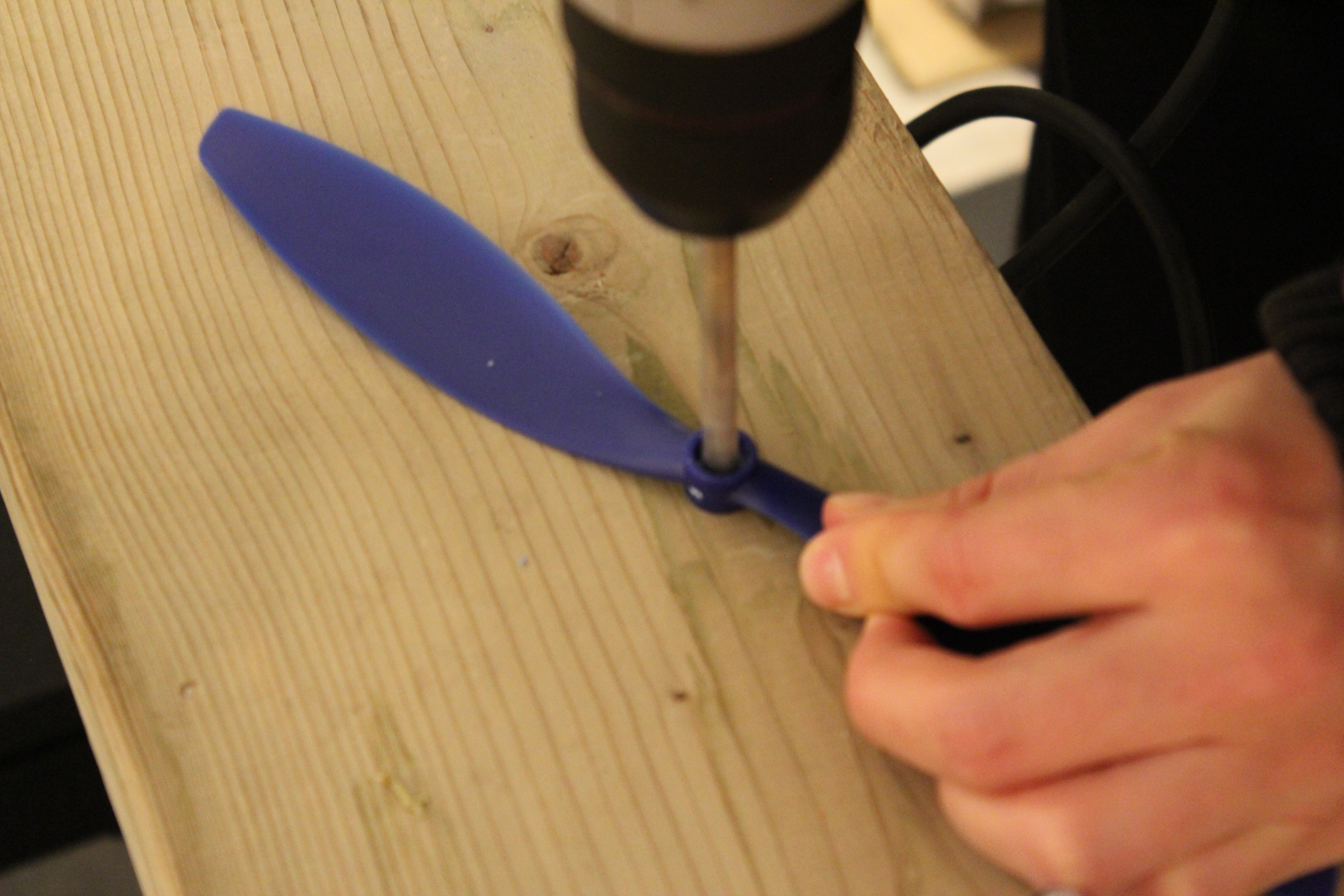
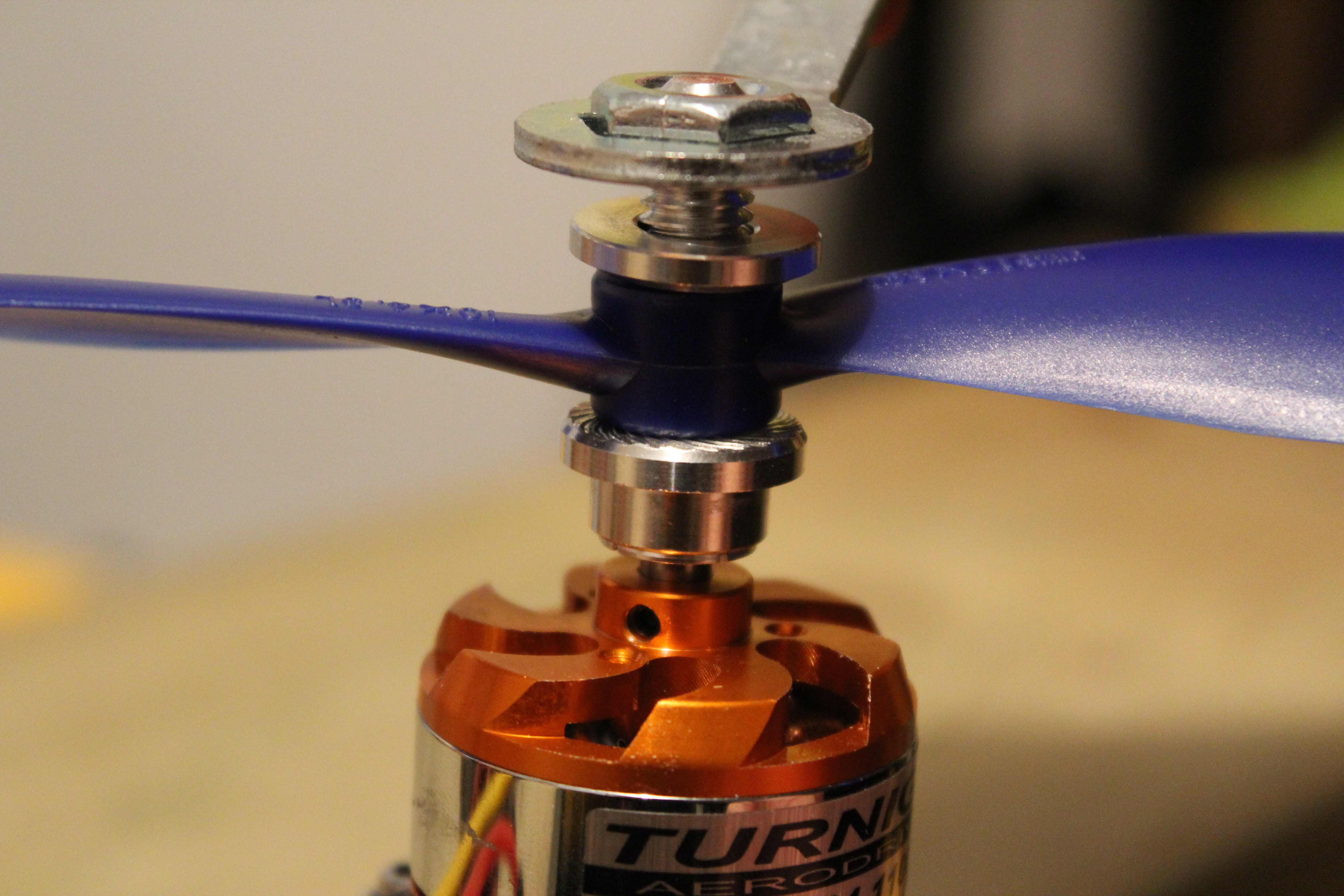
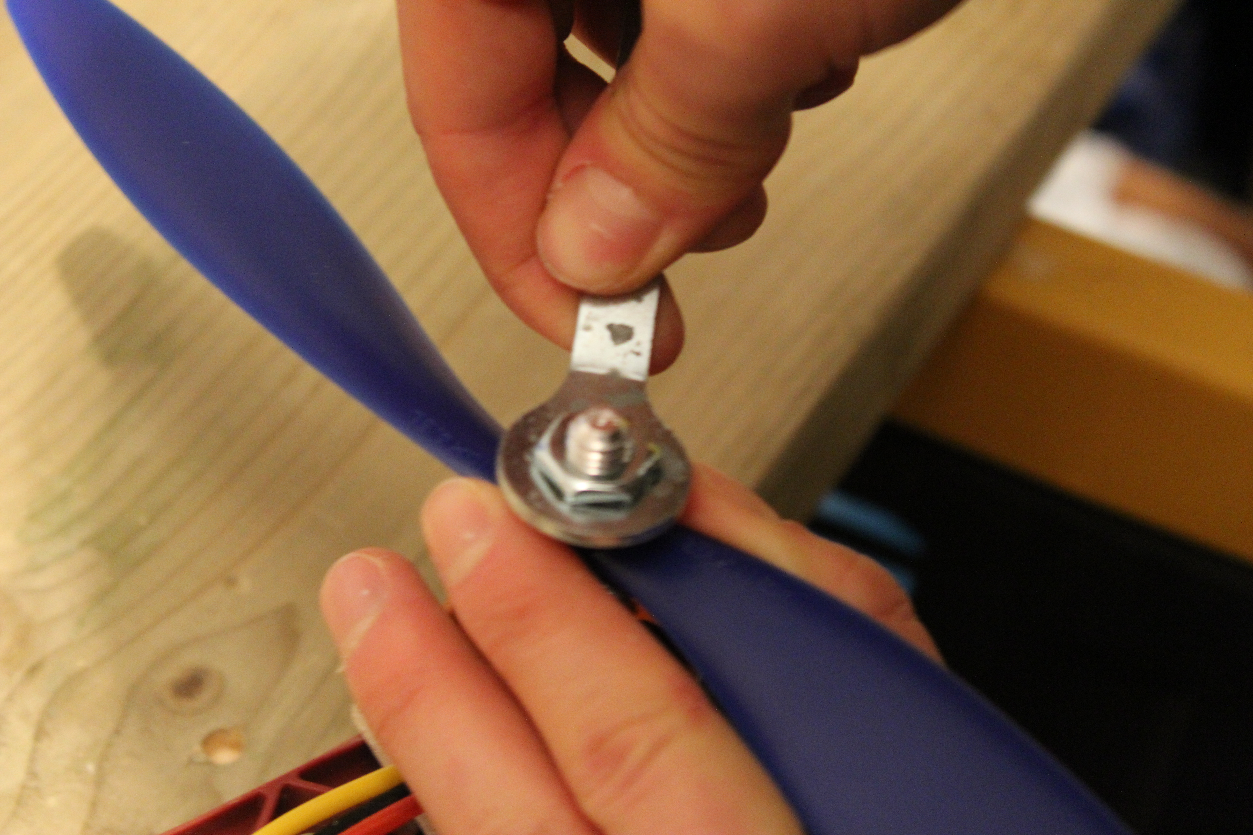
- Drill the propellers and put them on the motors with the help of the special bolt that come with the motor
The Connections
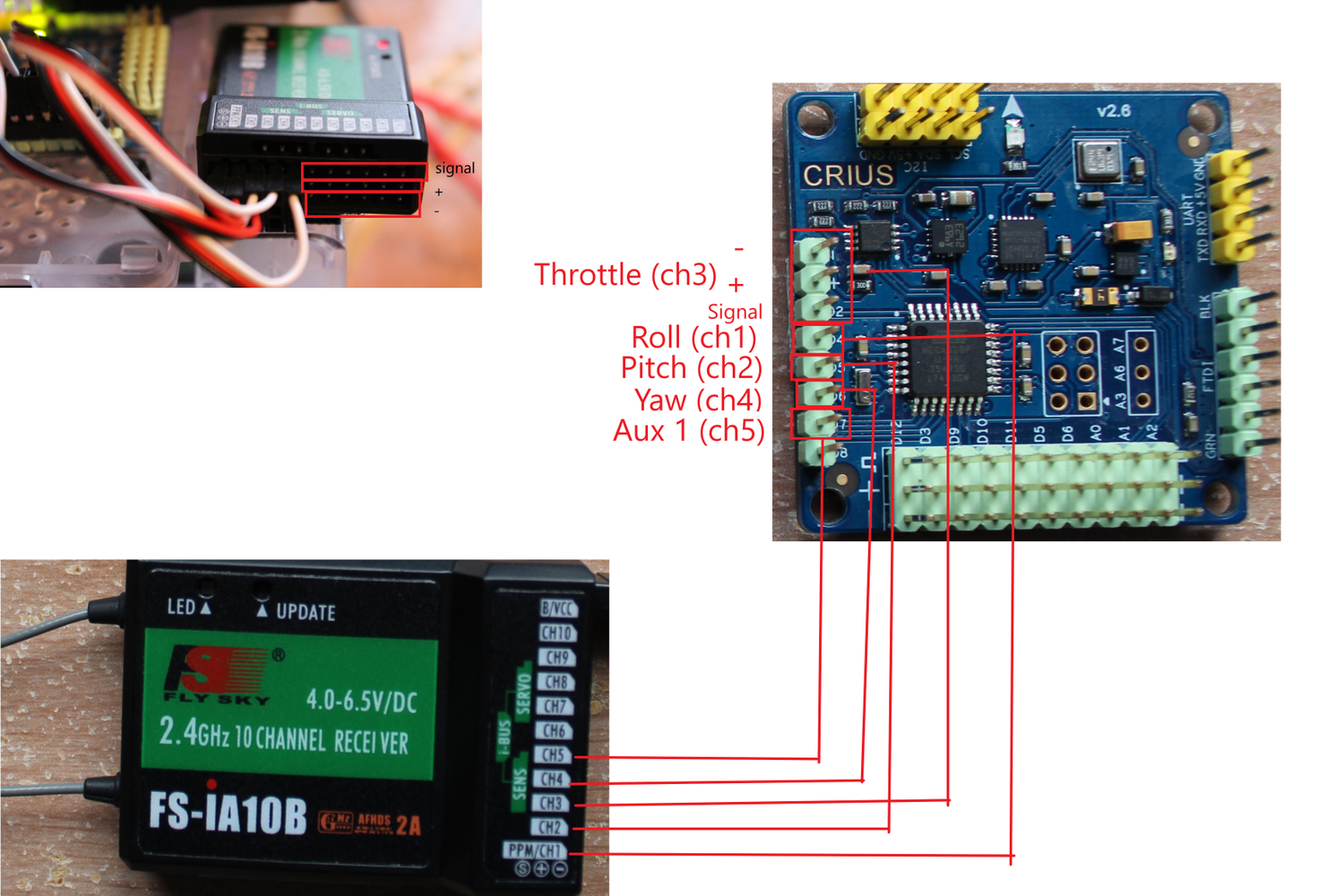
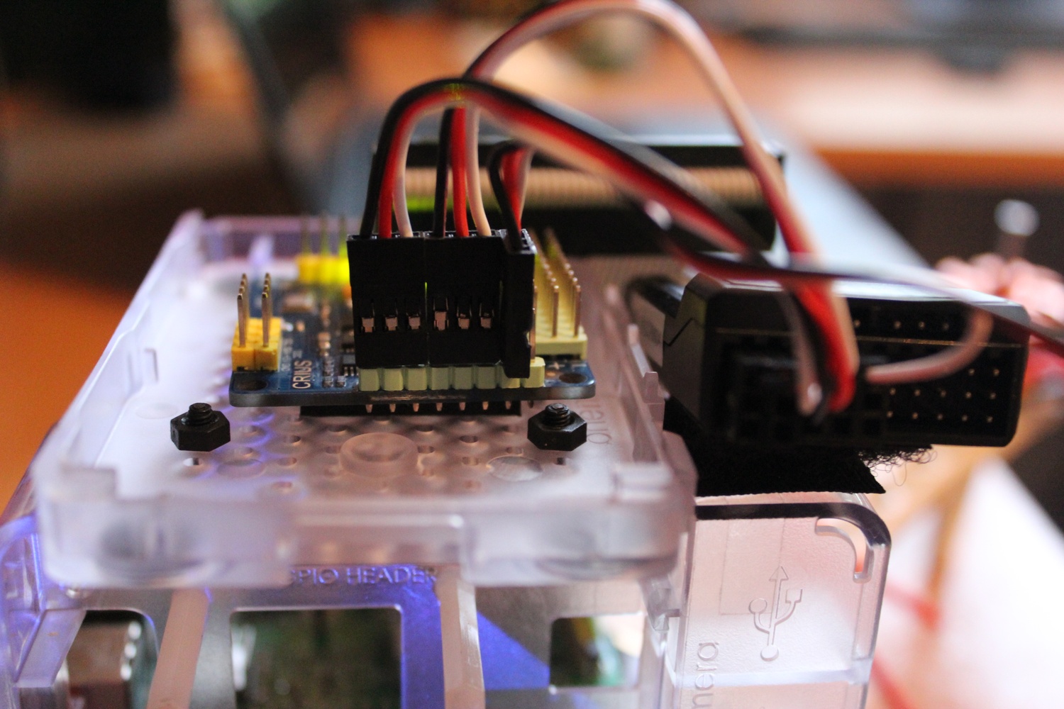
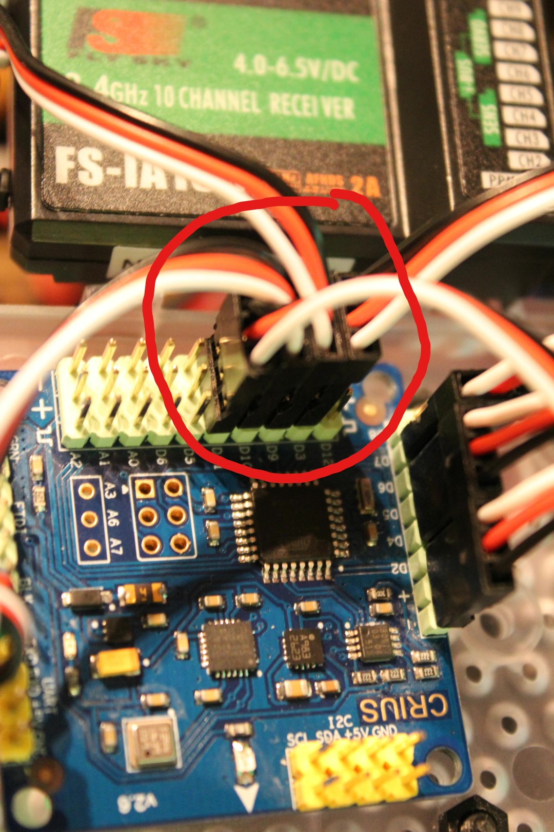
For the receiver:
- Connect Throttle pins on the MultiWii to channel 3 on the receiver.
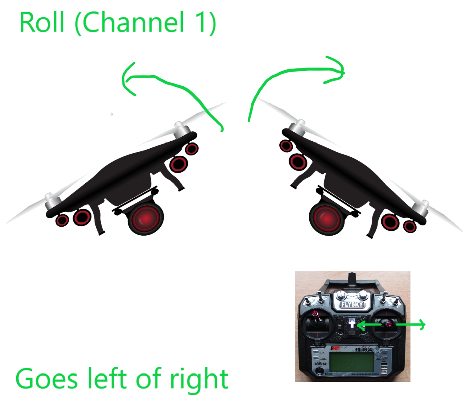
- Connect Roll pins to channel 1 on the receiver.
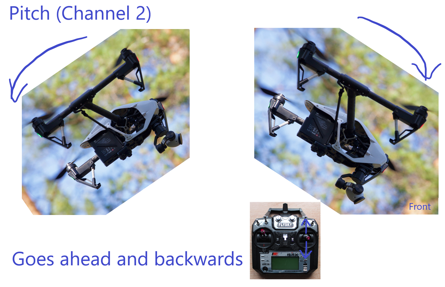
- Connect Pitch pins to channel 2.
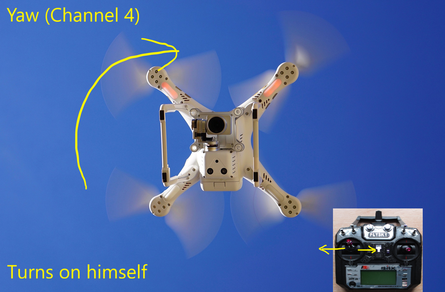
- Connect Yaw pins to channel 4.
- Connect Auxiliary 1 to channel 5.
For the ESCs:
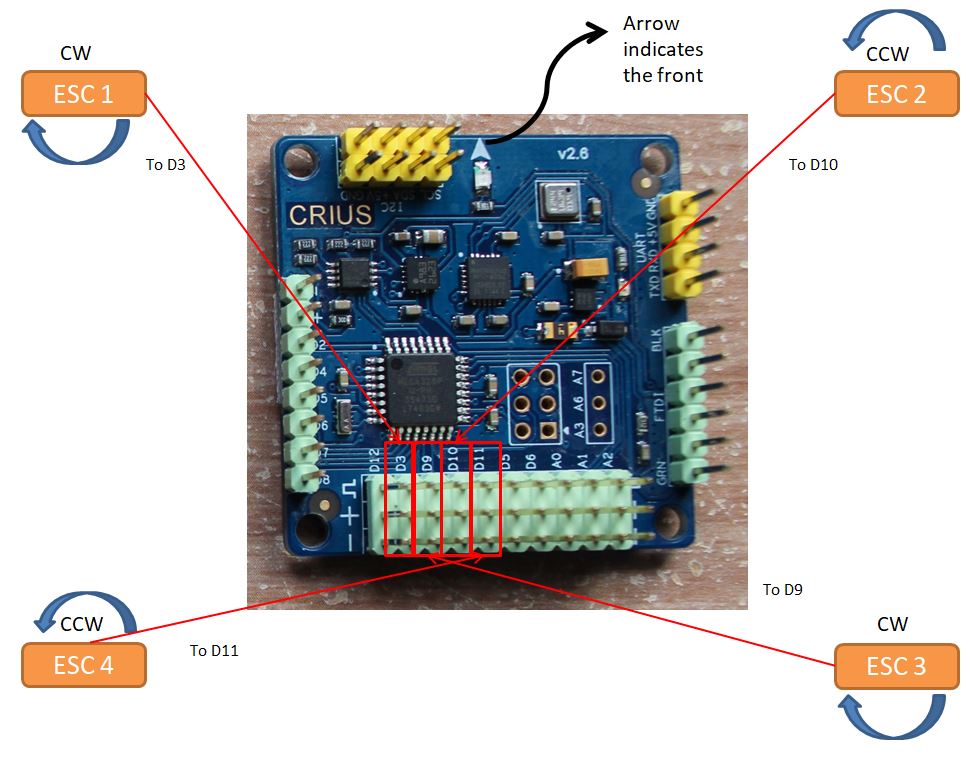
With Multiwii facing forward and with black wire of the ESC's command connector's on the bottom pin of the Multiwii;
- Connect the left-upper ESC to D3.
- Connect the right-upper ESC to D10.
- Connect the right-bottom ESC to D9.
- Connect the left-bottom ESC to D11.
For the Pi:
- Connect the PiCamera.
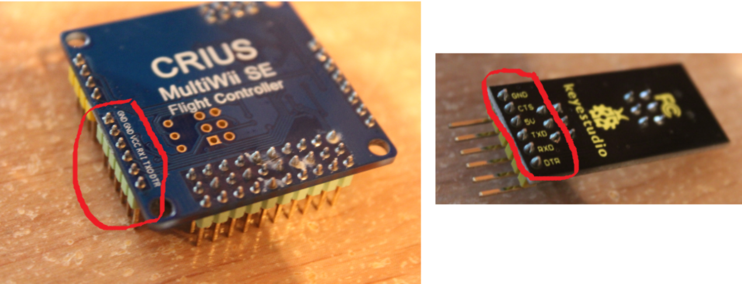
- Connect the FTDI to a mini-USB/USB adapter and connect it to the Pi, also connect the FTDI pins o the FTDI pins of the MultiWii.
- Connect a - and + pin of the MultiWii to a 5V and ground GPIO pins of the Pi.
For the motors:
By default, the motors rotate in counter clock wise (CCW) direction. So for the upper-left and the bottom-right motors, you need to invert the wires connection with the ESC (the black with the red and the red with the black) therefore you will have a clock wise direction (CW).
Configure It All
Remove your propellers for the following steps.
Programming the ESCs:
The electronic speed controller controls the motor and therefore a lot of options are available and it is up to you to customize your ESC so it behaves as you wish.
Remove all the wires connected to the receiver.
For each ESC:
- Connect only one ESC to power (to the distribution board in our case) and make sure the battery is disconnected.
- Put the ESC pin's in throttle channel of the receiver (in our case channel 3).
- Power up your transmitter.
- Put the throttle to maximum position on your transmitter.
- Power up the distribution board by connecting the battery to it. You can also use some alligator clips and connect directly the battery to the ESC.
- After some beeps, you should hear a musical tone with 4 beeps. After this first music put throttle at minimum position on your transmitter.
- Wait confirmation from the UBEC, given by a beep.
- Close the transmitter.
- Remove the power (disconnect Li-Po battery)
To test it :
- Power up the transmitter with minimum throttle position.
- Connect the battery.
- Gradually increase the throttle to maximum power. The motor should spin faster when you increase throttle.
Setting up the flight control board:
For this step you can remove the USB cable of the FTDI on the Pi and put it in your computer, that will be more convenient to program the board.
- Download the Arduino sofware on your computer via the website.
- Download multiwii firmware latest version and extract it on your computer.
- Go in the folder MultiWii previously extracted, then open MultiWii.ino who will lauch Arduino.
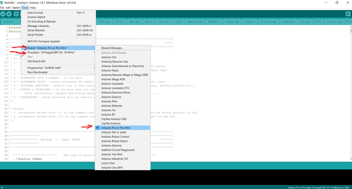
- Go to the config.h file in Arduino, remove // in front of #define QUADX to setup the type of configuration of your multicopter and in front of #define CRIUS_SE_v2_0 to choose the type of board.
- Then go in Tools -> Board -> and select Arduino Pro or Pro Mini and make sure in Tools -> Processor -> that ATMmega328P (5V, 16MHz) is selected.
- Last configuration we need to do before uploading on the board is to go in Tools -> Port -> select the port of your MultiWii (COM3 for us).
- Click on verify and then on upload.
- As the code is uploading on the Crius MultiWii SE v2.6 you should see the lights flashing on both the controller board and the FTDI board.
Calibrate the sensors on the flight control board:
- Go to the MultiWiiConf folder present in the MultiWii folder downloaded previously from their website.
- Then go to -> application.windows32 folder -> double-click on the MultiWiiConf application. (Note that even if I had windows 64bits only the 32bits app seems to work).
- You need to select the port to which your flight controller is connected to (in this case COM3).
- Click on Read.
- Click on Start.
- Put your board flat on the desk and then click on Calib_acc.
- Click on Calib_mag and then you need to rotate your board in all direction during 30 secondes as fast as possible. You should see spikes all over the graph.
To test it :
- Rotate your board on the pitch, roll and yaw axis and see if what the sensors show on the software makes sense.
Setting up the transmitter (remote control):
First, you can verify which stick controls which channel in the Display Menu :
- Before you start the controller, make sure all switches are up and that the throttle stick (left stick) is down.
- Start the controller.
- Hold Ok button.
- Go in Setup, then Display.
- You can move your sticks to see which channel reacts.
Before going further, select a model and a name:
- Go in System-> Model select -> select a model.
- Go in System -> Model name. And give it a name. Hold on cancel to save your changes.
- Go in System-> Type select and set it as an Airplane or glider even if it is a quadrirotor.
- Set trim in Subtrim Menu. When the sticks are in their neutral position you need the channels (see in Display Menu) to be at 0% for the yaw, pitch and roll.
- Hold on cancel to save your settings.
Next, lets set the Failsafe settings:
This ensure that when the drone goes to far from the controller and lost signal, that all the controls goes to neutral position. So to do this, we need to set channel 1 ,2 and 4 to 0% and activate failsafe on them via Failsafe Menu. We also need to activate failsafe on the throttle and set it to 100%.
You can also use the other switches on your controller by activating them in System-> Aux. switches.
You can have more details about this section on our website.
Live Stream
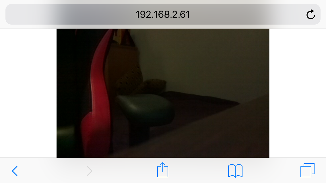
The Raspberry Pi is a computer and what you can do with a flying computer has limit just your imagination.
To live stream:
- Enable the PiCamera. To do so, start the Pi and connect a mouse and a monitor to it. Click on the rasbian logo on the top left, go in preferences, then Raspberry Pi Configuration and then in the interfaces tab make sur Camera is checked as enabled. Then click on ok.
- Download the script (source of the code: random nerd tutorials) and put it on your home folder.
- Run the script by typing ''python3 rpi_camera_surveillance_system.py'' on the terminal.
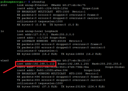
Once the script is running you can access your video stream web server at : http://:8000. Replace with your own Raspberry Pi IP address, in my case http://192.141.1.112:8000.
If you don’t know your Pi IP Address, you can know it by typing ifconfig in the terminal which gives you the address.
You can access the live streaming via any device connected to the same network as the Raspberry Pi. You just need to open the browser.
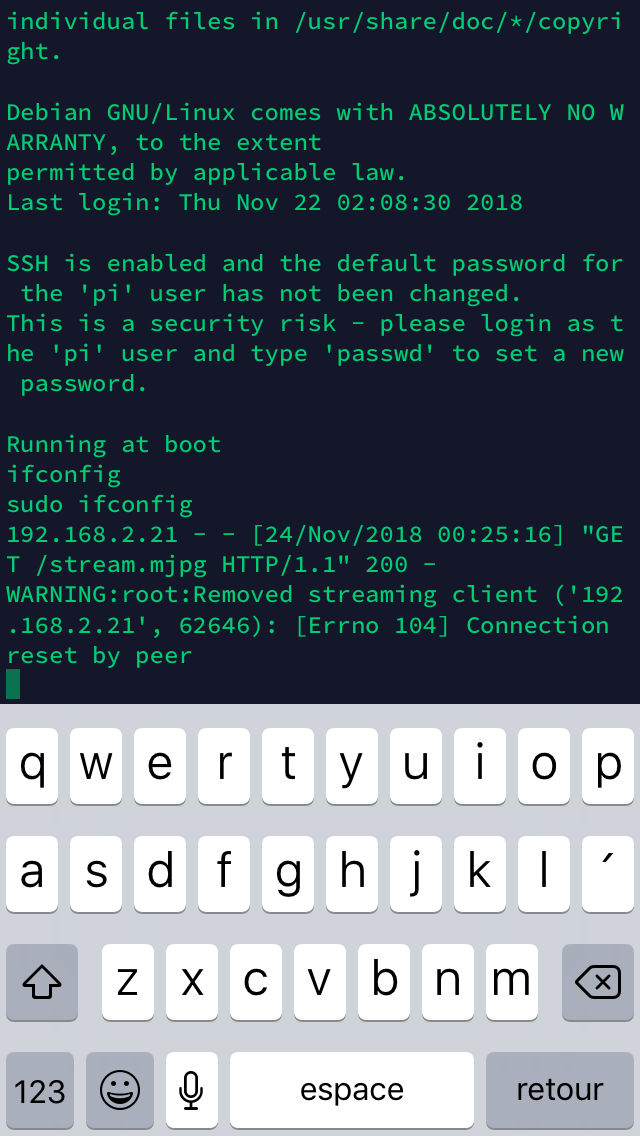
You can also launch this program from your smartphone. You just need to install Terminus app (if you have an IPhone).
To launch the stream directly when the Pi is powered (so when your drone is on) type on the terminal:
sudo nano /home/pi/.bashrc
Then go at the last line and add,
echo Running at boot
sudo python3 /home/pi/ rpi_camera_surveillance_system.py
sudo reboot
Save your file by pressing Ctrl+X, then type Y and click on Enter.
Congratulations, you live stream is now set! You can use it to spy on your neighbors or do some FPV racing!
Downloads
The Art of PID Tuning
You are ready for your first flight. First thing you should do is to try out your drone without any propeller to see if everything responds well.
Then, you can add your propellers and start very slowly to increase the throttle to see if you can take off.
Your drone probably oscillate slowly, vibrates or the motors whistle. This means you need to set up your PID settings!
This part takes a while if you want a very stable drone that responds well to your commands. PID setting is subjective so it's really up to you how you want your drone to fly. Here is the procedure:
- Start with a low I on pitch and roll (0.01) and increase P until you see high frequency oscillations and reduce it back to the last value.
- Then, increase I on pitch and roll by increments of 0.01 until again you see vibrations or you feel your drone is stiff and unresponsive. Typically the I setting can help you if you experience altitude drops and drifting. It counters the perturbations on your system (the drone).
- Lower back your P if you saw any high frequency oscillations.
- Decrease your D if your drone seems too dampened (low to respond).
For the yaw axis, typically you can leave it at default but if you feel that your drone drifts in the yaw axis, then you can increase I.
Follow Me Feature
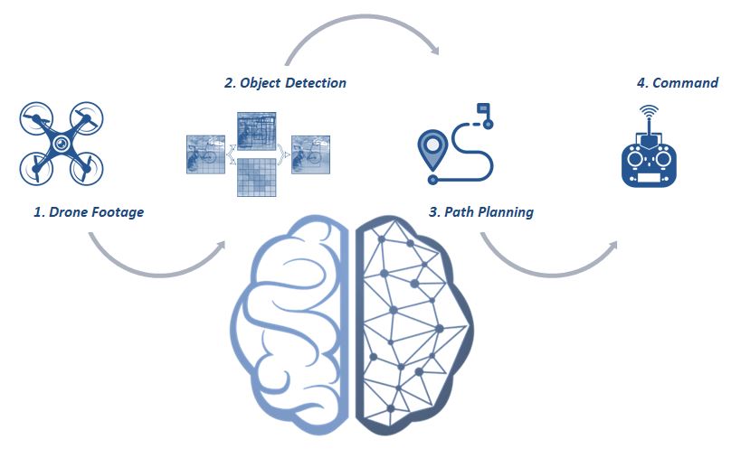
An autonomous drone is awesome, it can fly and move without having to worry about it.
The drone done in this tutorial has the ability to do this by processing the data that his sensors capture.
To implement a feature such as person tracking you need to:
- Use the drone's camera to help him take note of his environnement.
- Use an artificial vision algorithm to analyse the environnement.
- Plan the drone's trajectory.
- Command the direction to follow to the drone.
More specifically, the Pi Camera can provide a live stream of images to the Raspberry Pi who is a computer with enough power to run some artificial vision algorithms.
These algorithms can detect a person in a picture and analyse the position of this person. Haar cascade algorithm or deep neural networks can be useful algorithms for that.
Therefore, by knowing the position of the person to follow, you can plan how the motors move and which direction to take depending on the position of the tracked object in the frame. For example, if the person to be tracked is on the right of the frame taken by the Pi Camera, the algorithm command to the drone to turn right.
Finally, once the direction the drone should follow has been chose, the Raspberry Pi has to send a command to the Multiwii to permit to the drone to go in that direction. To do that, the MSP (Multiwii Serial Protocol) is useful to communicate between your computer (the Pi) and your flight controller.
Here you can find attached a way how to code that.
A more robust method using tensorflow and deep neural networks for person detection has been shown on our website.
You can also imagine a lot of other ways to enhance your autonomous drone, like making him take a photo of every time he sees a tree or an animal. Object avoidance is also possible to implement you just have set the drone to stop his race if he is closer than a specified distance from an object.
Also, you can learn on the website how to connect an LED to the Pi and turn it on when the drone detects someone to follow!
Happy Flying!
Start up your drone and enjoy your fly.
If you want to go further and implement person tracking on your drone, you can consult our website for a tutorial on that.
Thanks you for ready this tutorial!