Foam Robot
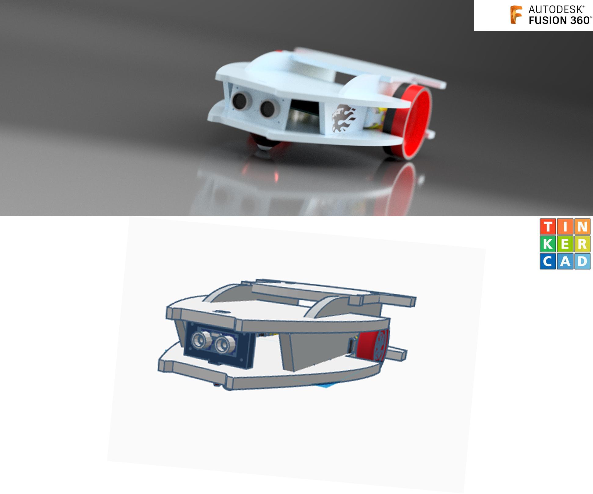

I am not very good with CAD designs, but love playing with it. Last year I had built a Bluetooth Foam Robot using Tinker CAD. My Robot contains a Battery Charger Section, Arduino Board, HC-06, Ultrasonic Modules and couple of Single Shaft DC Motors. It was a hassle for me to do the wiring. Wires used to get tangle often and also it used to consume lot of time in troubleshooting.
In this Instructables I would be using my Foam Robot designed in Tinker CAD as a reference and would be creating a PCB and CAD Model in Fusion 360.
Earlier I used to work with Tinker CAD, but Fusion 360 is a killer. It has lot of 3D CAD Models, more tools and has lot of features (Rendering , Animation, Manufacturing drawings , Schematic/ PCB Design etc).
Supplies
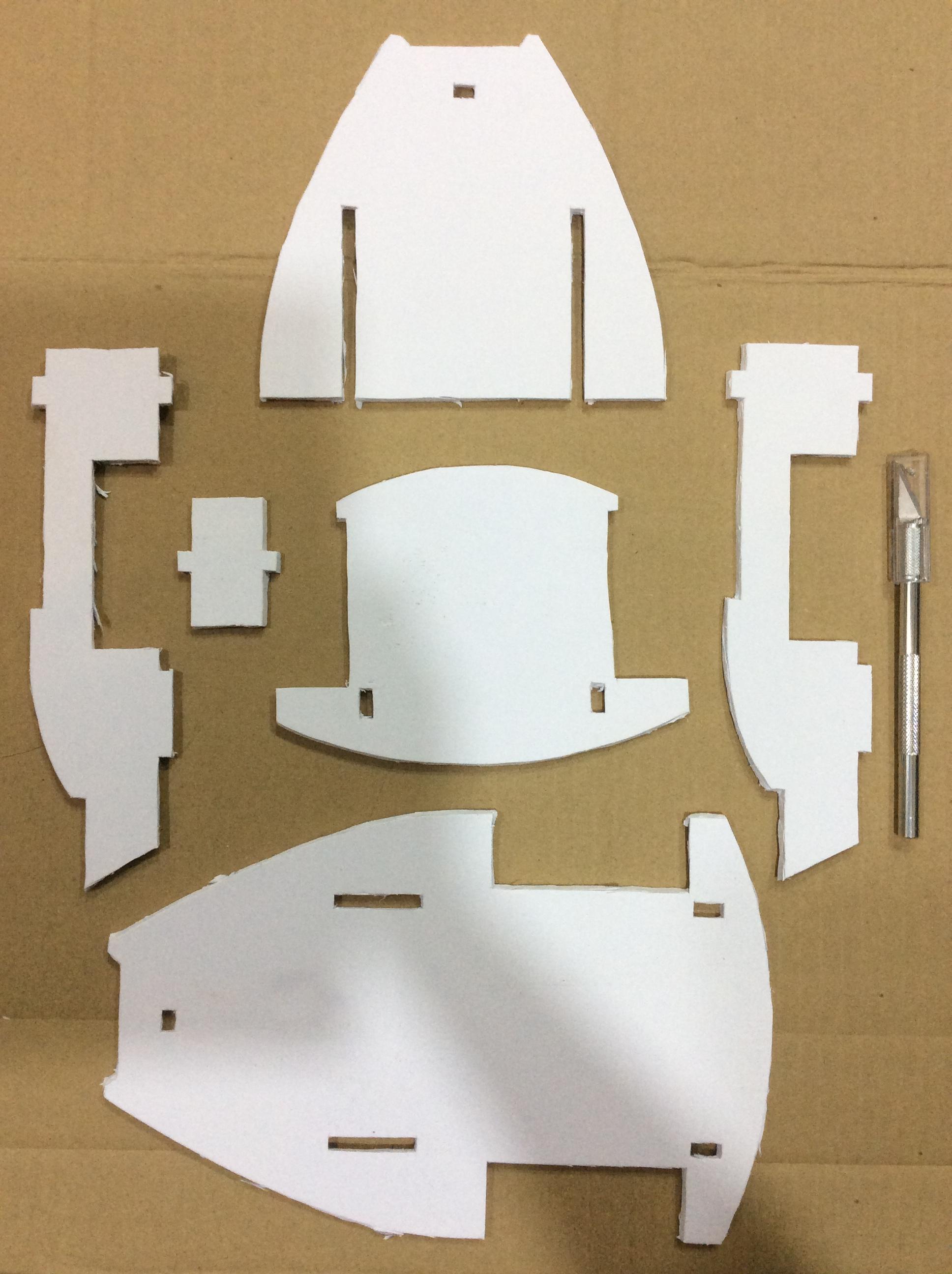
Supplies:
Fusion 360
TinkerCAD
Foam Board
X-Acto Knife
Tinker CAD Design Model
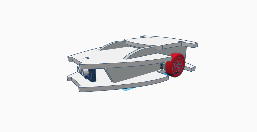
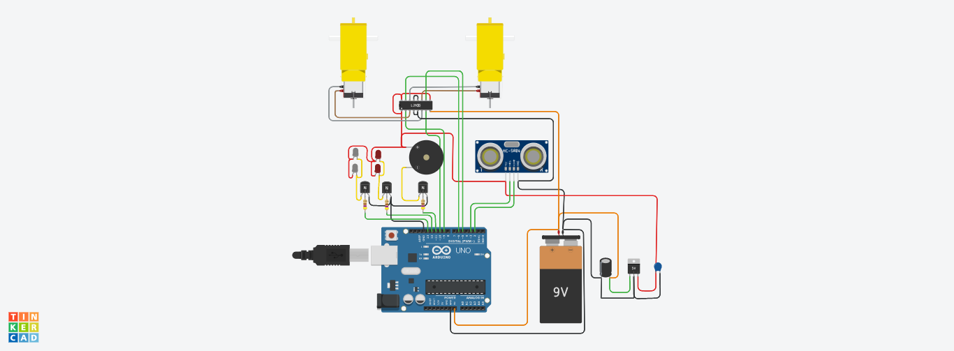
In the Photo, you can see my earlier Tinker CAD Designed Model. I was happy with my designed Model. I also made the Circuits in Tinker CAD only.
If you can see in the Picture, I have used 9V battery, In reality in my prototype I have used couple of 18650 battery with recharging functionality. But here in the Tinker CAD I have put 9V battery due to it’s limitation.
There were lot of limitations in Tinker CAD I had faced No history tree, Web program hangs often when using it, you have to work with plain colors No Rendering feature available, limitations in components list etc.
Link for the TinkerCAD Model
Link for the Circuit in TinkerCAD
Schematic and PCB Design
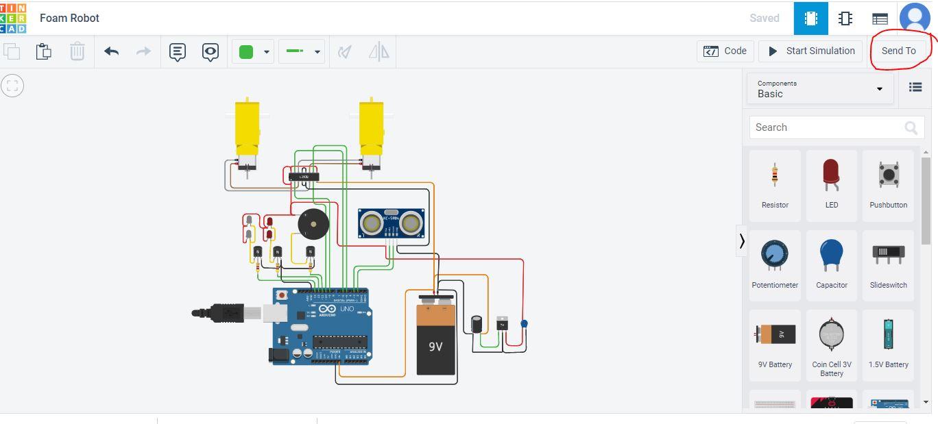
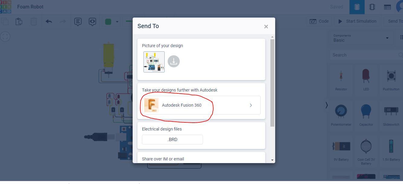
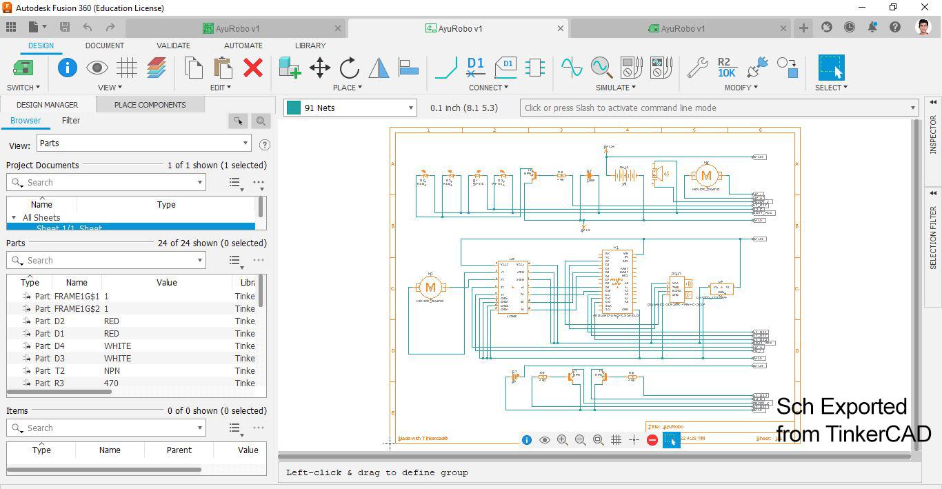
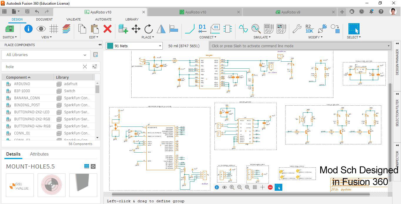
Firstly, I wanted a single PCB for my Robot which directly fits inside it. This would make my robot make modular and look beautiful, also there would be no wires coming out so almost No troubleshooting required.
There was a cool feature in TinkerCAD, where you can take your Designed Circuit in TinkerCAD to Fusion 360 (see photo).
Click on Send To -> Autodesk Fusion360.
All my designs got exported to Fusion 360 Schematic and PCB. I started creating the Schematic. It was new for me using Eagle. It took me lot of time making the just Schematic. For Beginners initially you would face lot of problems, but soon you will gain speed as you go on using it.
If you compare the Schematic generated by the TinkerCAD and the one modified by me in Fusion 360, you will see lot of changes in it. I redesigned the whole Schematic as per my needs. I have attached all the necessary files of the Schematic ,PCB and also included the BOM.
Before going to the PCB Design. I first completed my CAD Design in Fusion 360.
CAD Designing
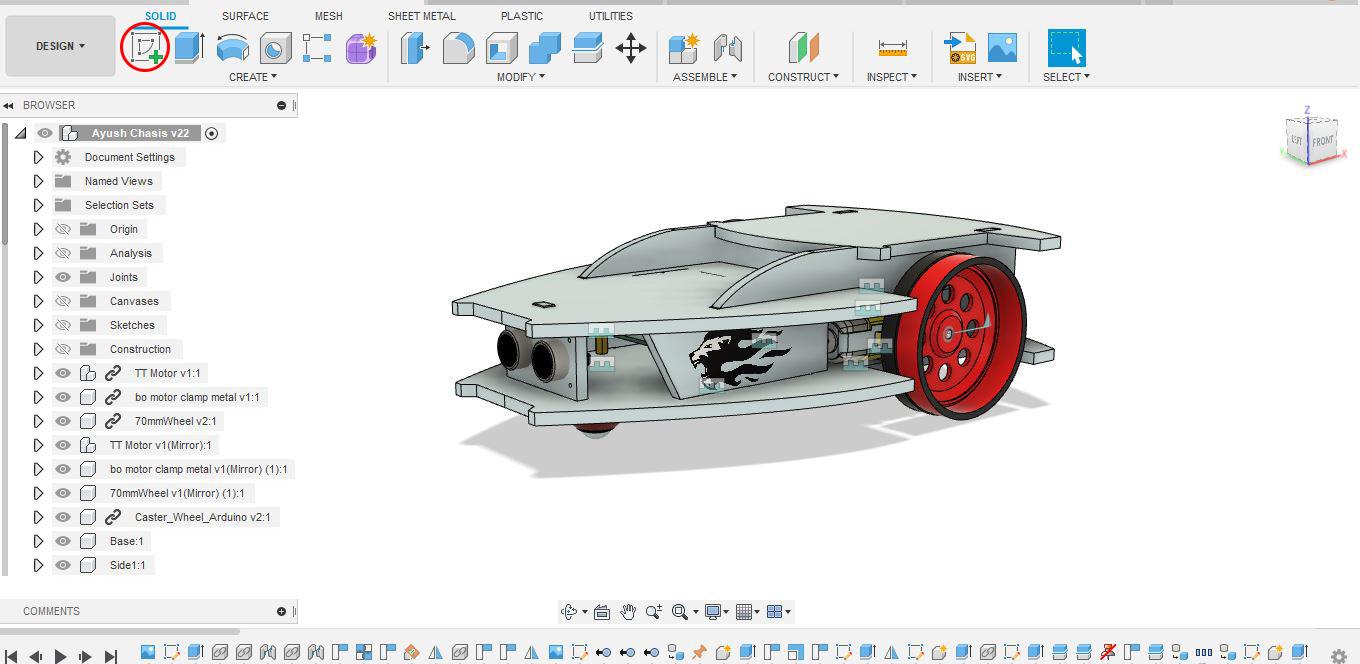
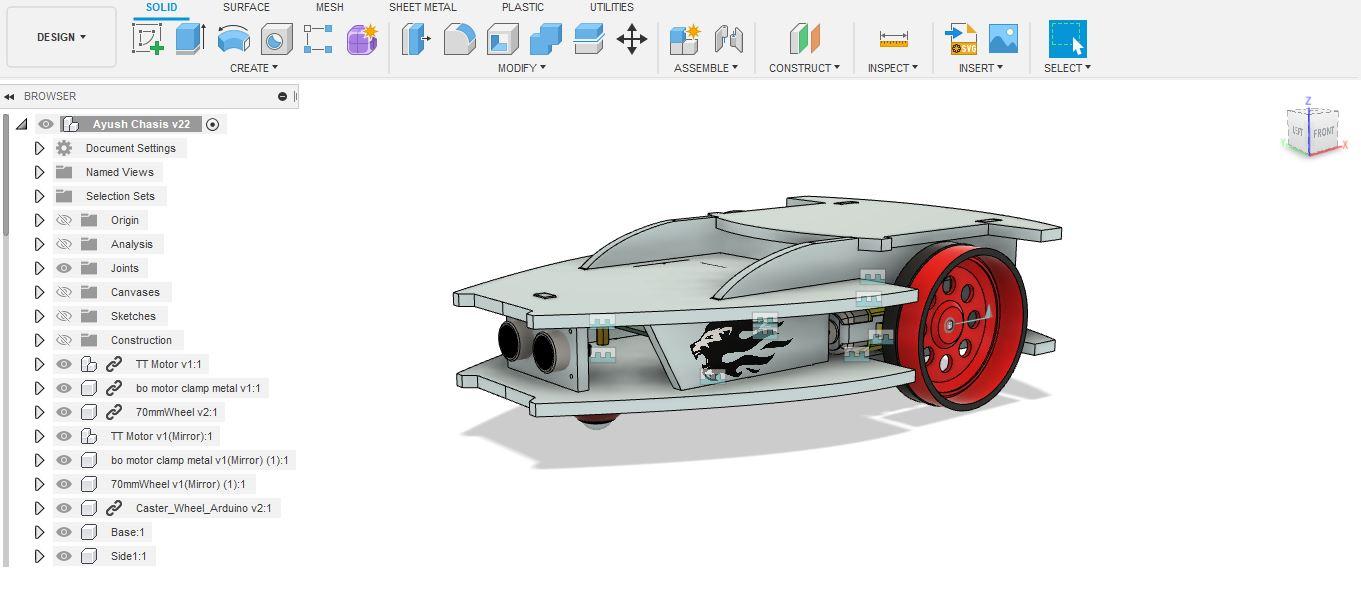

I added lot of things inside my designed CAD. Added wheels, brackets for the motors, decal etc. I have attached all the necessary files that would be required for you to go along.
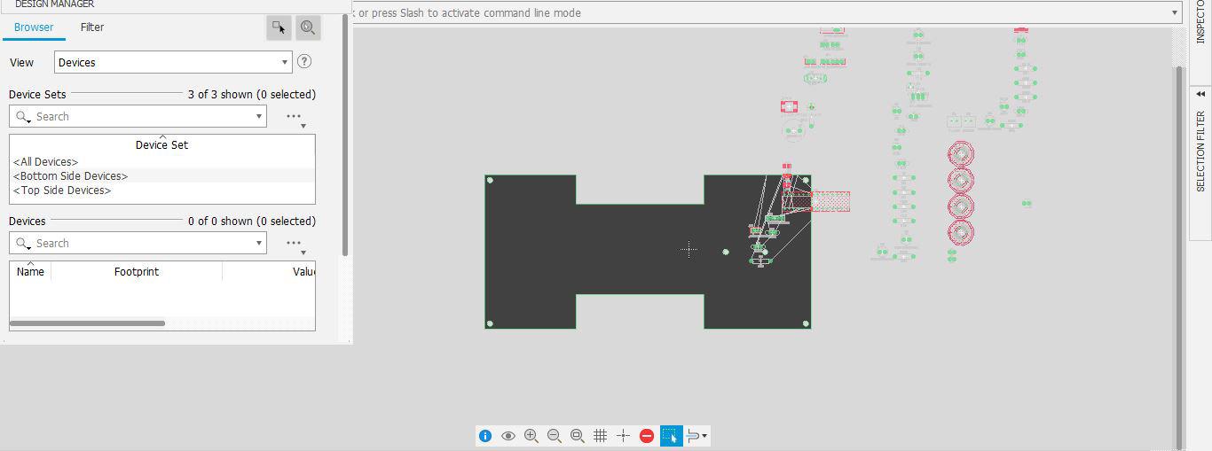
The best part you can assign shape of the PCB in Fusion 360 sketch and then export that sketch to PCB 3D and from there you can link that 3D PCB to the PCB in which you would be doing the placement and layout.
First Create the shape of the PCB using "Create Sketch"
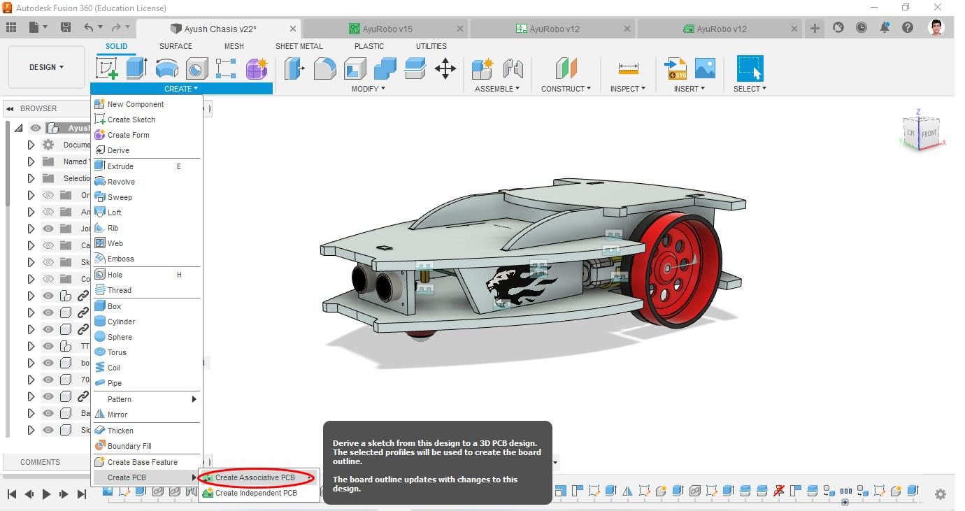
Goto: Create -> Create PCB -> Create Associate PCB -> Select the sketch that you want the PCB shape to be.
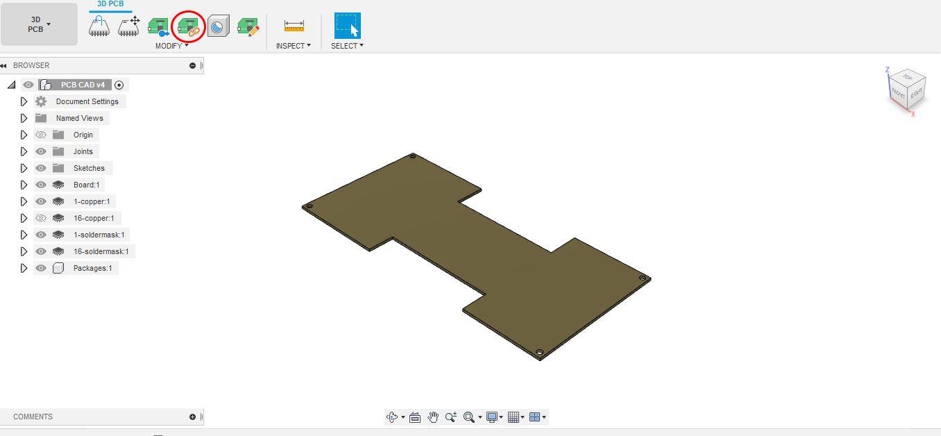
Voila !! it would generate the 3D PCB Board. Inside the 3D PCB
Click on Link to 2D PCB. Choose your 2D PCB Board and you will have your custom board shape in your PCB Design.
Rendering and Animation


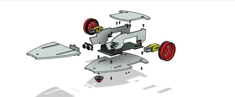
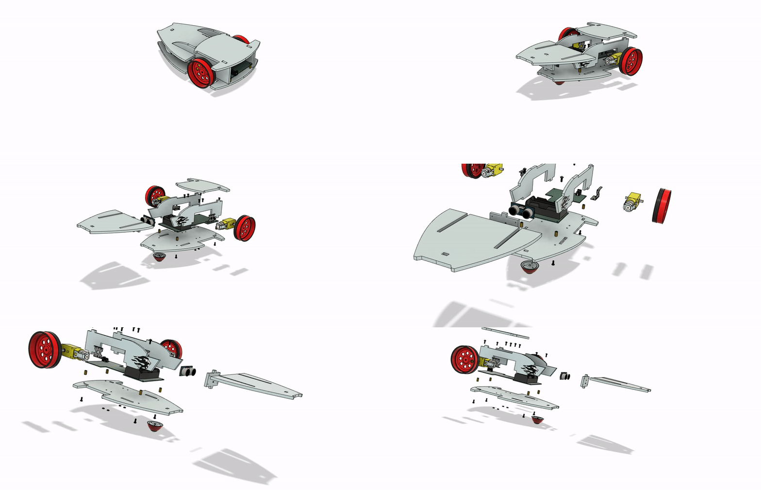
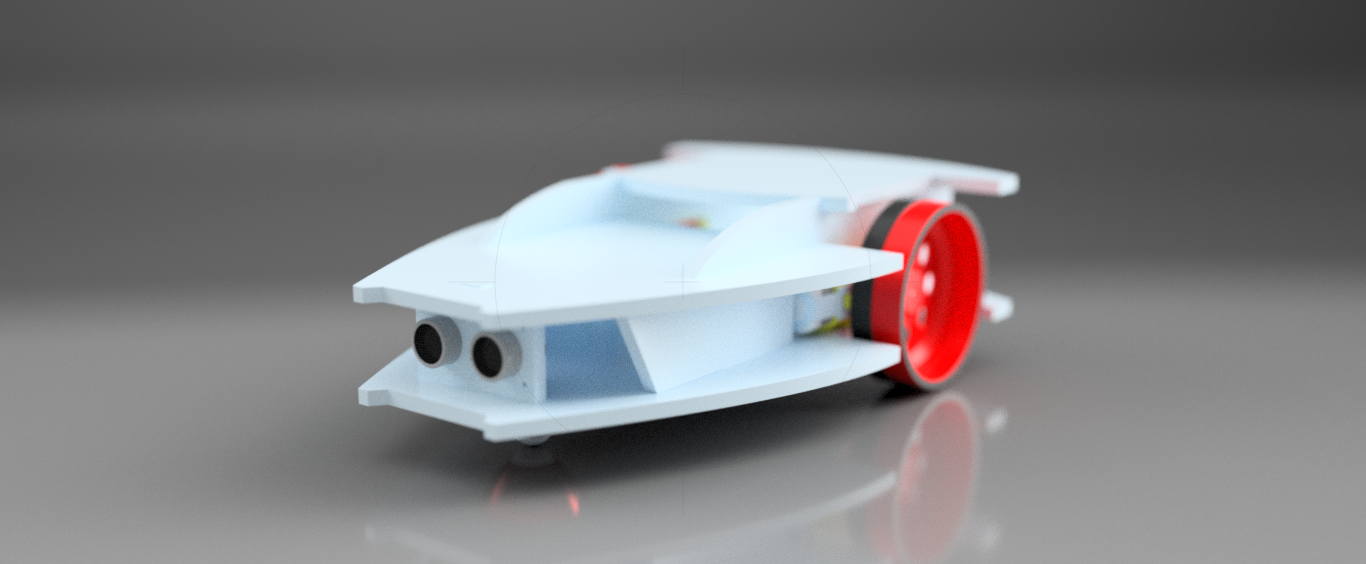
I then Rendered my CAD Model by adding some Decals to it. It just looks awesome. Also I animated my Bluetooth Foam Robot to explore some more features.
Assembly
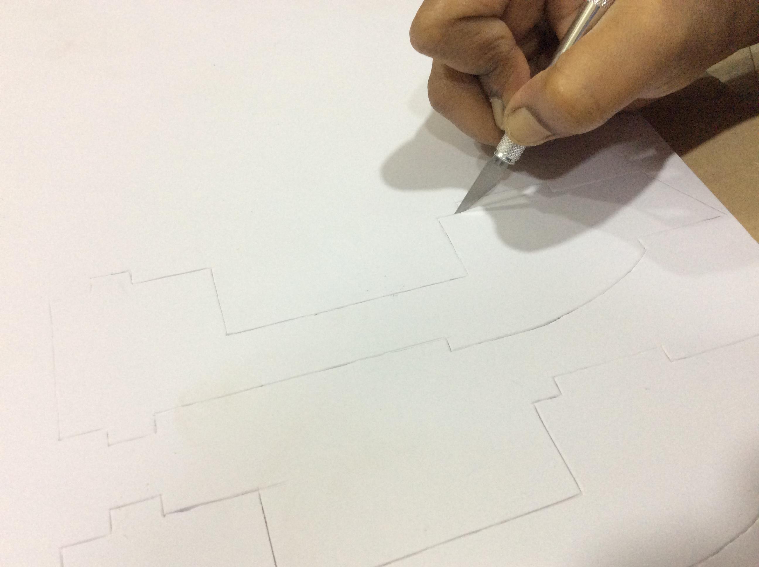
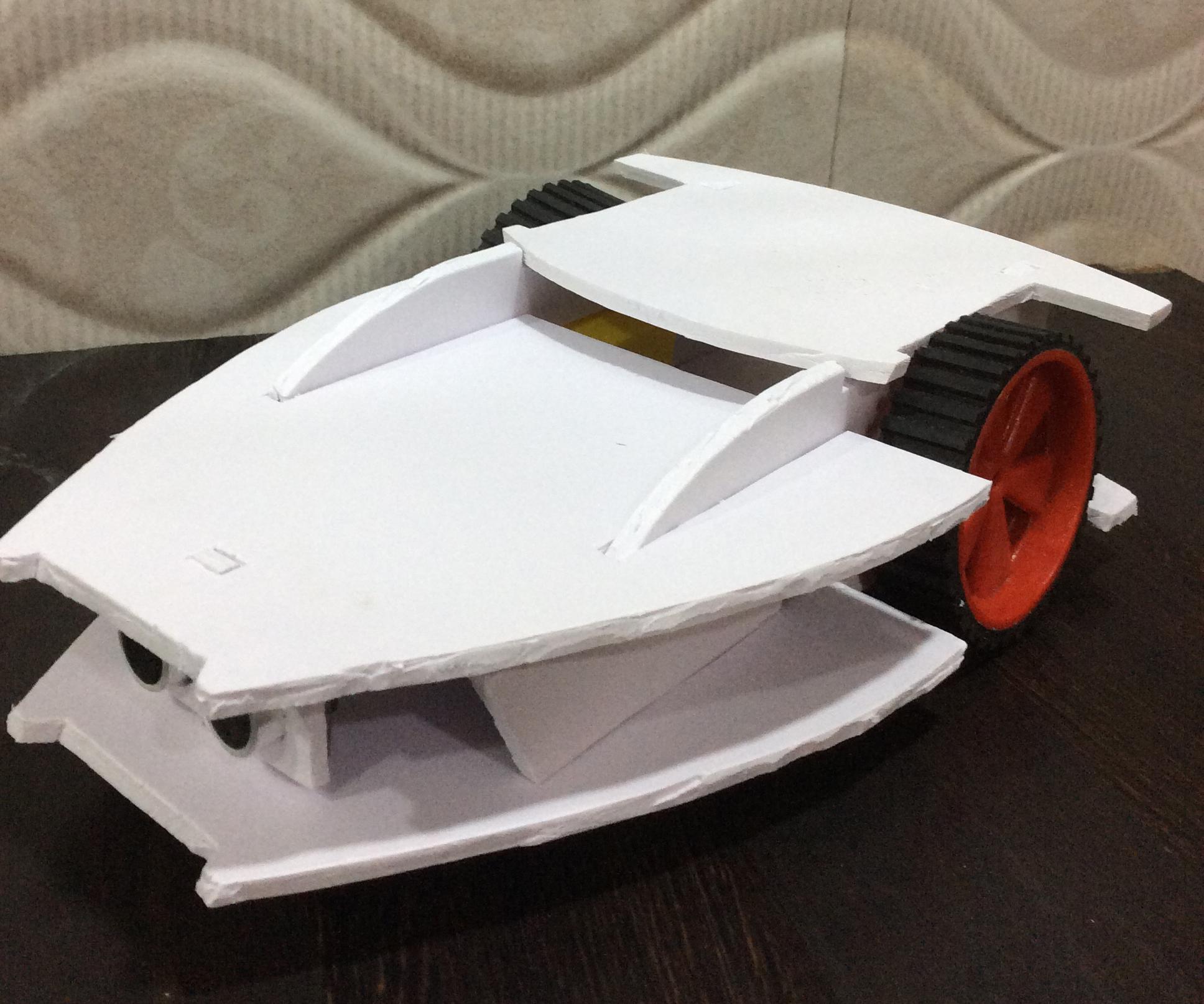
Using X-Acto Knife I cut the shape of the Foam Robot and assembled it. I was satisfied with the results.
Thank You !!!