FlySky Receiver RSSI Mod
by garzo in Circuits > Remote Control
12713 Views, 11 Favorites, 0 Comments
FlySky Receiver RSSI Mod
I begun my drone pilot career using a cheap transmitter made by Flysky, the FS-I6.
It's not that bad to begin with, but sooner or later you will desire something more. You can spend the equivalent of several FS-I6 on a good level transmitter or you can read this ible (and others that will follow) about the mods that i've implemented in my flysky radios.
In this -ible we'll see how to add the RSSI feature to the most common flysky receiver. The RSSI is one big lack in the flysky ecosystem (for whatever unknown reason, since it's really easy to implement). Since the RSSI tells you how good your connection is, and if you are about to loose control, it's quite clear how important this feature is!
Please note that every "flysky" string could be replaced with "turnigy". As far as i know both the transmitter and the receivers are clones. I haven't tested every combination but i'm actually using a turnigy IA6C modded receiver with my FS-I6 without any issue.
COMPONENTS

I'm using an FS-I6 transmitter, you can find it on Amazon, Bangood, Hobbyking and in other stores.
The receivers that can be modded are:
FS-IA6B: Amazon, Bangood, Hobbyking.
FS-X6B: Amazon, Bangood, Hobbyking.
FS-X8B: Bangood.
You will need an USB debugger/programmer, the ST-Link V2: Amazon, Bangood.
Beside that you only need to solder few wires and, depending on the receiver, use some small screwdriver to open the case (it will be especially helpful with the transmitter mod).
RECEIVER SETUP
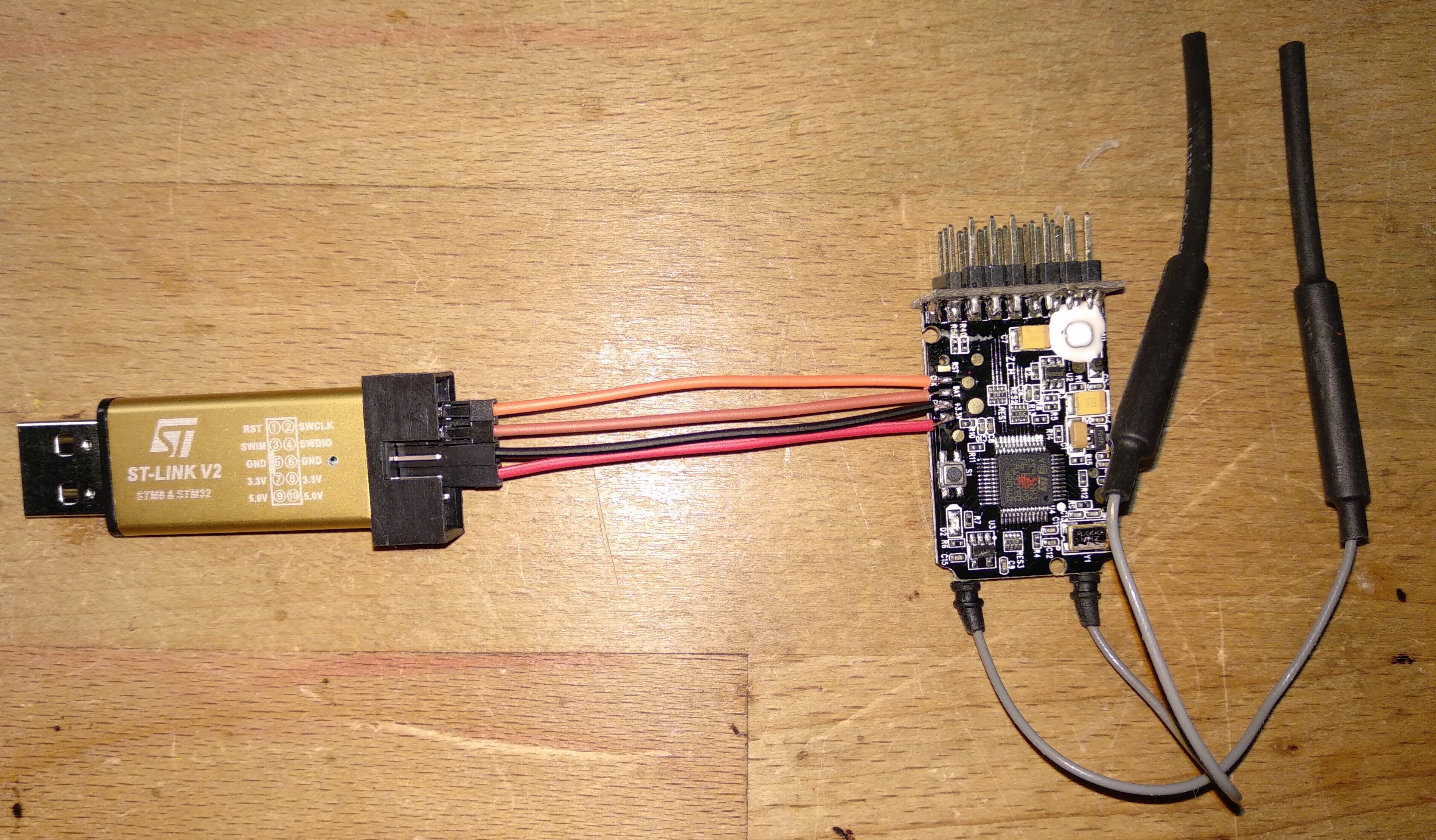
The first step is to remove the receiver's case, if any, and expose it's PCB.
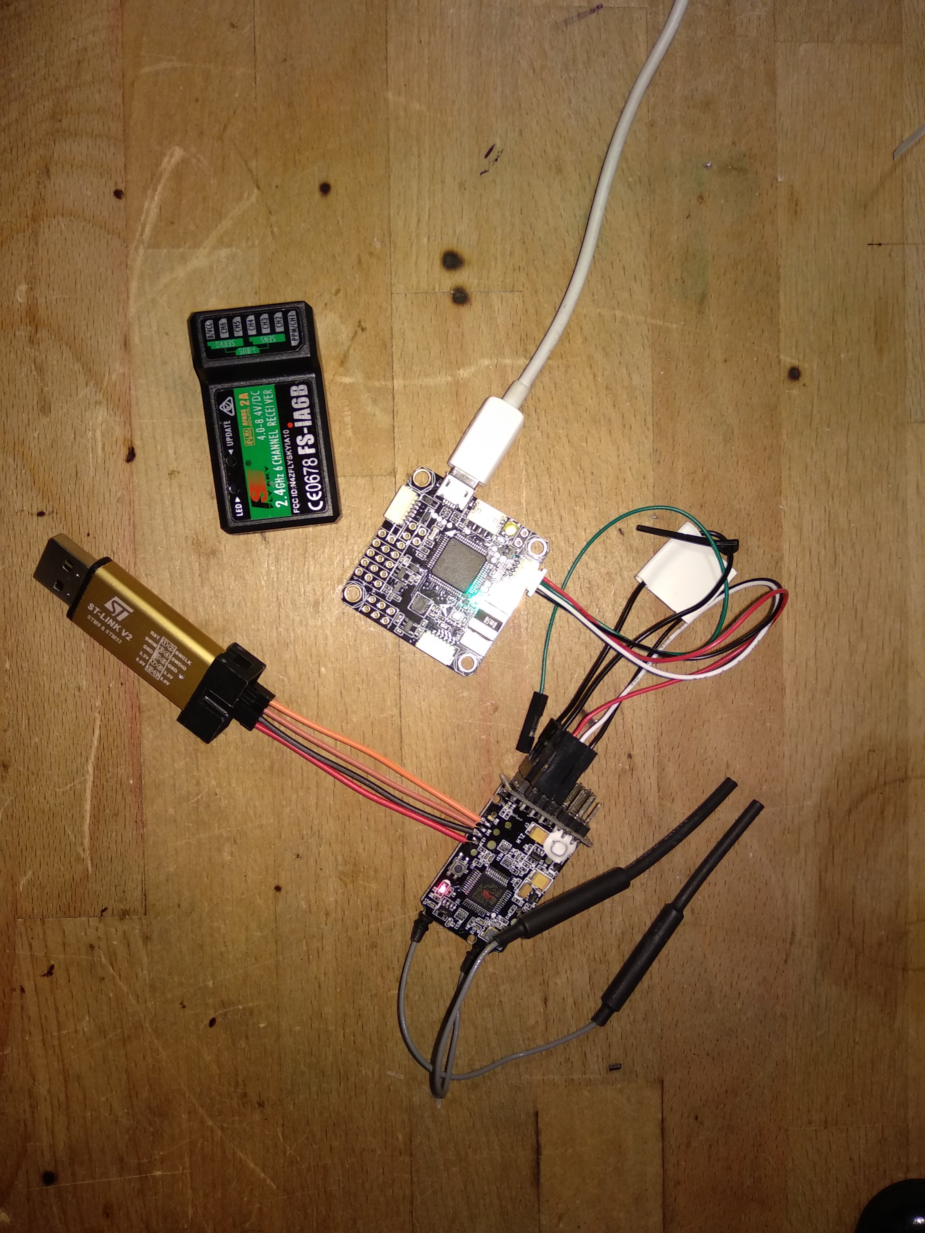
Now, depending on the receiver, you need to find its four connection pads and connect them to the right pins on the ST-Link. I've used the wires that came along the ST-Link, cutting and soldering them in the right place. Some people just kept the wire in place by hand. I don't really support this trick because the chances to short circuit and burn something are way more than the chances to damage the PCB by soldering. The pads aren't huge, but at least they are reasonably spaced, it's not an hard soldering task.
In the image you can see what i did on my IA6B receiver. I put "zoomed" wiring diagram in this page (scroll down, it's not english but you only need to look at the images at the end). There you can find the wiring diagram that i've personally tested and, as soon as i get other receivers, i'll test the mod and i'll update the tutorial.
Pay attention to wire the positive power wire on the 3V3 and not the 5V pin on the ST-Link dongle, it's the bigger chance to damage something.
Once you have somehow connected the four wires (3V3, GND, SWDIO, SWCLK) to the receiver and to the ST-Link you have the device "electrically" ready to be upgraded. Don't plug in the ST-Link USB alreay, you should install the drivers in advance, see the next step.
SOFTWARE SETUP
You need to visit the ST site and download the USB programmer's drivers and utility, they should be the last links/buttons at the bottom of the page. Once you've downloaded them install them, no particular configuration is required.
The receivers' firmwares are provided by Cleric-k and his github repository. He was so kind to provide two firmware for every receiver: one with the RSSI output on channel 14 and one with the RSSI output on channel 8. The only difference is that if you are using a PPM output you should use the channel 8 version, if you are using Ibus output it doesn' matter.
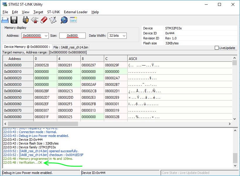
Now open the ST-LINK Utility that you have installed few minutes ago, you should have a window looking like the first image of this step, now follow this checklist:
- Set "Address field" and "Size" to 0x08000000 e 0x8000.
- Click on "Connect to target" (button under the menu).
- Click on "Save" to download a backup of the original firmware (you'll never know...).
- Click on "Open" and find the firmware you've just downloaded from the github repository.
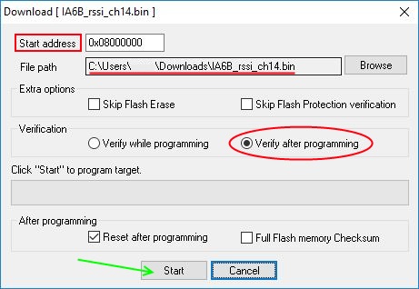
- Click on "Program verify", you should see a pop up window looking like the second image of this step.
- Check that "Address" and "File Path" are correct. They must be "0x08000000" and "your_downloaded_firmware_path".
- Select "Verify after programming".
- Now press start and let the software run.
- If you see the sentence "Verification...OK" in green in the first image console then you have succesfully flashed the new firmware.
If your receiver were binded to a transmitter now the pairing is lost and you have to bind it again. There's a trick that involve an hex editor that lets you manipualate few bytes in the modded firmware (after reading the right values from the orignal firmware) to preserve the pairing but -believe me- it will be way quicker to bind the receiver again. You have it already on the table, with its button exposed.
FLIGHT CONTROLLER CONFIGURATION
Now you have a flysky receiver capable of outputting the RSSI on one channel, it's time to configure the flight controller. It's impossible to do a tutorial for every combination of FC device and FC firmware but luckily the setup is more or less the same. I'll show how to properly set up an Omnibus F4 Pro with Inav firmware.
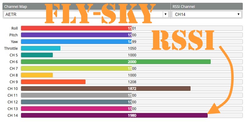
Connect and configure the receiver as usual, PPM or IBUS depending on your requirements. In the configuration tab you have to disable the feature "analog RSSI" (look bottom right). Now go to the "receiver" tab and set the "RSSI Channel" value depending on the firmware you've flashed. I've flashed the firmware IA6B_rssi_ch14.bin (i'm using Ibus output, obviously) therefore i choose "CH14".
That's it: now you have the RSSI function on you flysky receiver!
Someone could have spotted that i'm reading values not only on channel 1 to 6, and my transmitter is supposed to be a 6 channel one. Don't worry, i've modded it to have 14 channel, this will be explained in another -ible. In the meanwhile don't be afraid to follow this tuttorial, the channel number doesn't matter because the RSSI value will be produced by the receiver itself, therefore there's no need to have a modded transmitter to do that.
Happy RSSI to everyone!