Flashlight Tag
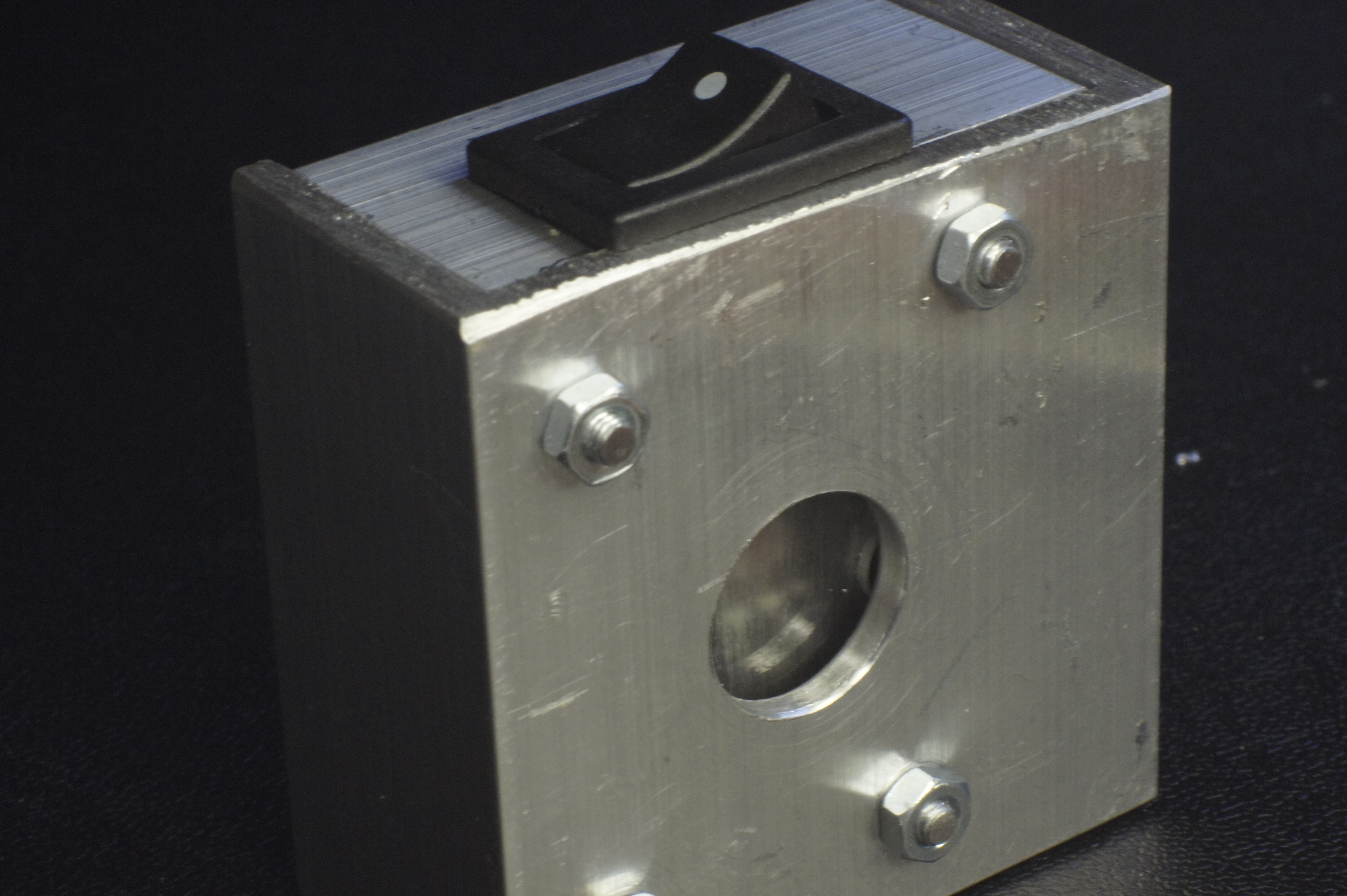
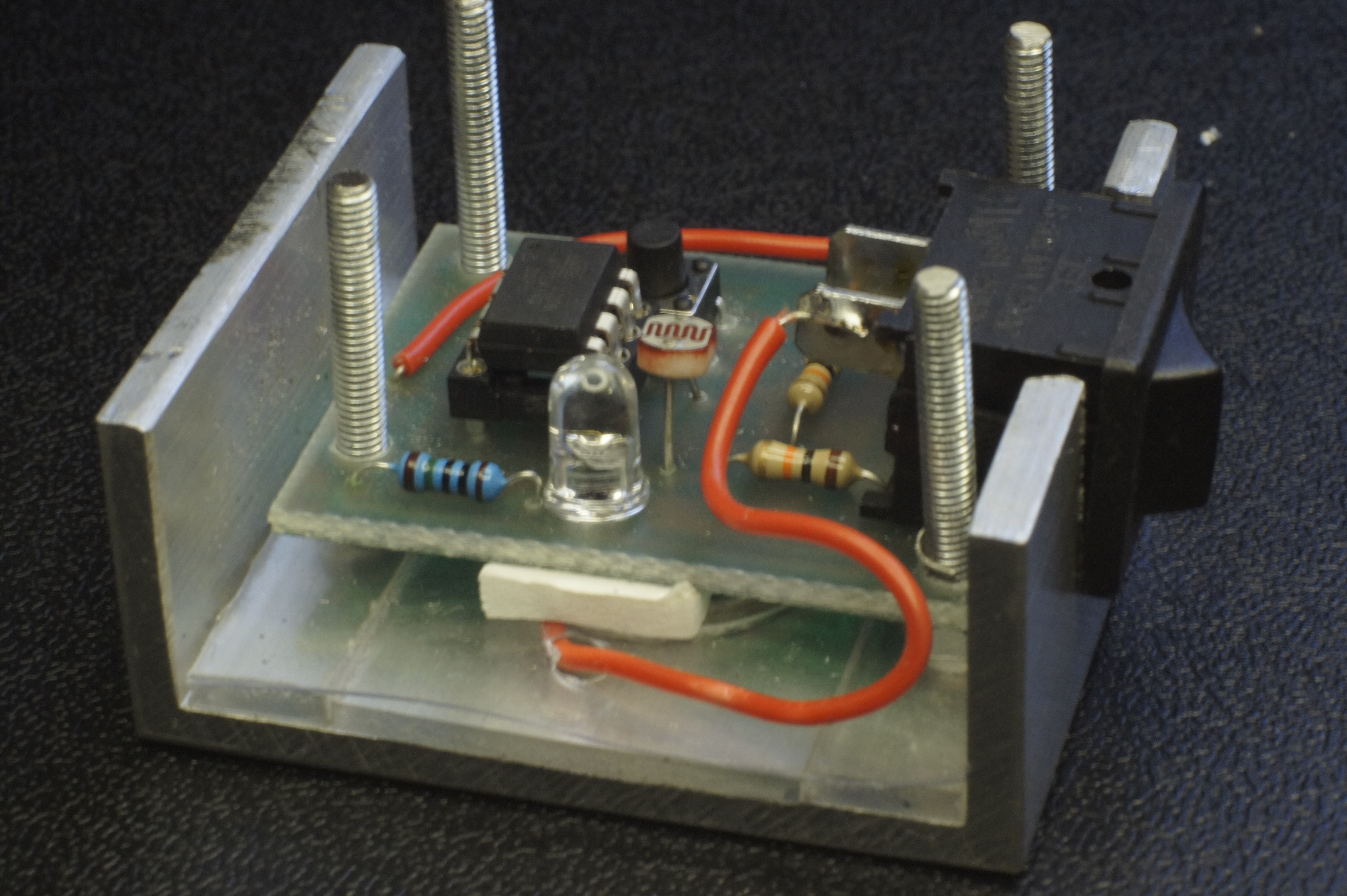
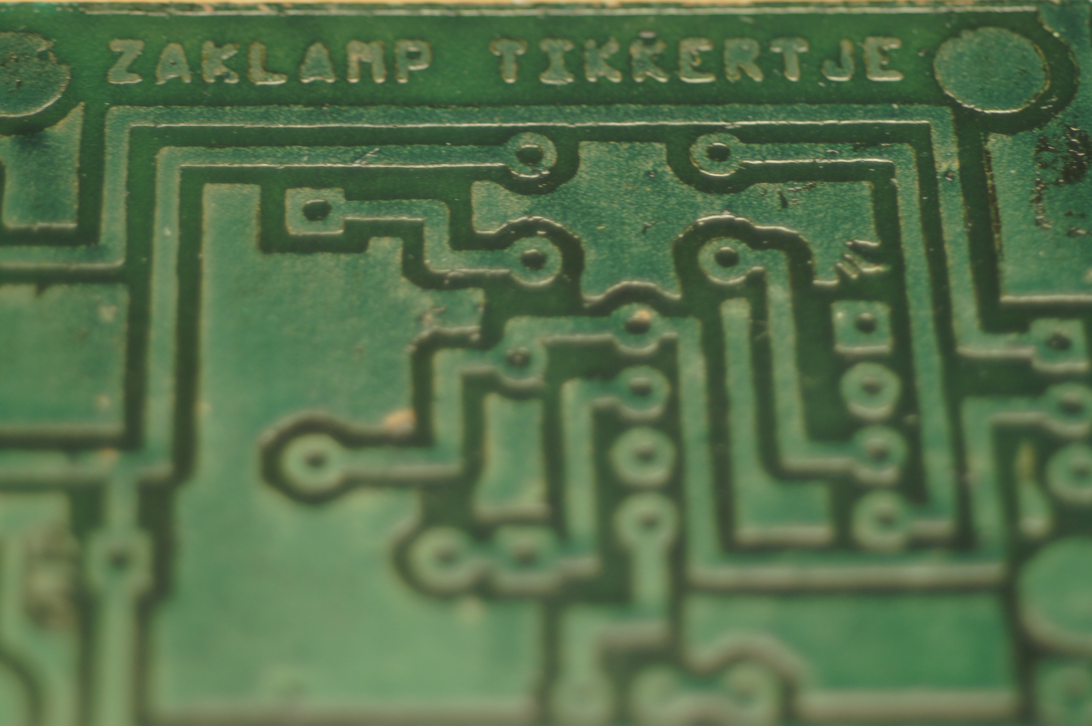
You probably know the game of flashlight-tag. You just run around in the dark on a campsite. You hold your flashlight and try to shine it on one of the other kids, without the other kids shining their lights on you.
I wanted to make this game electronic. The Arduino is my first choice, but would be a bit expensive. I would need one Arduino for each player. The next clip from "Make:" gave me the idea of using a cheap ATtiny:
I want the thing to register a "hit" and show this for a couple of seconds and count the number of "hits". That is all it has to do.
What Do You Need
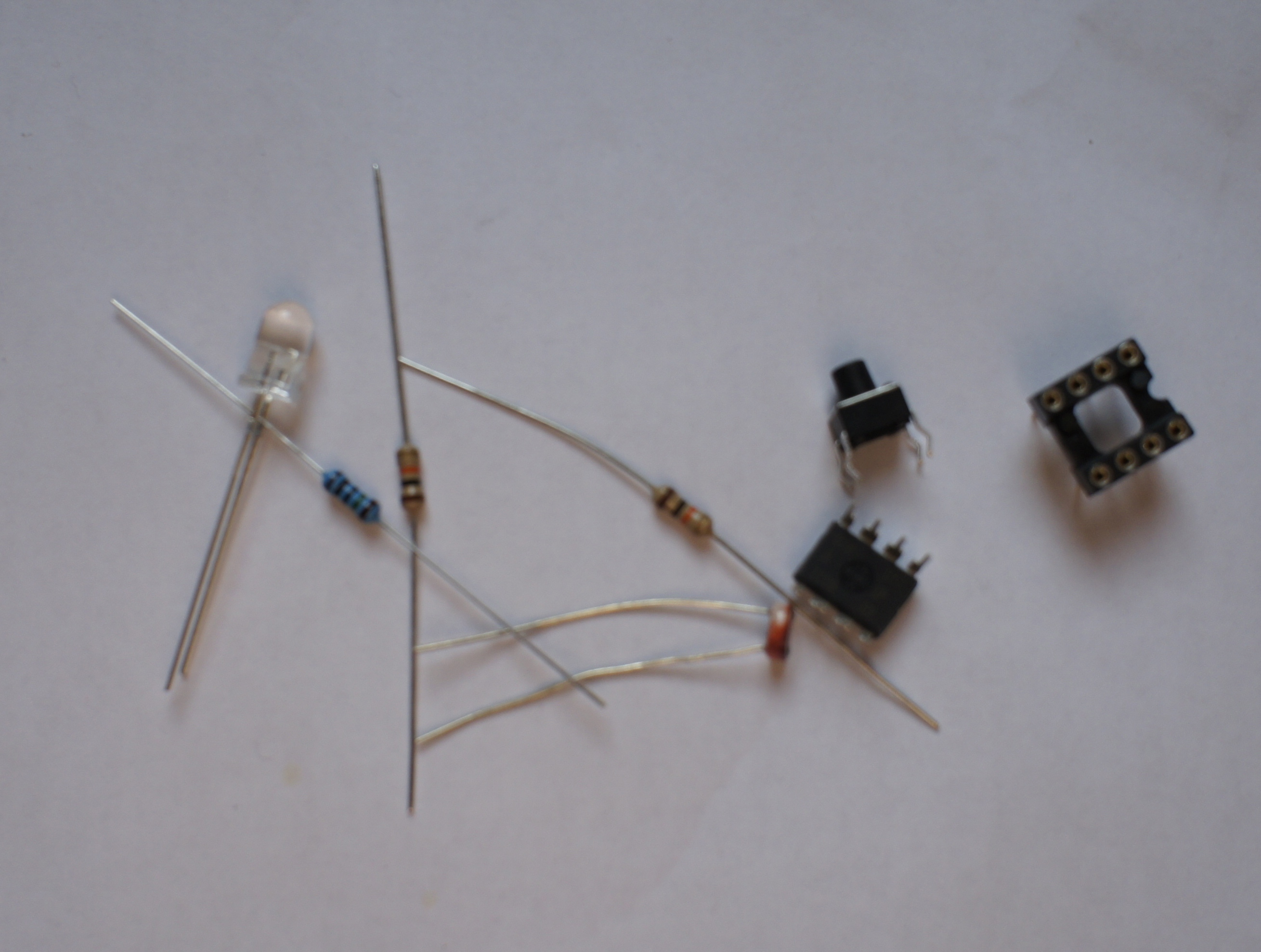
You will need for the PCB:
To make the PCB:
- 1 ATtiny45
- 1 LED
- 1 resistor to go with the LED
- 2 10 K resistors
- 1 pushbutton
- 1 switch
- 1 light sensitive resistor
- 1 battery (3V button-cell)
To make the PCB:
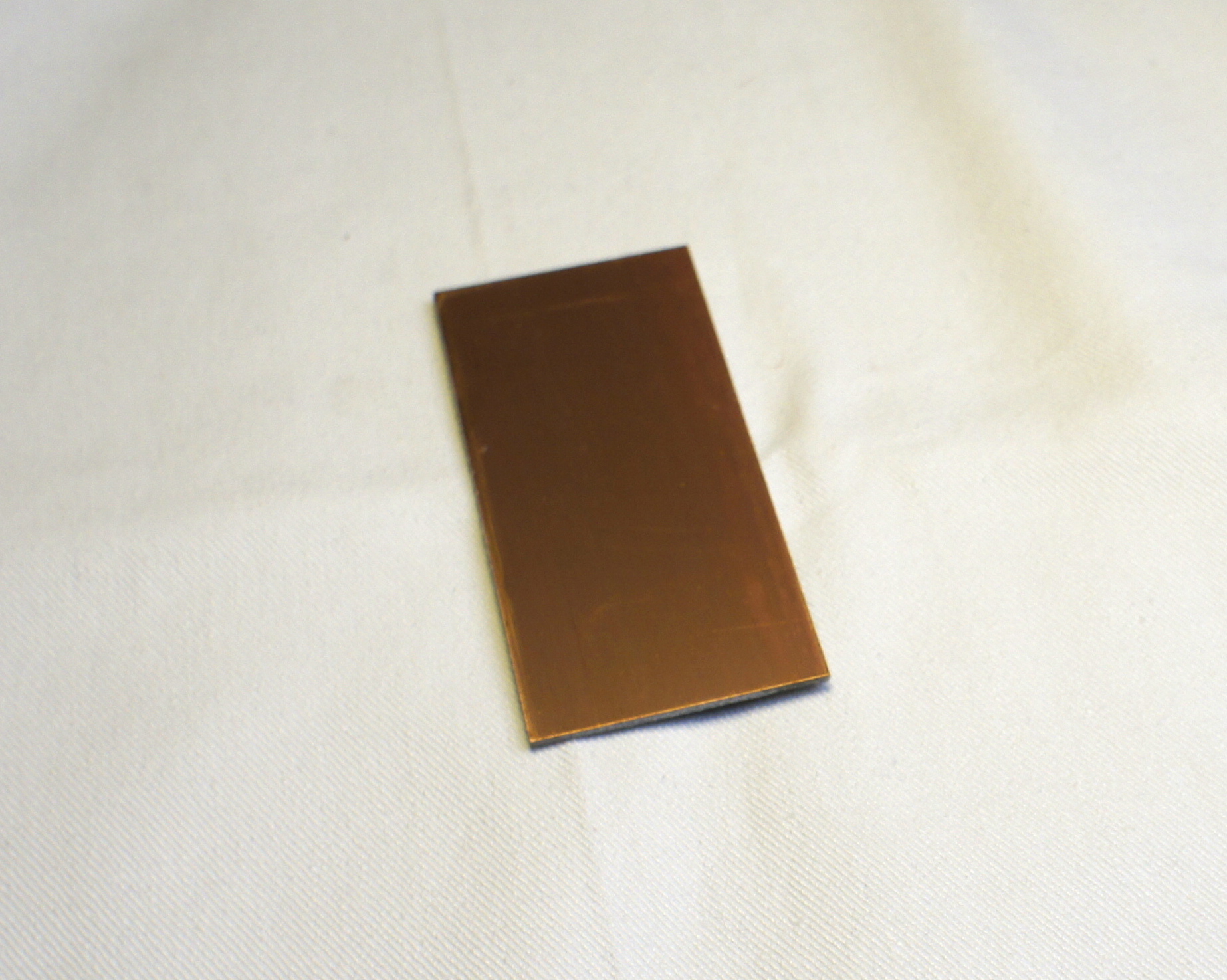
- 1 blank PCB
- Etching solution
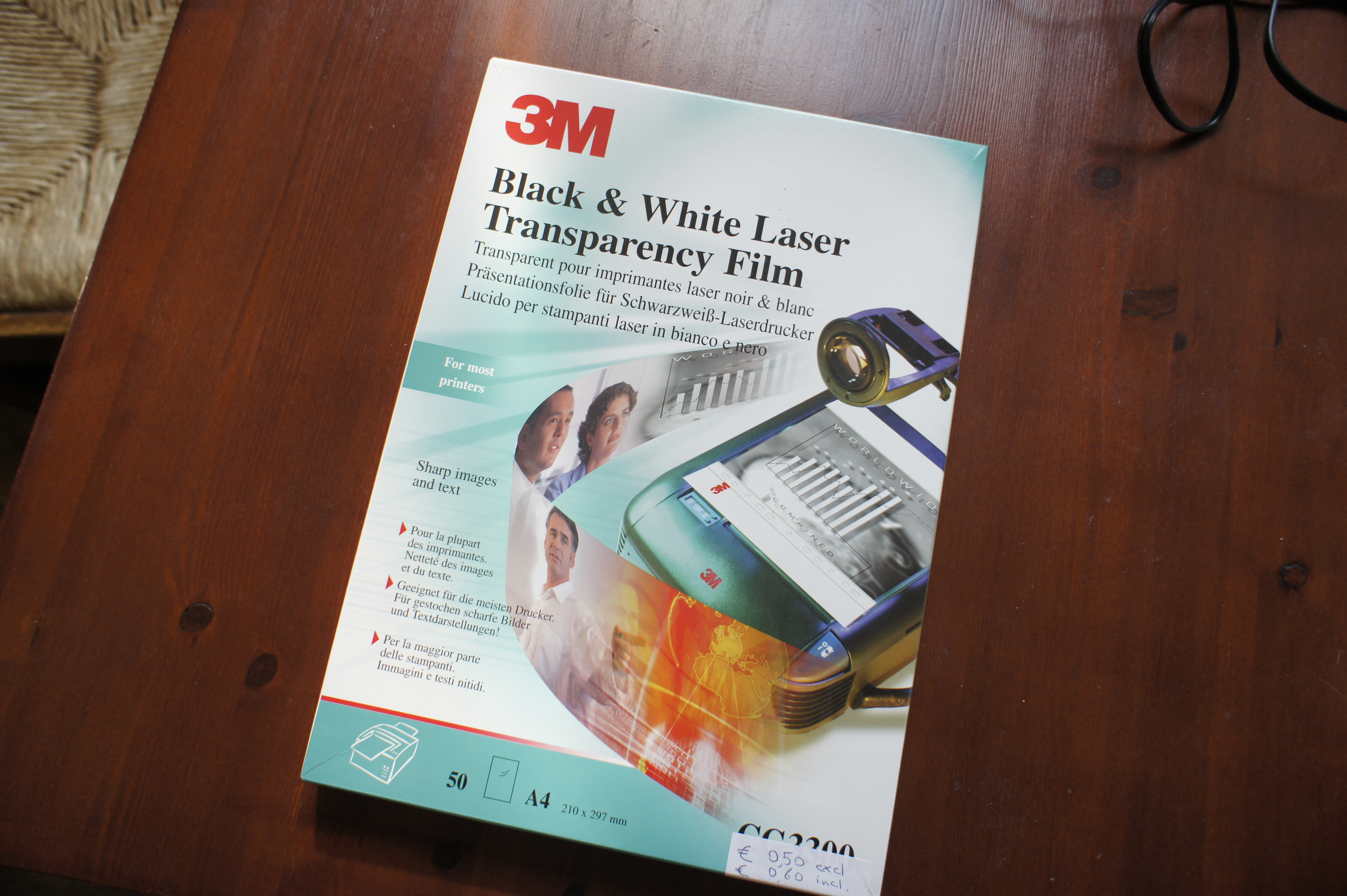
- overhead-foil
- degreaser
- solvant
- sharpy
To make the housing:
- aluminum
- clear acrylic material
- nuts and bolts
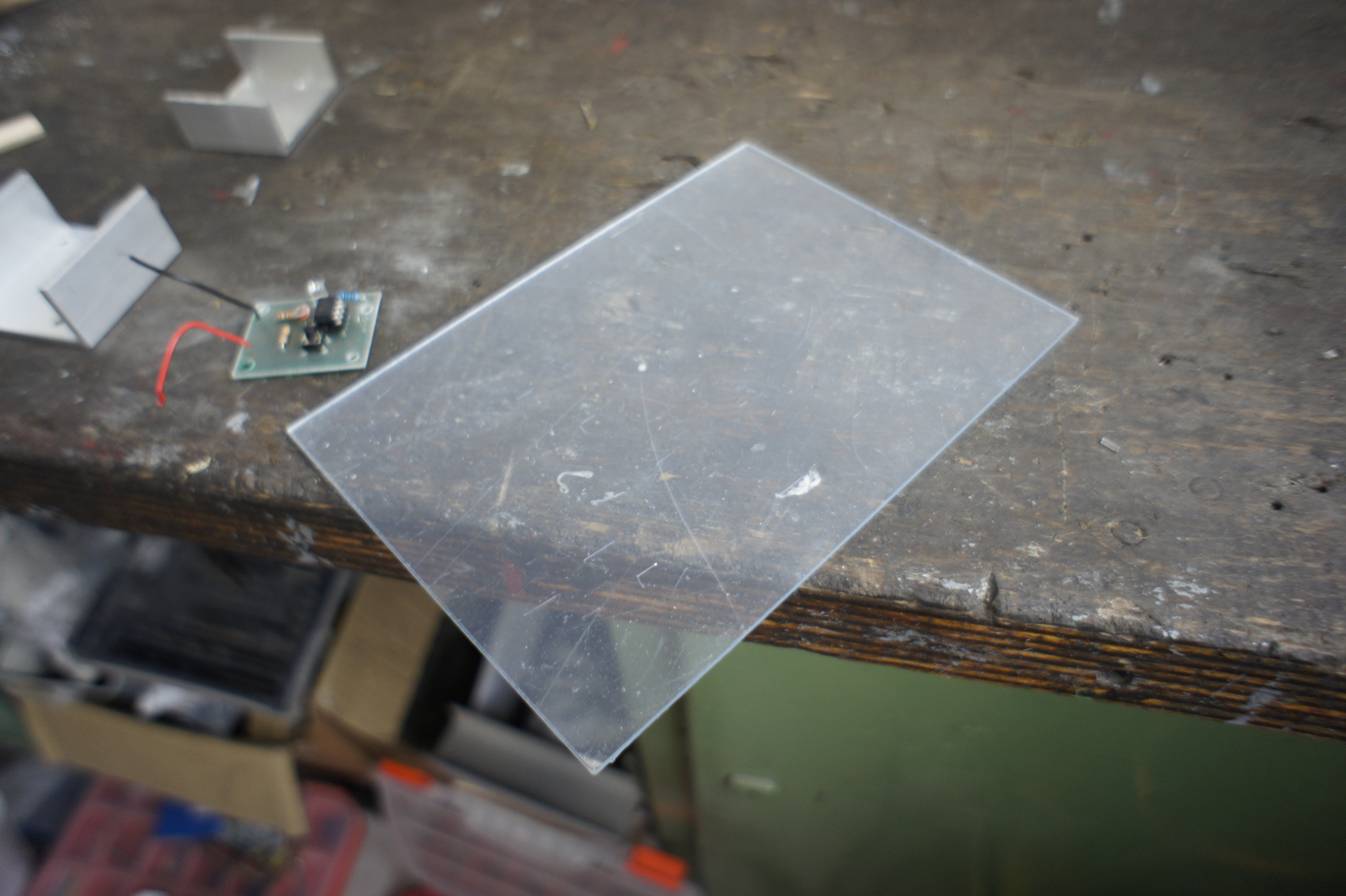
- sheet of plastic
Tools:
- Computer with
- Arduino software
- Fritzing software
- attiny45_85.zip file
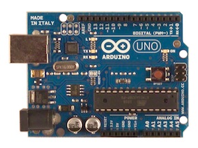
- Arduino board
- breadboard
- jumping-wires
- 10 uF capacitor
- laserprinter
- drill (0,8 - 1 mm)
- drill 3 mm
- drill 20 mm
- soldering tools
- Iron (you know the thing to iron your clothes)
- super-glue
-
foam-tape
Wire Up the Breadboard
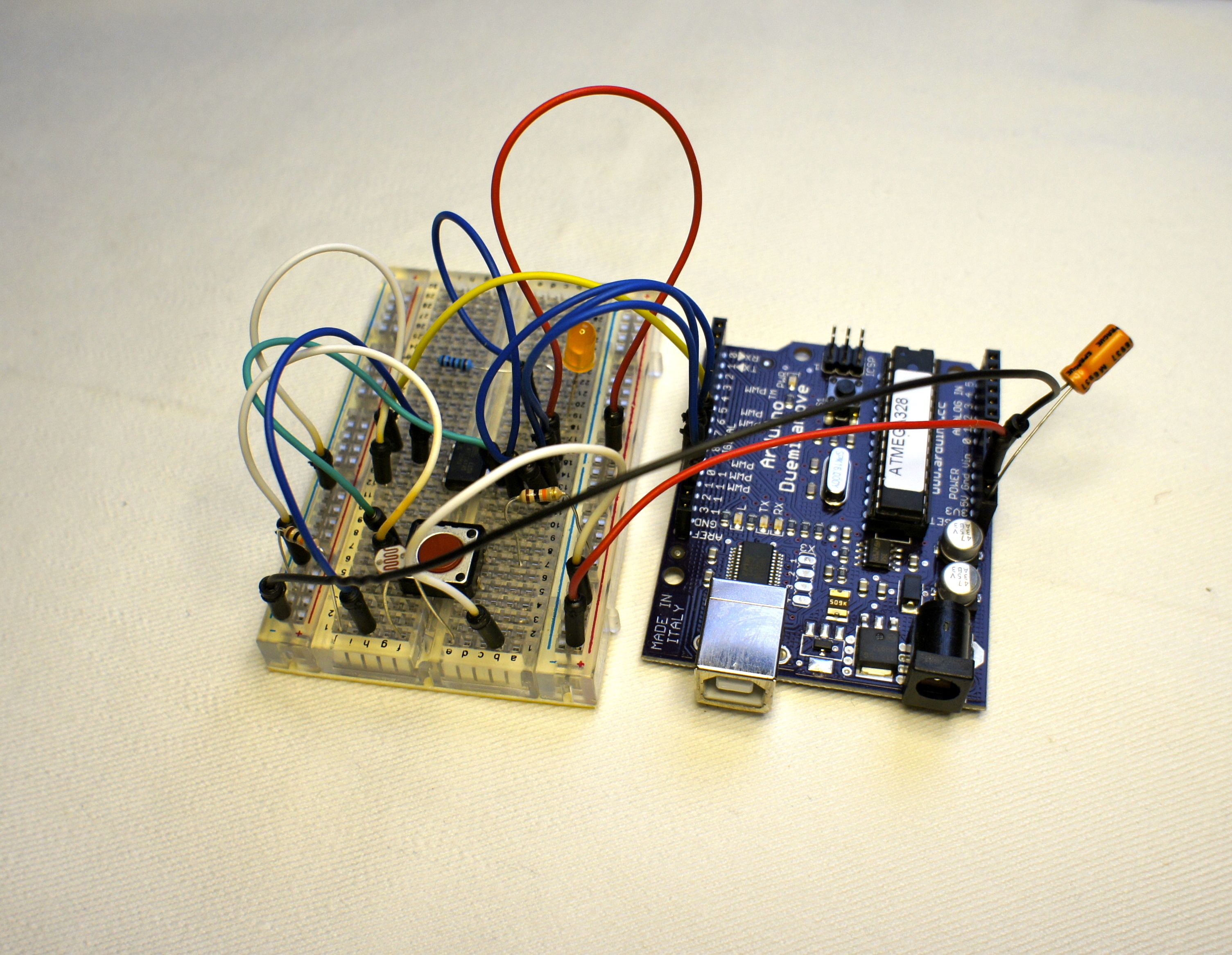
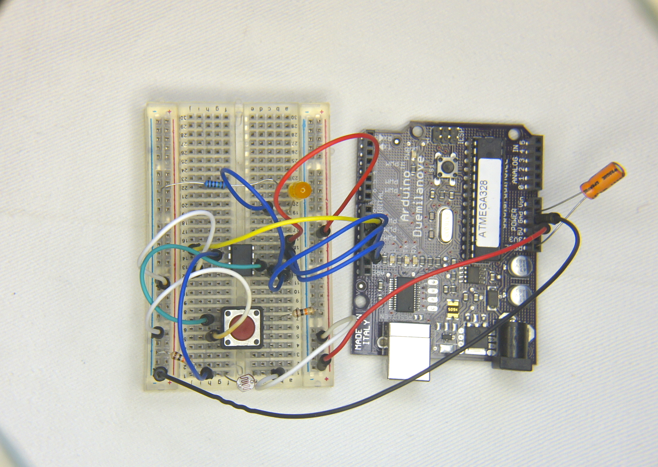
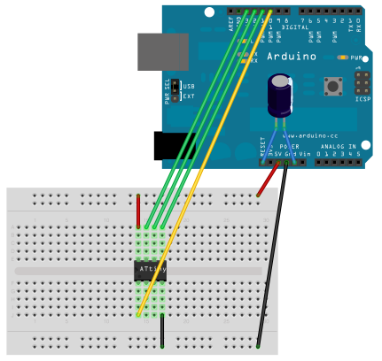
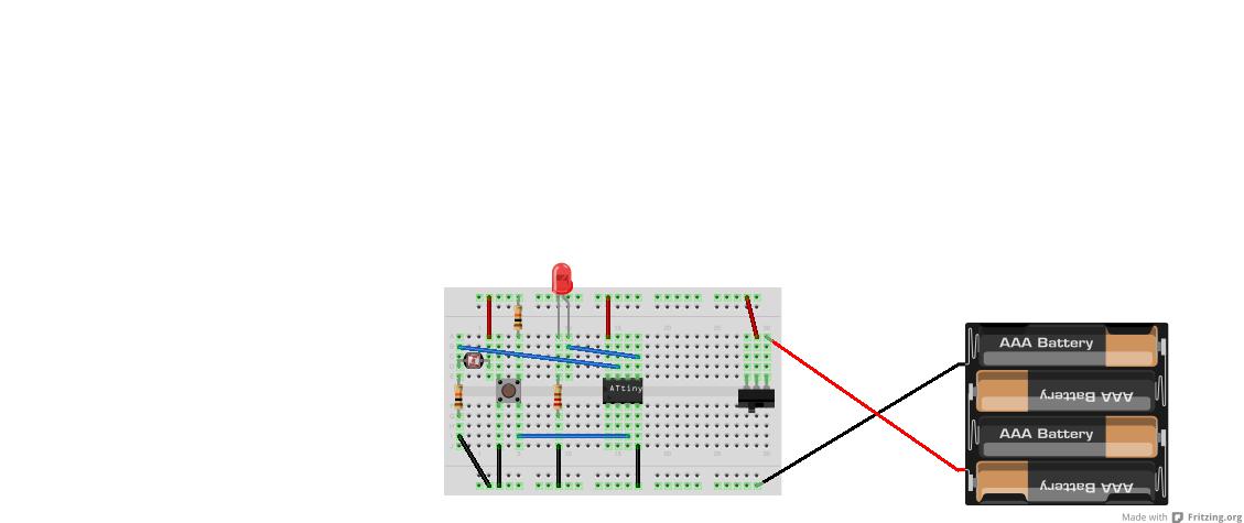

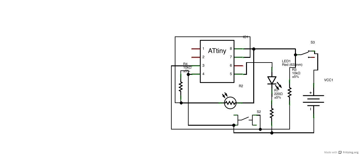
To make the unit that the players will wear, we first design it on a breadboard.
First we put the ATtiny in the breadboard. To program the chip, we need to wire it up to the Arduino. (Look at the drawings to see the numbers of the pins on the ATtiny)
If you want, you can also wire up the rest of the parts, but you don't have to.
I added the Fritzing file for you to check out how to wire up the breadboard.
First we put the ATtiny in the breadboard. To program the chip, we need to wire it up to the Arduino. (Look at the drawings to see the numbers of the pins on the ATtiny)
- Pin 1 (This Pin is marked with a point on the ATtiny) goes to Pin 10 on the Arduino.
- Pin 4 goes to GND (ground)
- Pin 5 goes to Pin 11 on the Arduino
- Pin 6 goes to Pin 12 on the Arduino
- Pin 7 goes to Pin 13 on the Arduino
- Pin 8 goes to +5V
- Next we need to put the 10uF capacitor between the Reset-pin and the GND on the Arduino. (The line on the capacitor shows the wire that should go in the GND. Do not mix this up: capacitors can blow up if you turn it around)
If you want, you can also wire up the rest of the parts, but you don't have to.
I added the Fritzing file for you to check out how to wire up the breadboard.
Downloads
Uploading the Software
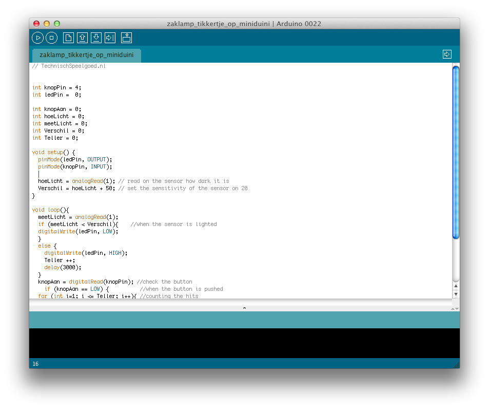
To upload the program to the ATtiny, we need to use the Arduino. The Arduino needs to run the special software from MIT. (http://hlt.media.mit.edu/?p=1229)
Installing the ATtiny support:
If you get an other error, just try again that just might work.
If you did the complete electronics on your breadboard in the previous step, it should work now. This means that if you turn off the lights, than put power on your breadboard, the LED will blink when you shine a light on the sensor. If you push the button, the LED will flash as many times as the sensor was lighted.
The SKETCH (code)
Installing the ATtiny support:
- Download: attiny45_85.zip
- Locate your Arduino sketchbook folder (you can find its location in the preferences dialog in the Arduino software)
- Create a new sub-folder called “hardware” in the sketchbook folder.
- Copy the attiny45_85 folder from the attiny45_85.zip to the hardware folder.
- Restart the Arduino development environment.
- Run the Arduino development environment.
- Open the ArduinoISP sketch from the examples menu.
- Select the board and serial port that correspond to your Arduino board.
- Upload the ArduinoISP sketch.
- Select “ATtiny45 (w/ Arduino as ISP)” or “ATtiny85 (w/ Arduino as ISP)” from the Tools > Board menu (leave the serial port set to that of your Arduino board).
- Upload the sketch.
avrdude: please define PAGEL and BS2 signals in the configuration file for part ATtiny85
avrdude: please define PAGEL and BS2 signals in the configuration file for part ATtiny85
If you get an other error, just try again that just might work.
If you did the complete electronics on your breadboard in the previous step, it should work now. This means that if you turn off the lights, than put power on your breadboard, the LED will blink when you shine a light on the sensor. If you push the button, the LED will flash as many times as the sensor was lighted.
The SKETCH (code)
int knopPin = 4;
int ledPin =  0;

int knopAan = 0;
int hoeLicht = 0;
int Verschil = 0;
int Teller = 0;

void setup() {
  pinMode(ledPin, OUTPUT);
  pinMode(knopPin, INPUT);

  hoeLicht = analogRead(1); // read on the sensor how dark it is
  Verschil = hoeLicht + 50; // set the sensitivity of the sensor on 50
}

void loop(){
  hoeLicht = analogRead(1);
  if (hoeLicht < Verschil){    //when the sensor is lighted
  digitalWrite(ledPin, LOW);
  }
  else {
    digitalWrite(ledPin, HIGH);
    Teller ++;
    if (Teller > 100){Teller = 99;}
    delay(3000);
    digitalWrite(ledPin, LOW);
    delay(100);
  }
  knopAan = digitalRead(knopPin); //check the button
    if (knopAan == LOW) {          //when the button is pushed
    delay(600); //wait till your finger is from the button
  for (int i=1; i <= Teller; i++){ //counting the hits
  digitalWrite(ledPin, HIGH);
  delay(400);
  digitalWrite(ledPin, LOW);
  delay(400);
  }
    }
}
Downloads
Designing the PCB

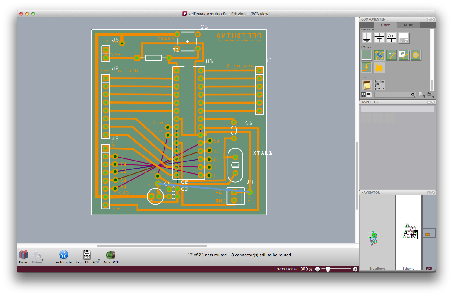
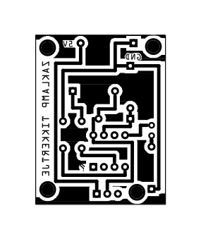

The design software
To design the PCB, I use Fritzing: It is open source and it fits the Arduino way of life.
Check out: www.fritzing.org
The design
Designing a PCB in Fritzing is easier than you might think. I won't say that it isn't a challenge, but just try it, it is fun.
First you put all the components in the breadboard in the breadboard-view. You just place them exactly as you did in the real world.
Next you go to the PCB-view and you will see that this view really is a mess. You now arrange the components how you would like them on your PCB. Now you click autoroute and the magic happens. It is never exactly right the first time. Sometimes it just helps to click autoroute again and sometimes you have to move, turn or change some parts. You can also draw your own copper.
(this is not a Fritzing tutorial, there are many on the web)
(I added the actual Fritzing file I made, so you can play with it)
Exporting your design
Now you can export your design. (if you don't want to etch your own PCB, you can also order the PCB directly from the Fritzing program) But I will be etching my own PCB, so I will export it for etching. This will result in a nice PDF-file. Doesn't it look cool.
Printing your design
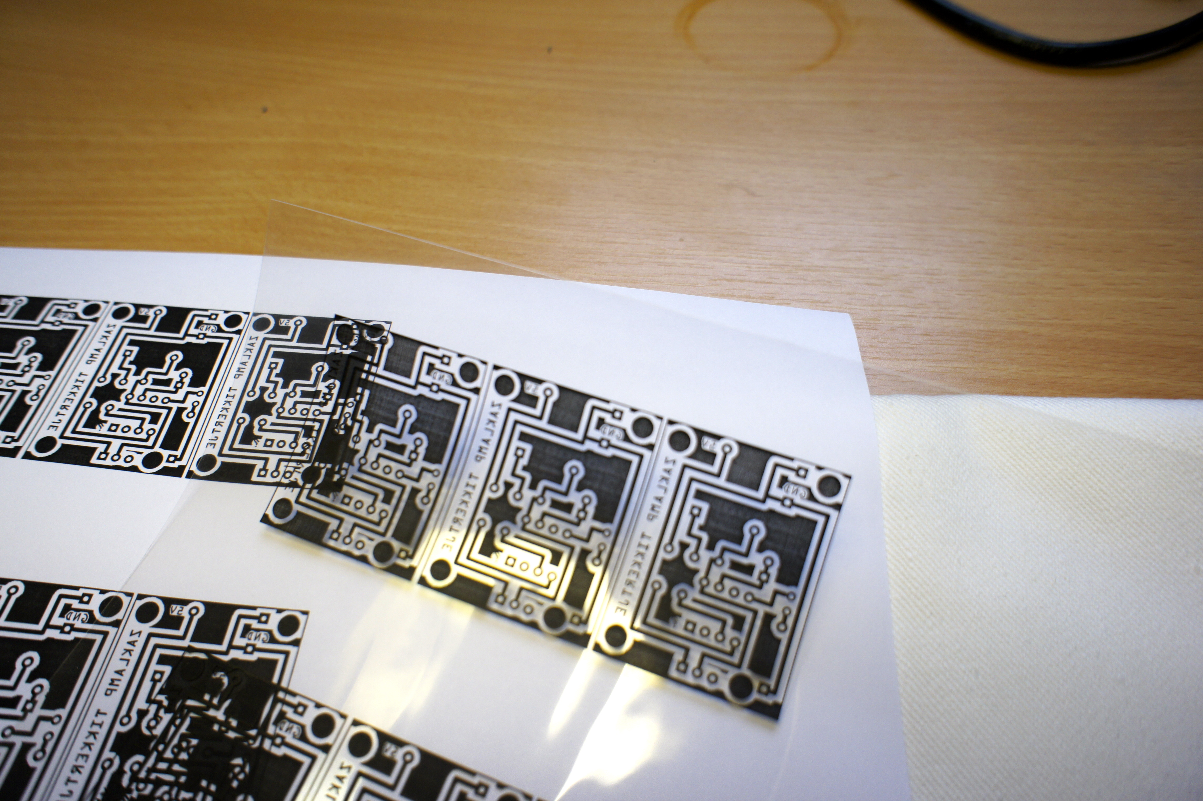
To print your design, you will need a laser-printer. A bubble-jet won't do. First I use a vector-drawing program to put more than one PCB on one sheet of paper. You could use a program like Adobe Illustrator. My legal version of Illustrator doesn't work anymore (since I'm running Lion), so I use Inkscape. This is also a free program. See www.inkscape.org.
Now I first print on a normal sheet of paper and look wether the parts will fit. My printer makes the designs slightly smaller than they should so I have to print my designs 103%. Just check what your printer does.
If the size is right, you can get your 3M transparent sheet en print your design on that.
Making the PCB

Cutting to size
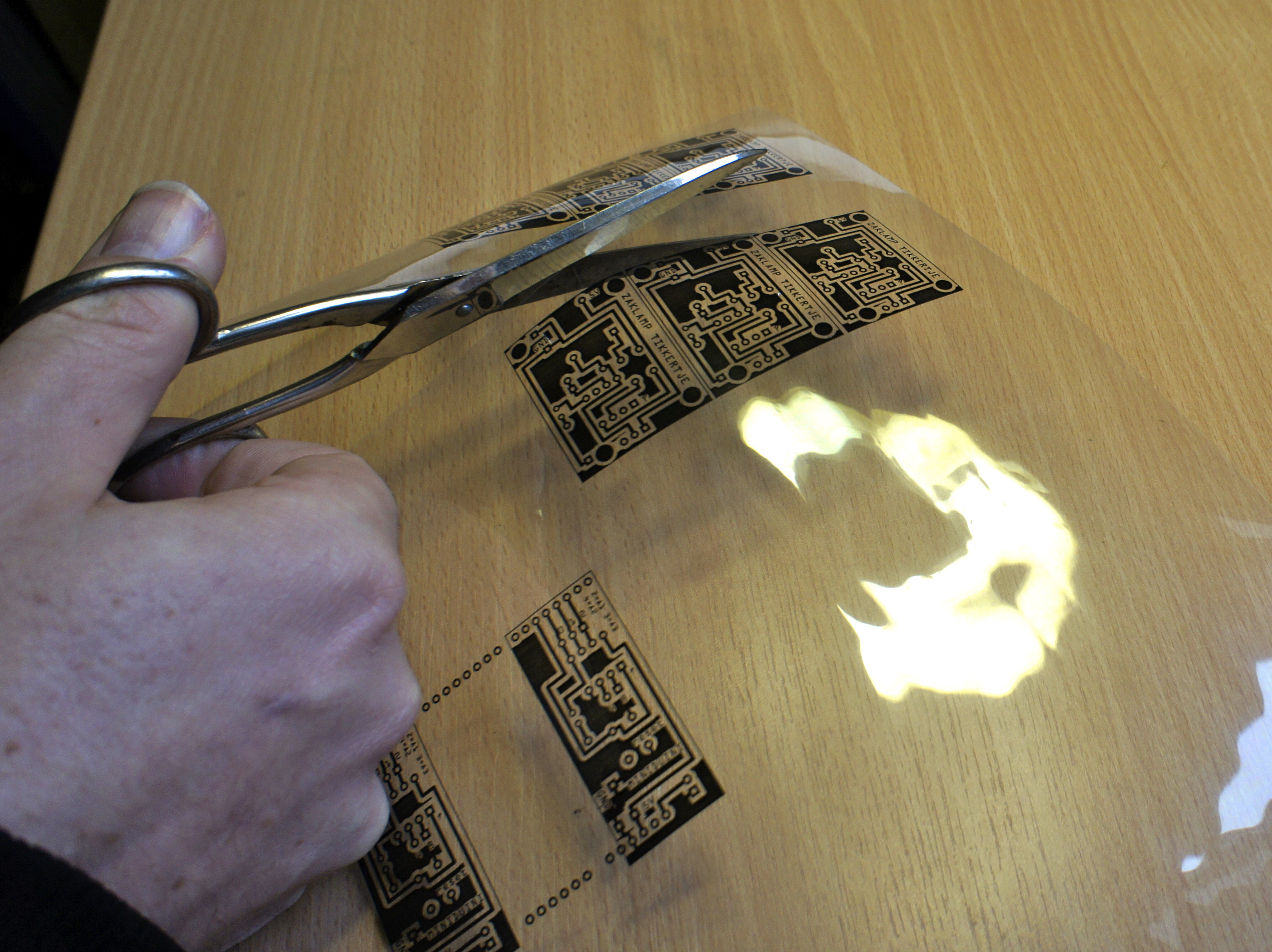
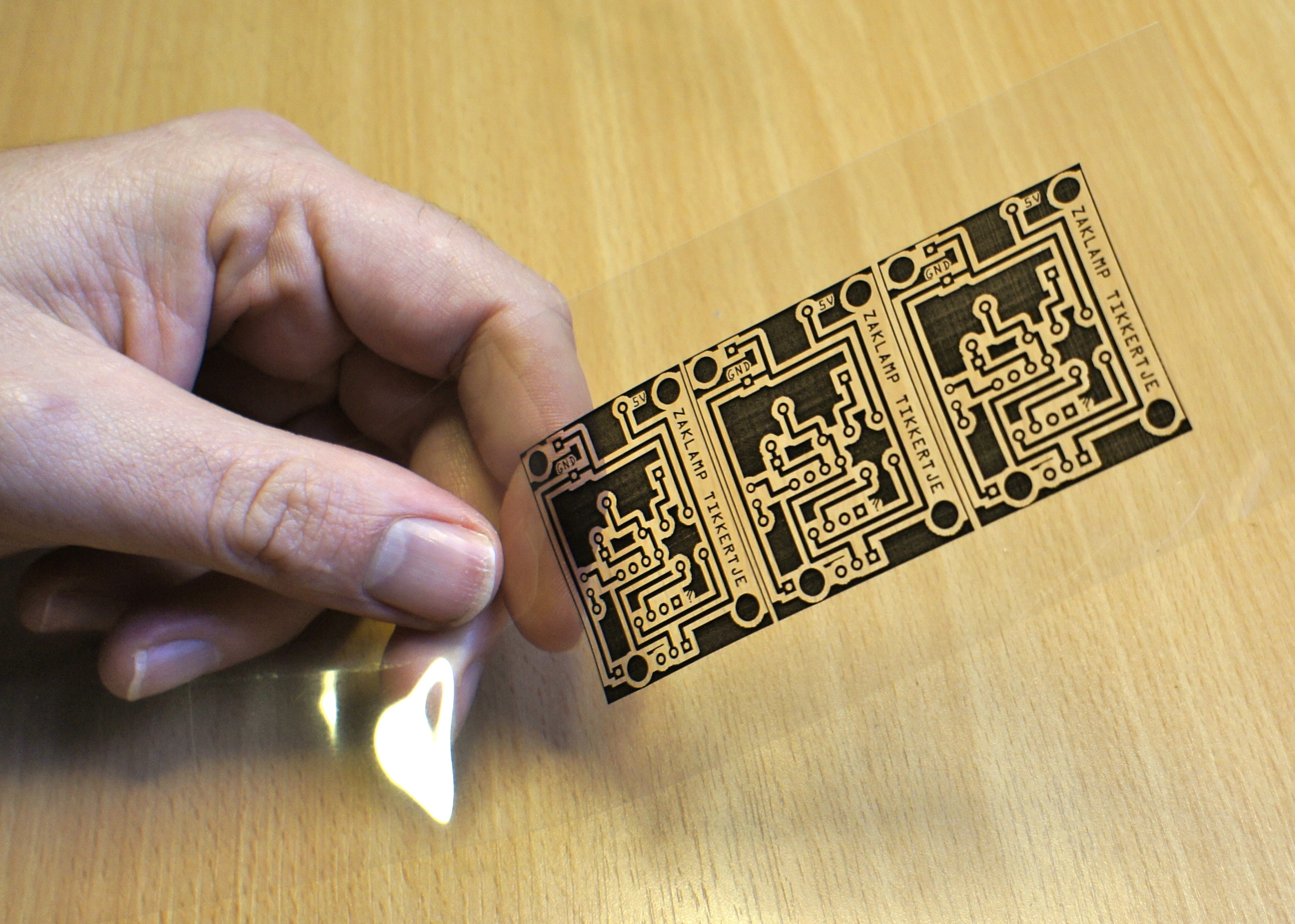
First you cut the PCB you want to make from the printed sheet. Next you'l need to cut some PCB material a little bit bigger than your design. (the trick is to cut with a hobby knife into the copper and than break it on the edge of the table). Before you do anything else, it is wise to check if your design fits your copper. Now it is a good idea to clean the copper side of the PCB material with some kind of solvent. (be smart, wear rubber gloves!)
Transferring the design to the copper
(this method I learned from Make:)
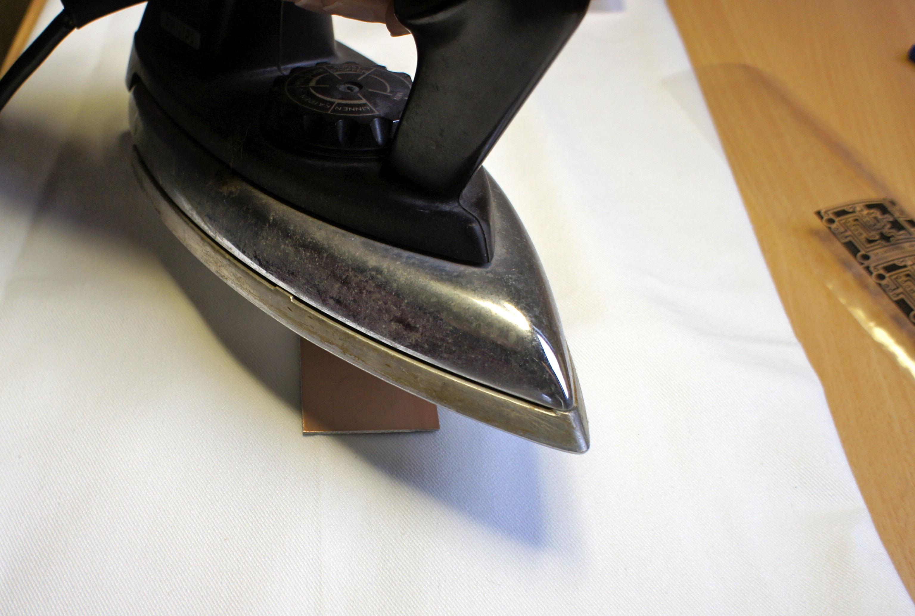
You put your iron as hot as it will get and you heat up the copper by just pressing the iron down on it. (be sure to use a surface than can handle the heat, like a ironing board)
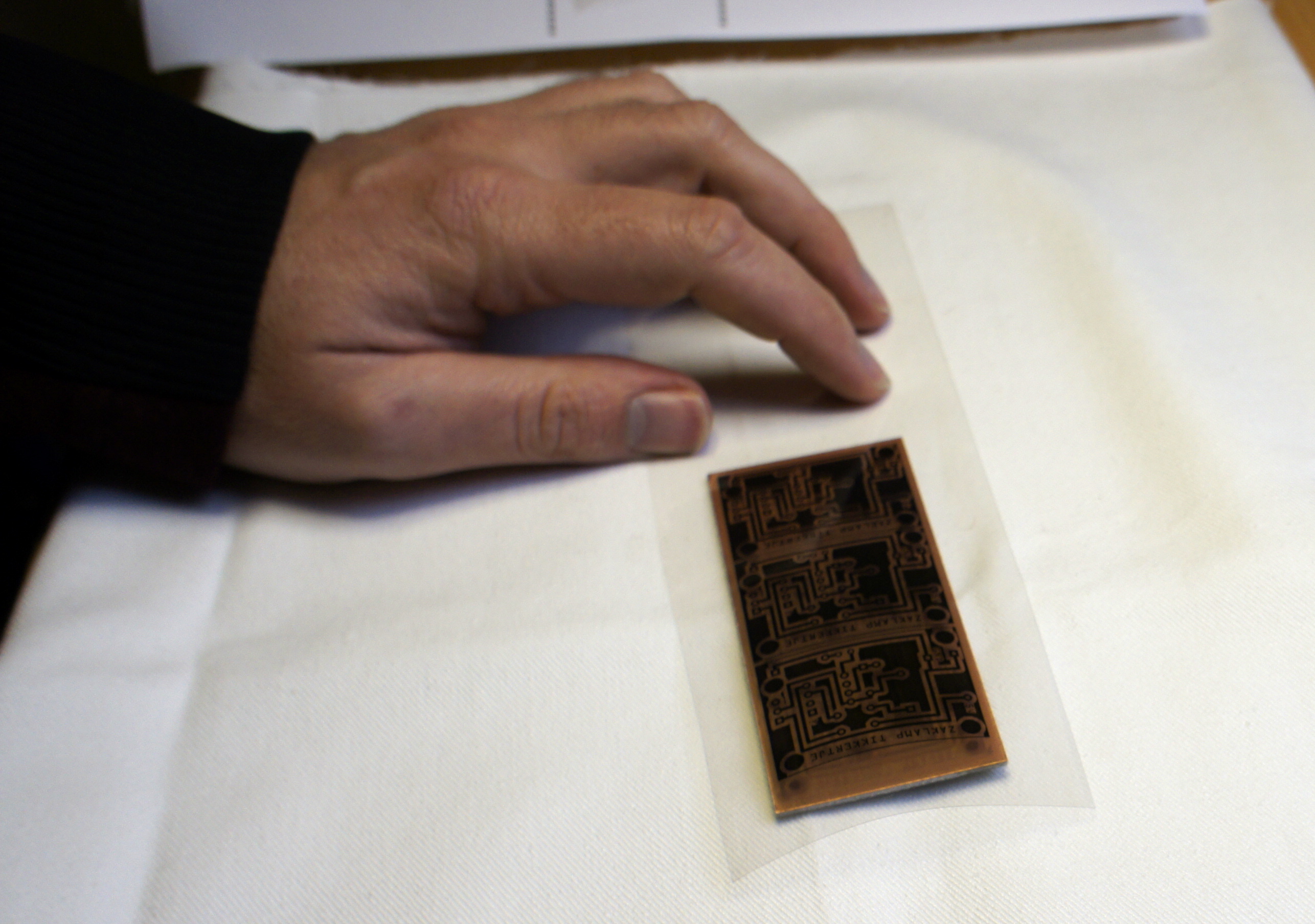
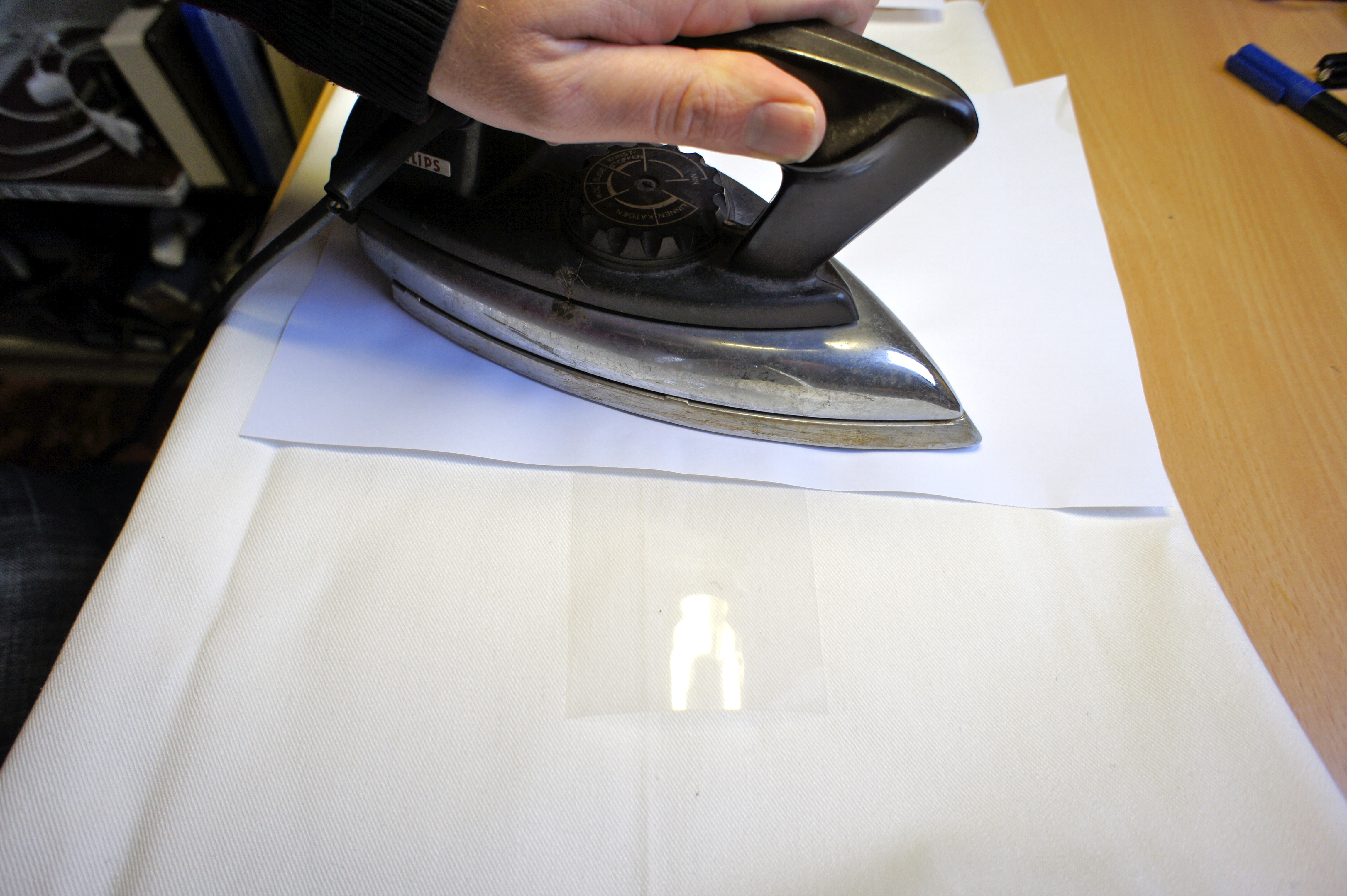
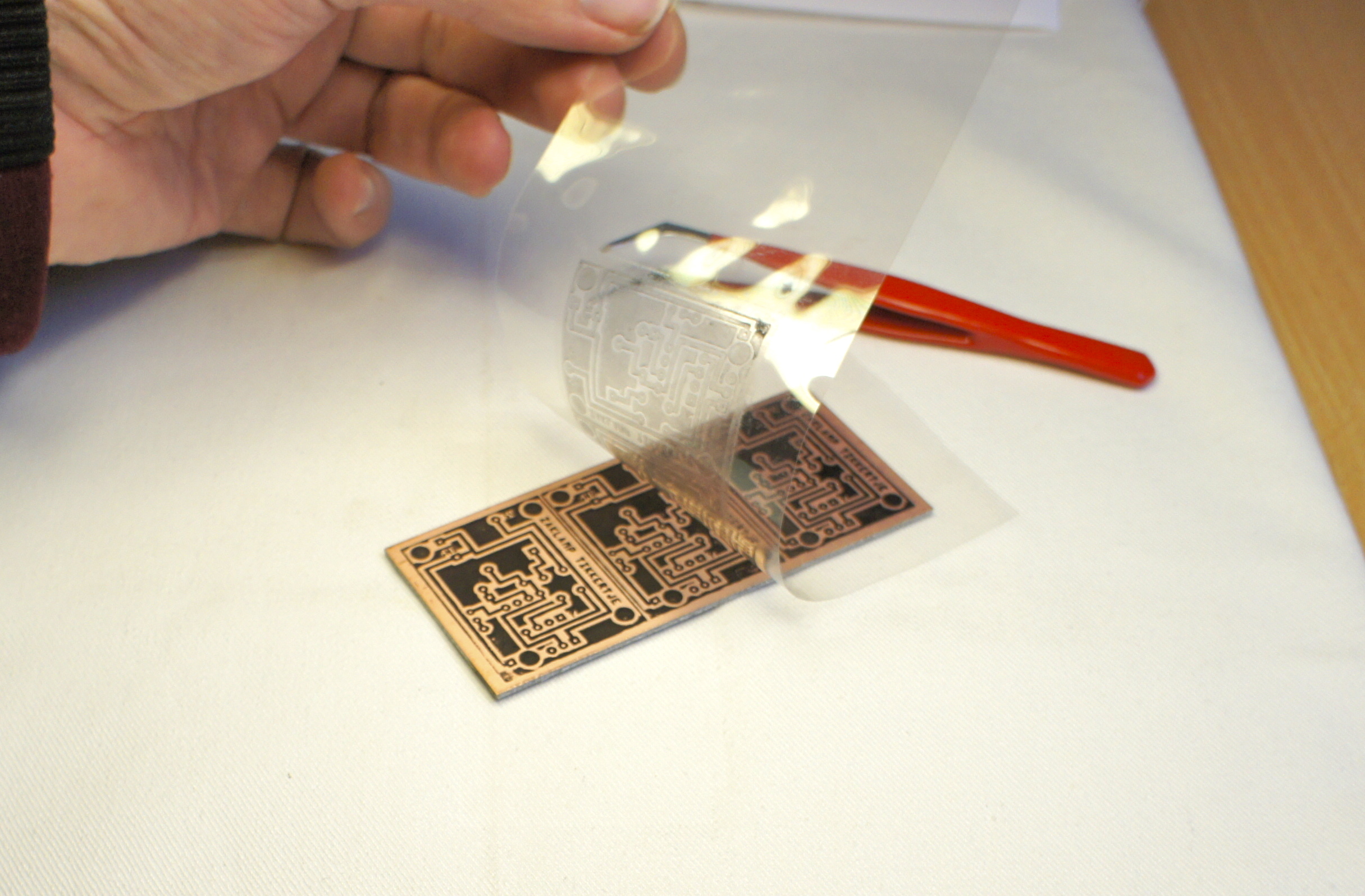
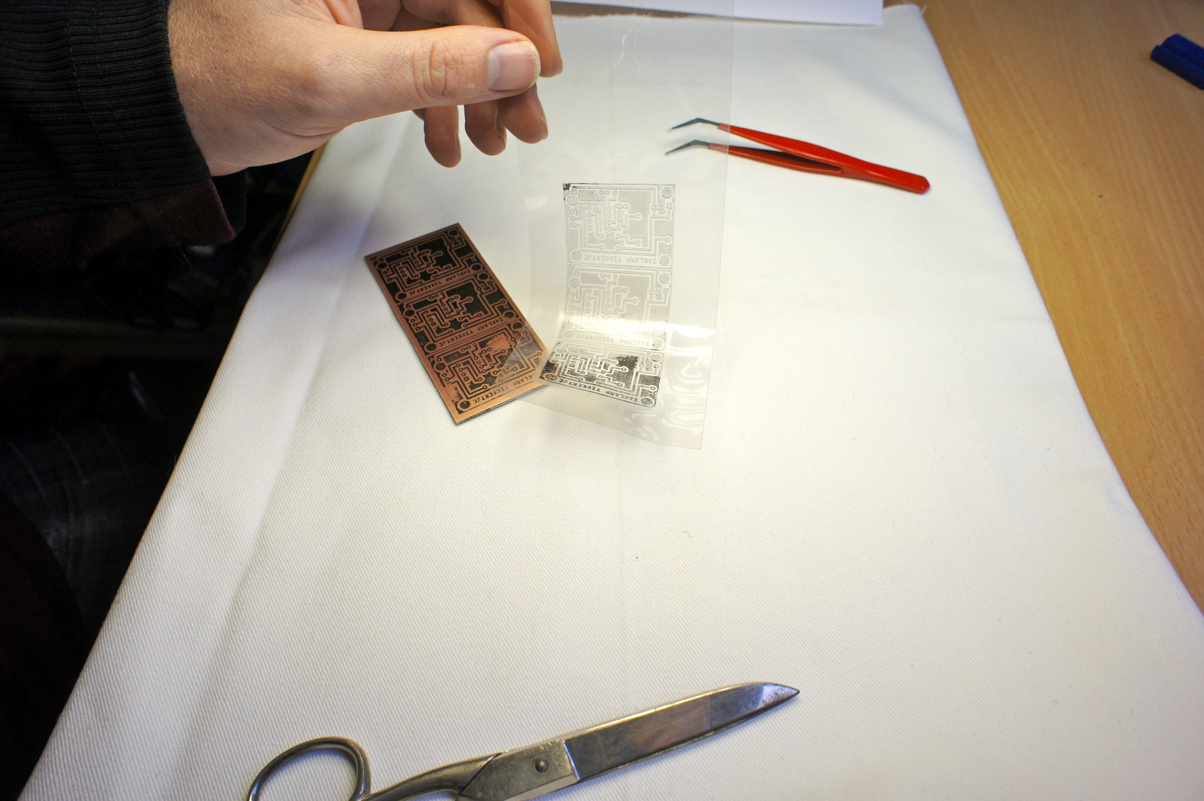
Now comes the hard part: You must place the transparent sheet, with the printed side down on the hot copper. This must go right the first time and you must be very careful not to move it anymore, once it touched the copper. The toner (laser printer-ink) will melt directly on the copper. Now without moving the sheet on the copper, put a sheet of normal, not printed, paper on top of it and iron it again.
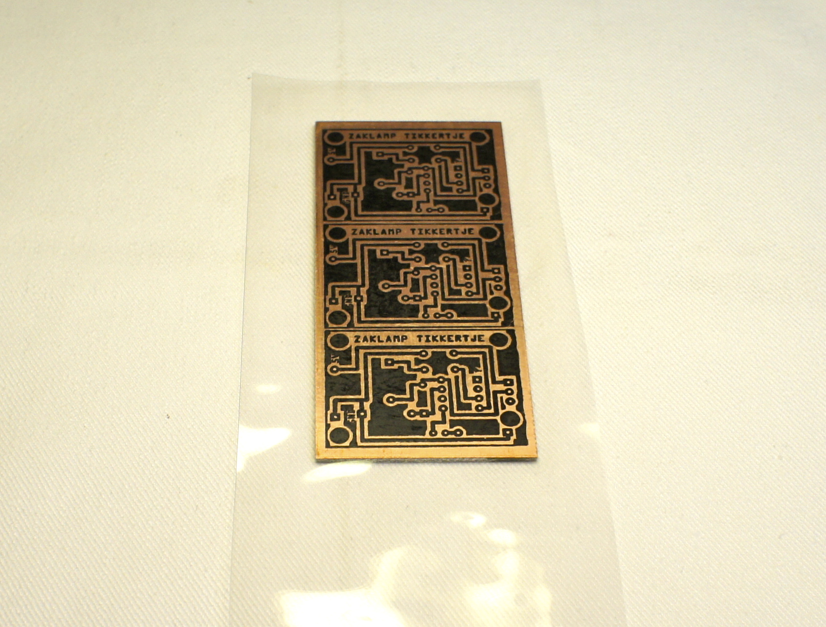
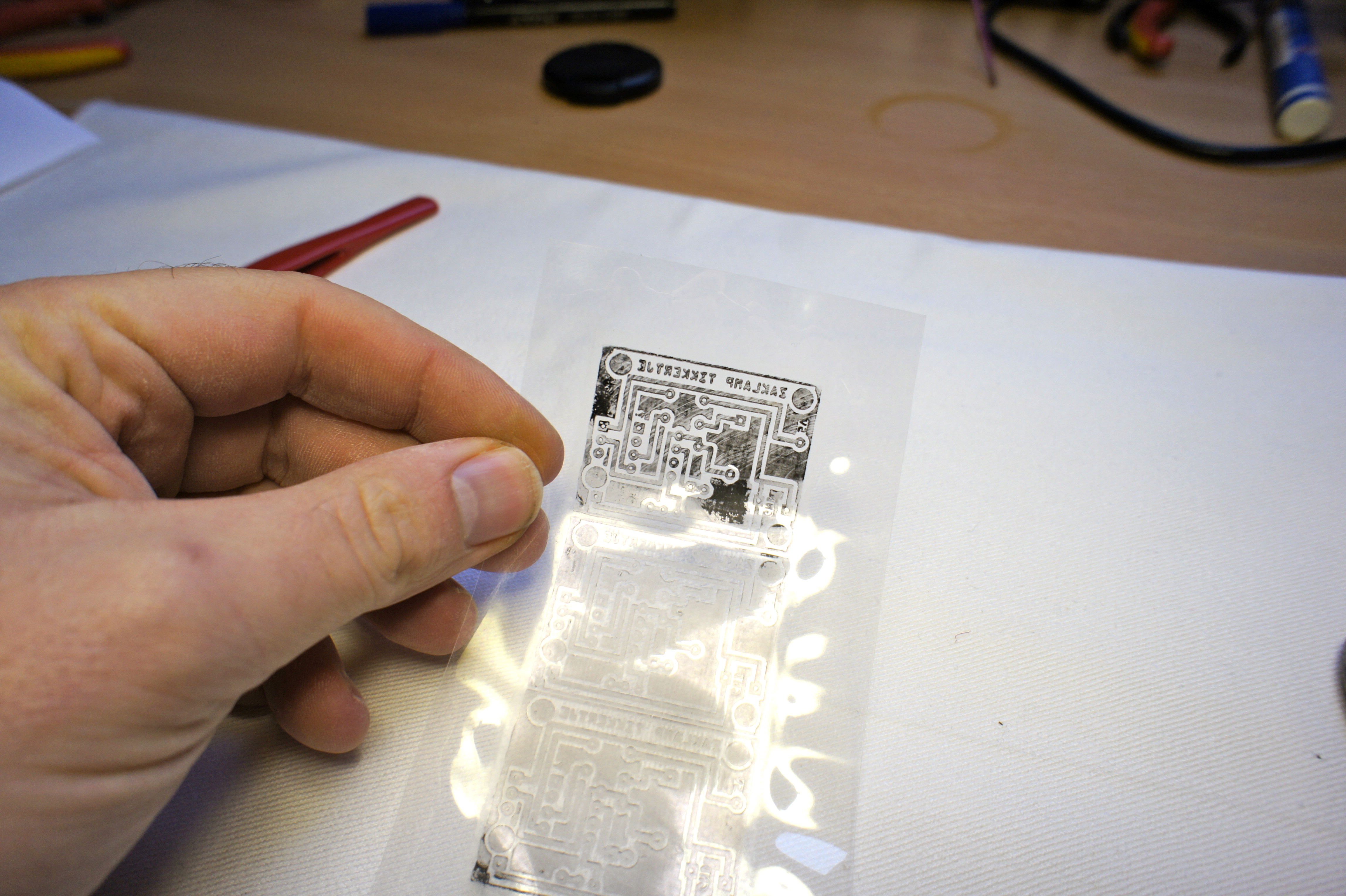
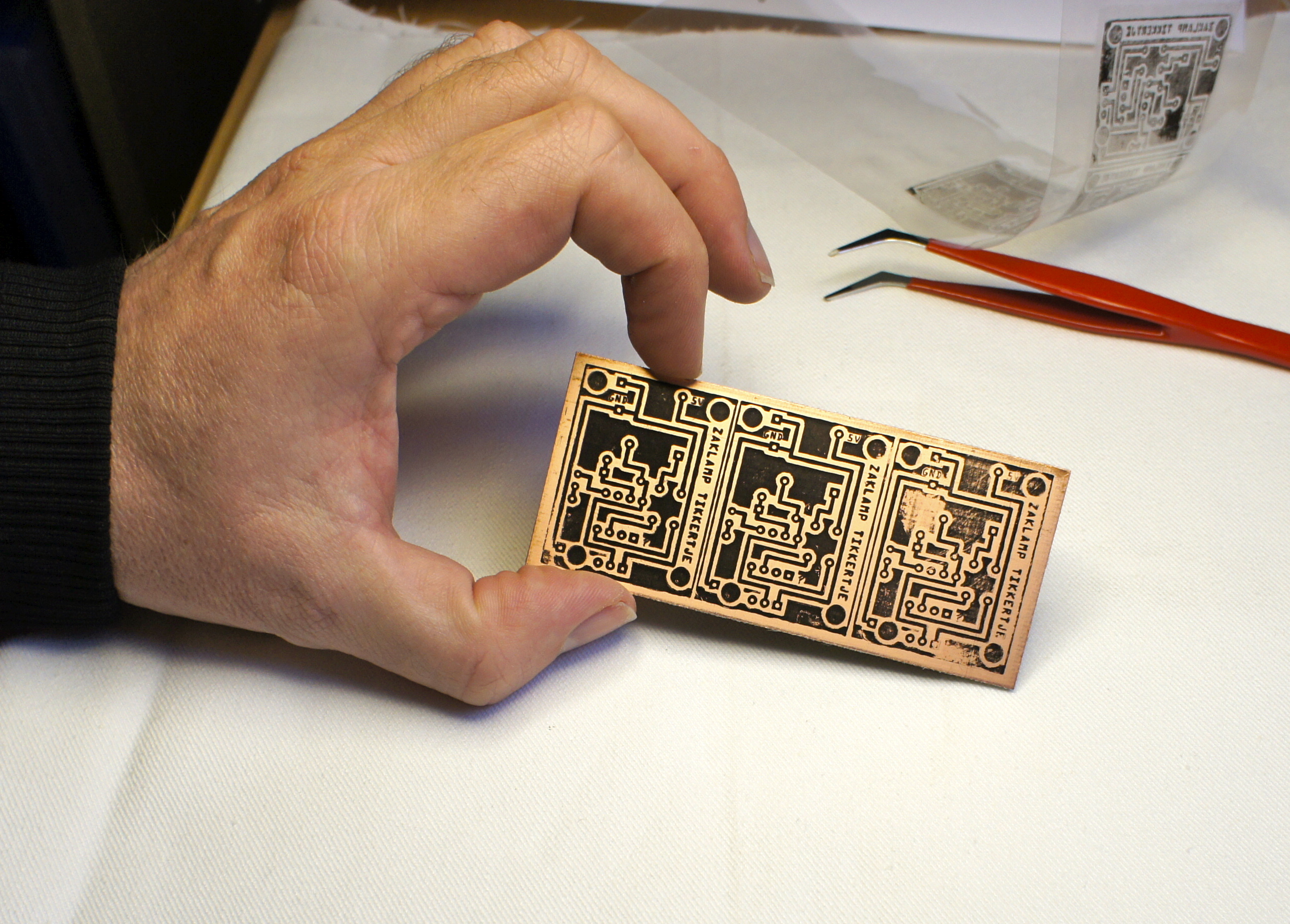
Now carefully remove the transparent sheet from the copper and, if everything went well, your design is on the copper.
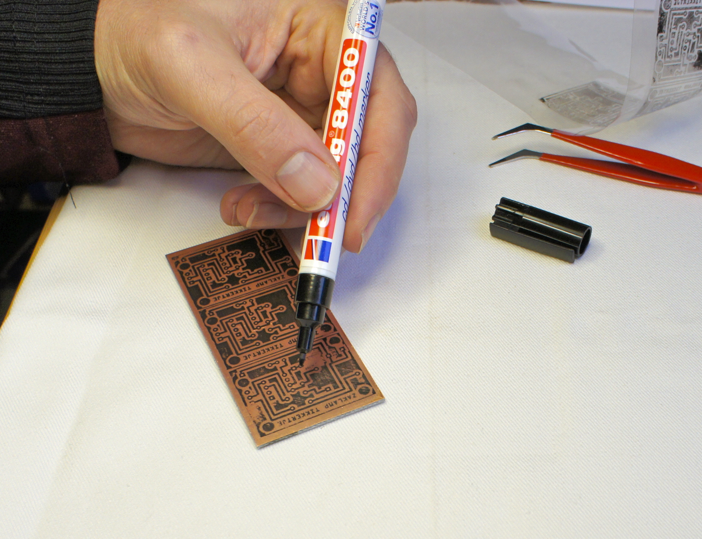
In my case, two of the three PCB's I did went OK, but one wasn't so great. To fix up this handicapped PCB, I took a sharpy and filled in the missing lines.
(be very careful when you remove the sheet from the copper, because the copper is very, very hot by now)
Etching the PCB
Now the real fun starts.
Wear the proper protection and be sure that your workspace is well ventilated and you have plenty of clean water nearby.
Prepare the etching solution according to the instructions of the manufacturer. (this is serious stuff, so don't mess with this)
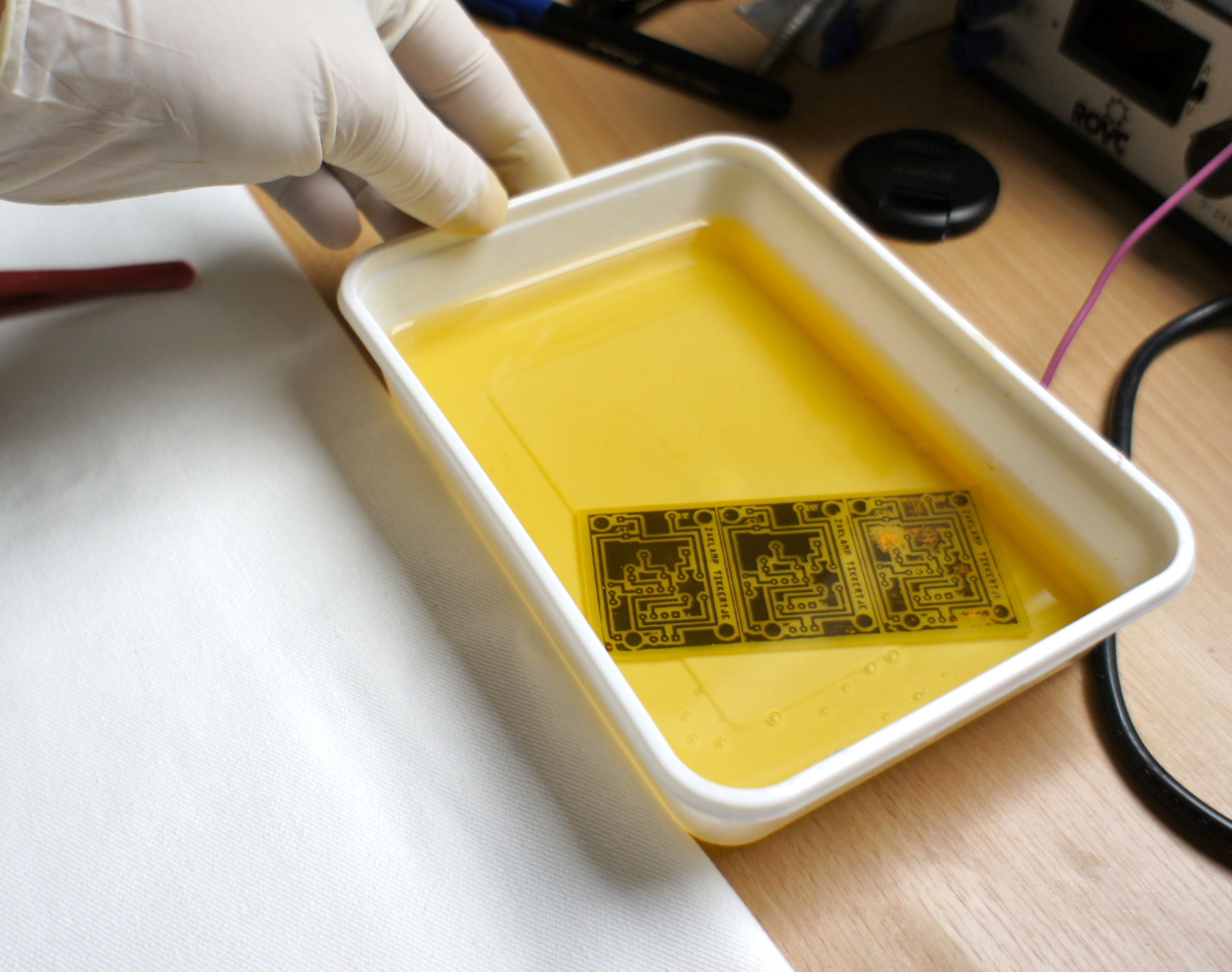
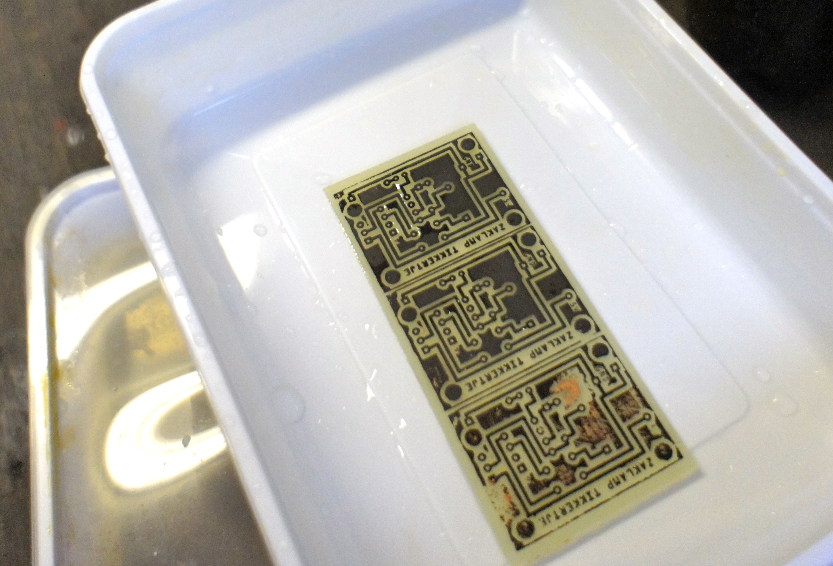
There are different kinds of etching solutions and different methods of etching. I use the brown ferro stuff. (this stuff will stain anything) I noticed that the method in the Make: video washes away the sharpy-lines, so I just let the etching-solution do its work and I just rock the dish a little until I see that all the copper that was visible is etched away. Now I take the PCB out of the solution and wash it with plenty of water.
Finishing the PCB


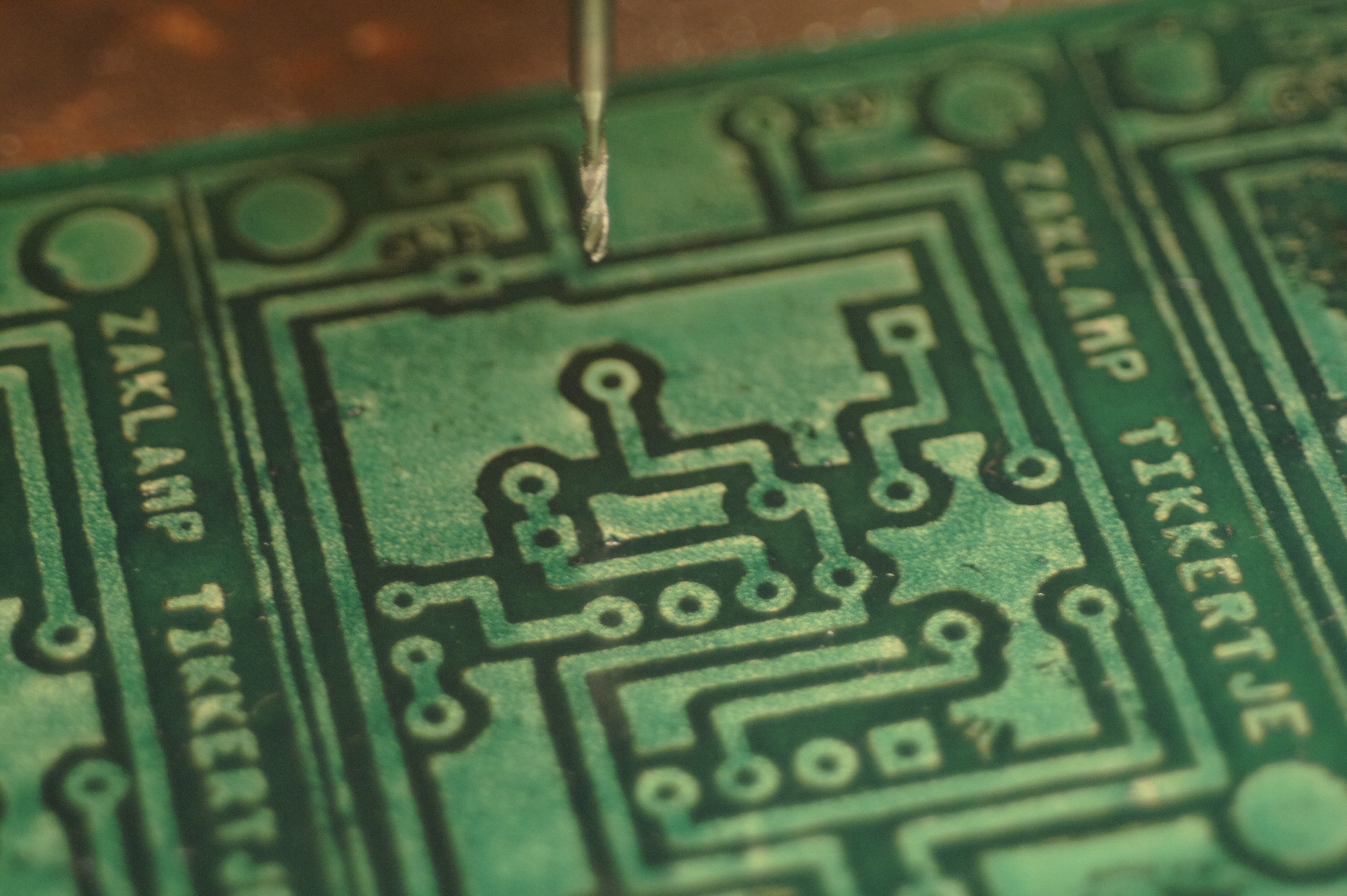
Cleaning off the toner
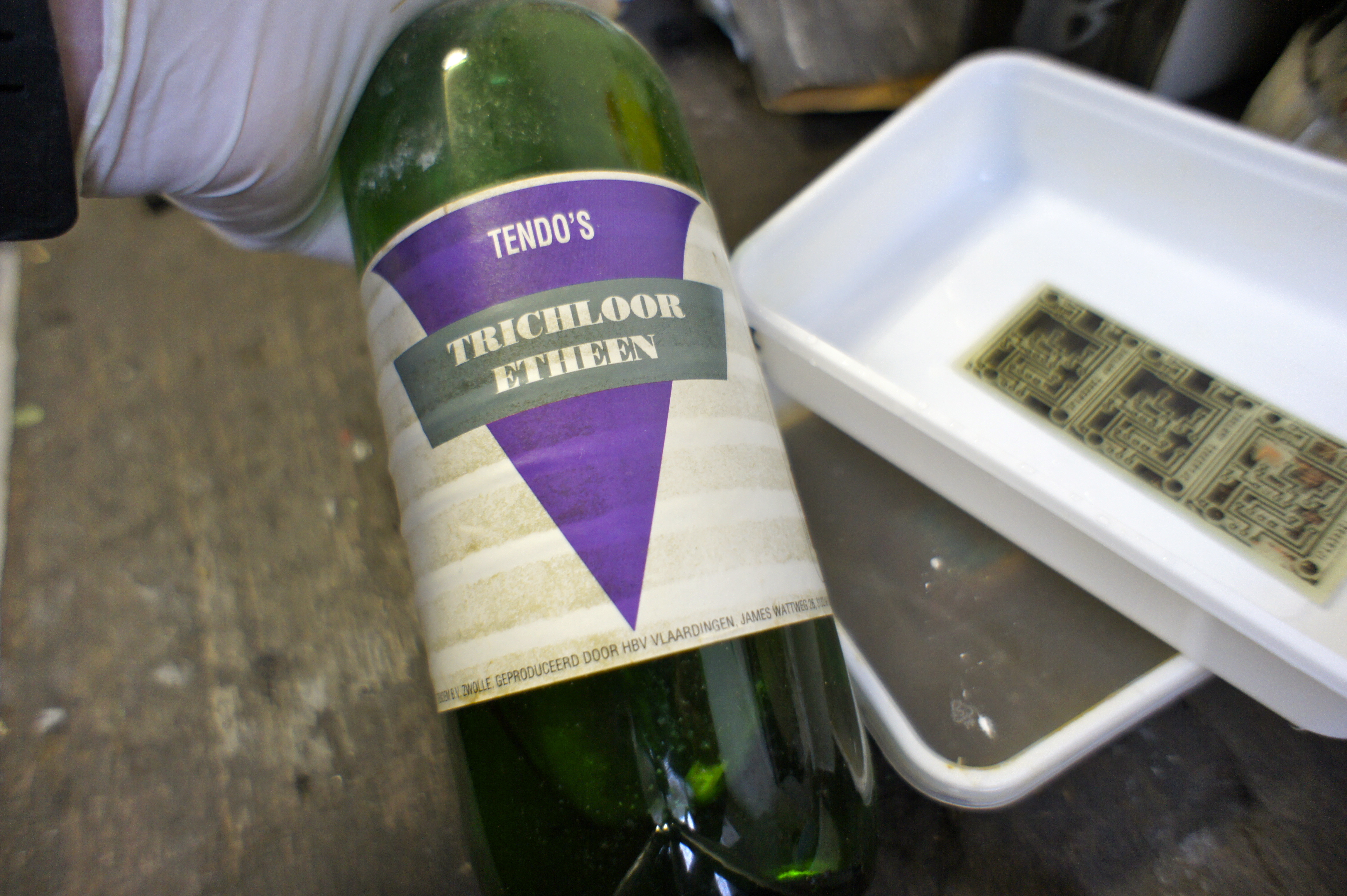
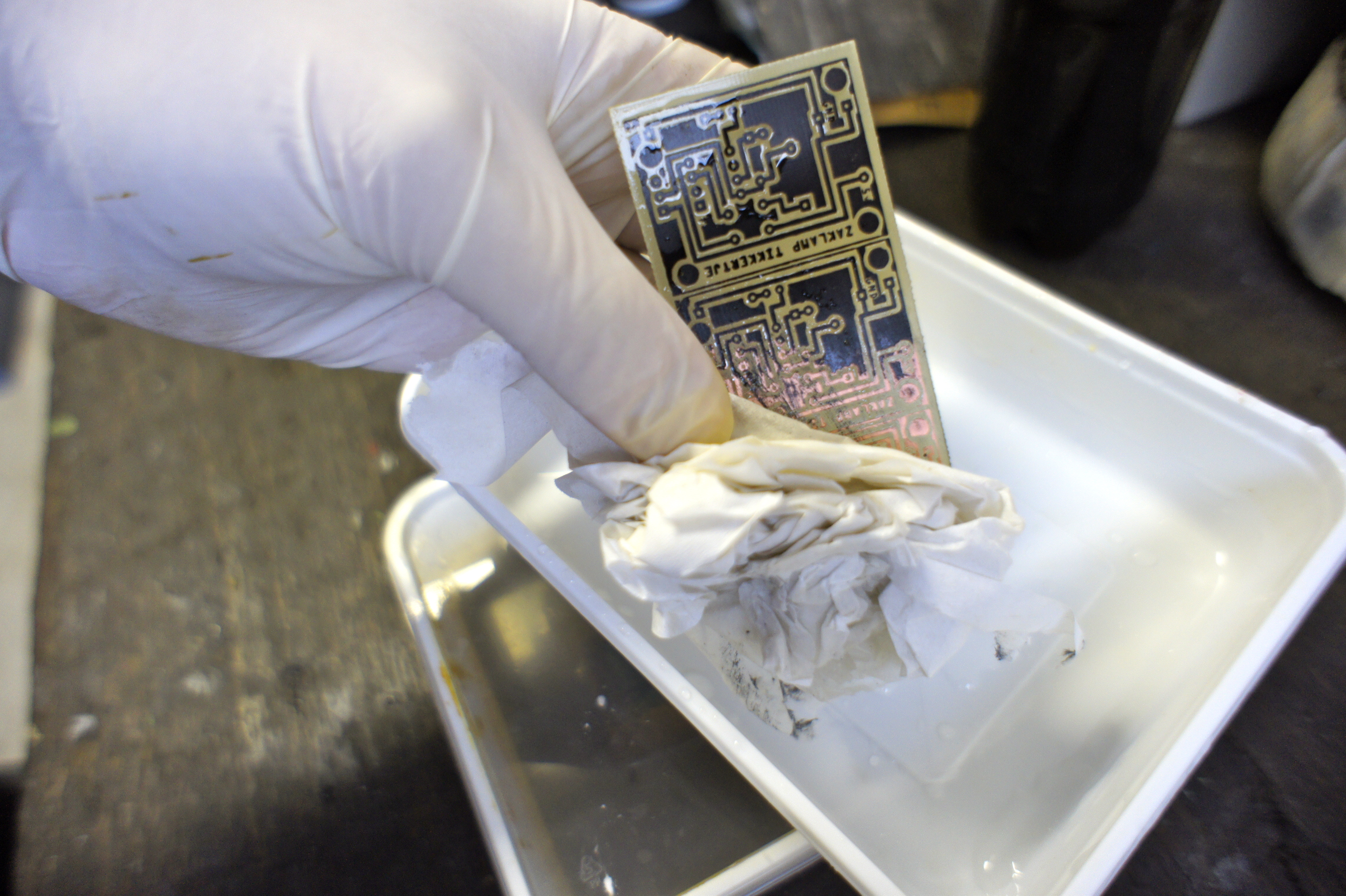
I heard the best solvent to clean the toner from your PCB is Aceton or nail-polisch remover. I had some other nasty stuff (trichlooretheen) that worked fine. All of these solvents are really bad for you, so use proper protection!
Just use a tissue or cloth with the solvent to wipe of the toner.
Protecting the copper
To protect the copper from corroding you can spray some protective stuff on it. You don't have to do this.
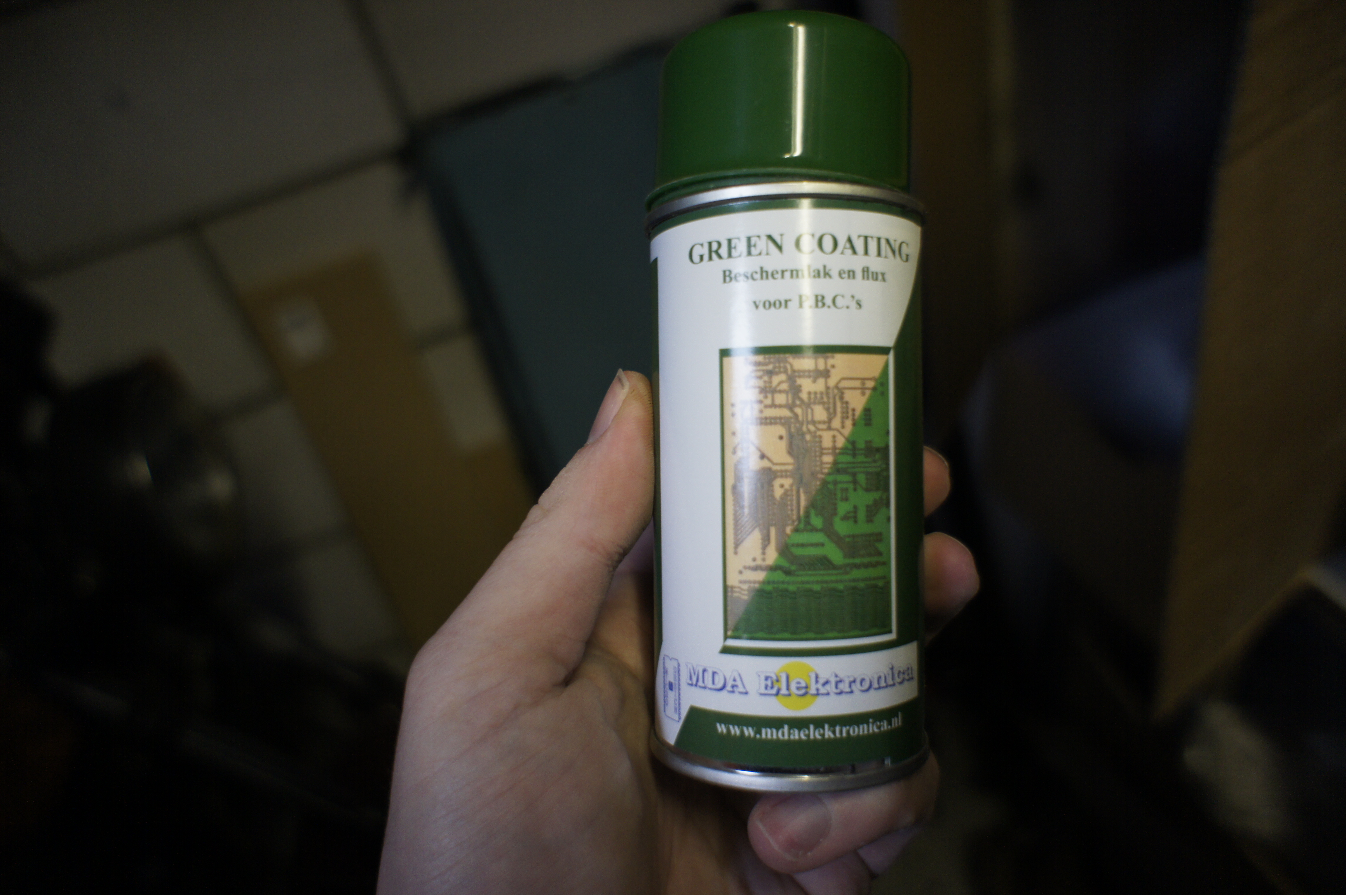
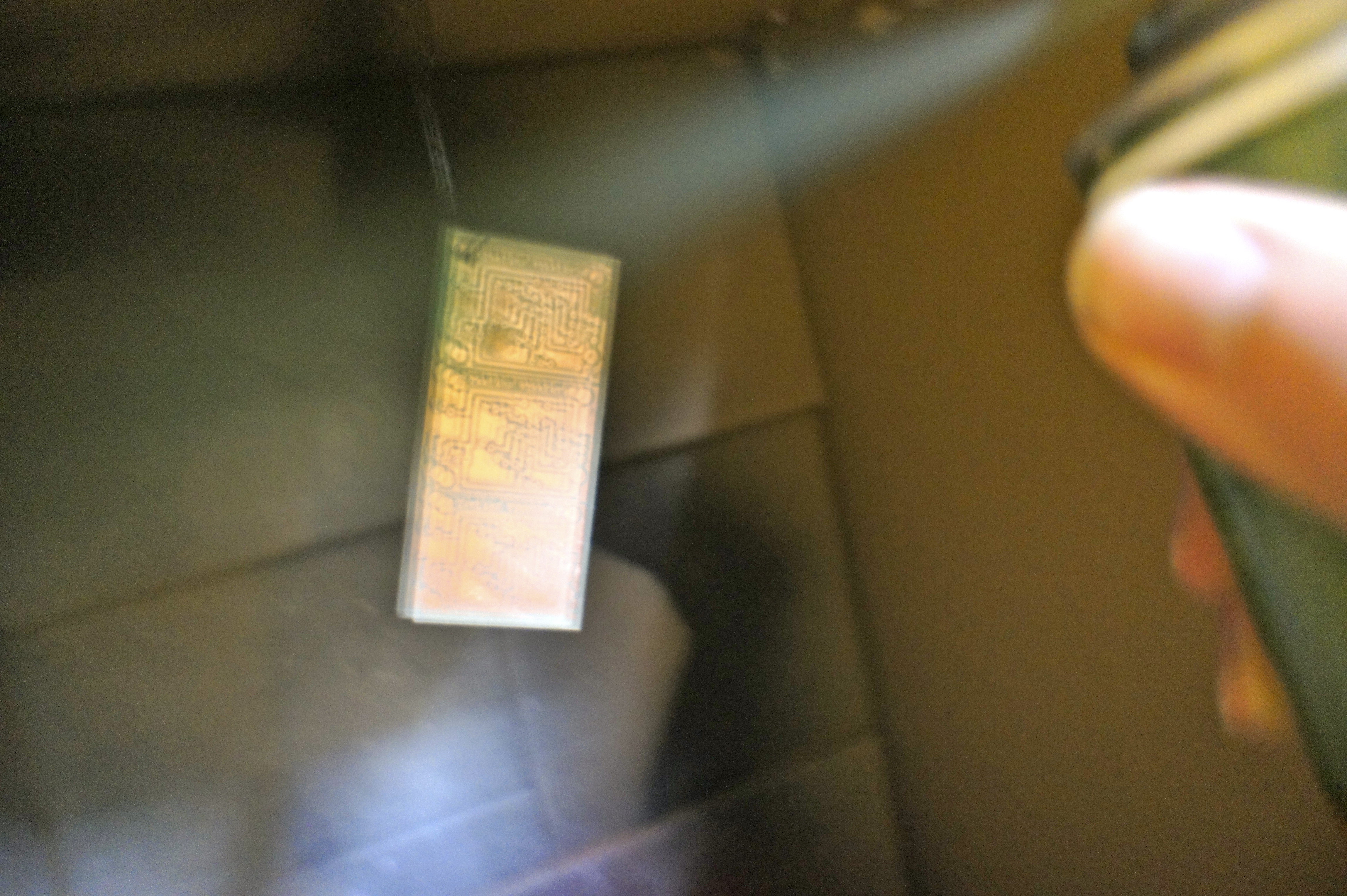
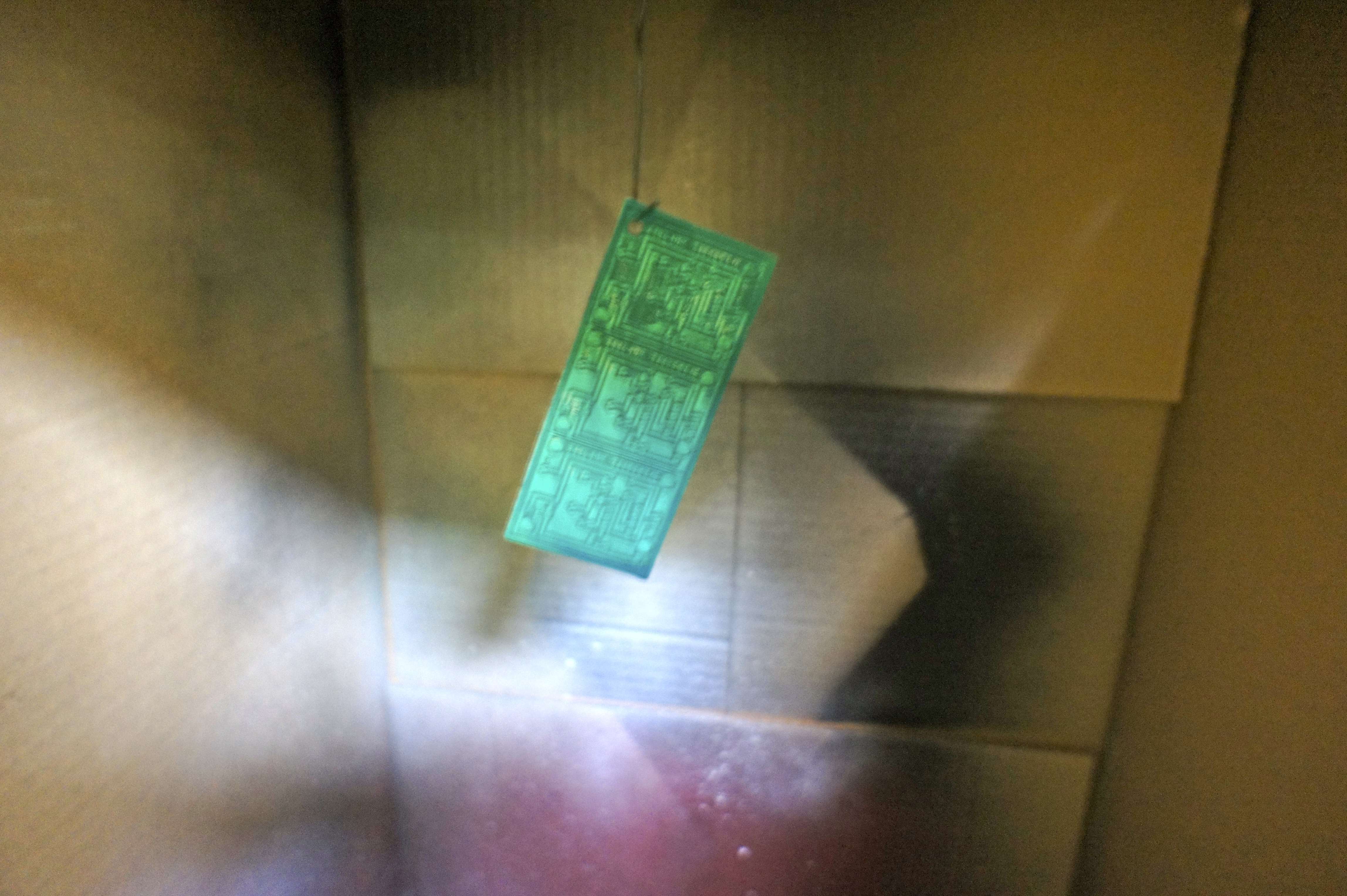
I first drilled one of the holes, so I can hang the PCB in my spray-booth (It is just a big box). Just spray a thin layer of the green stuff on the copper side of the PCB. (it is not so easy while making a photo with one hand) Now the hardest part: You have to let it dry! If you spayed so much as I did, it has to dry for a day :S
They look really profi in green!
Drilling the holes
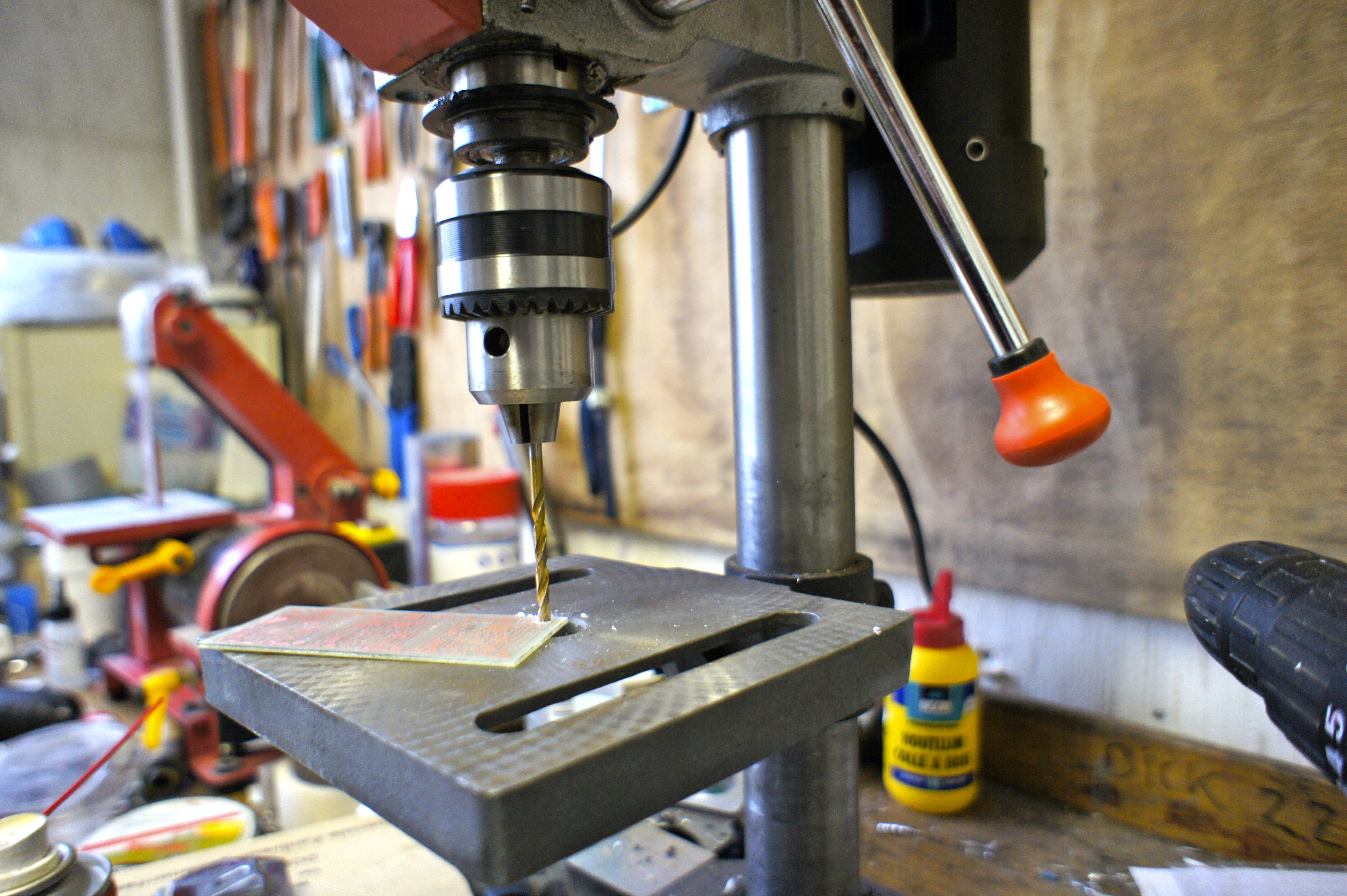
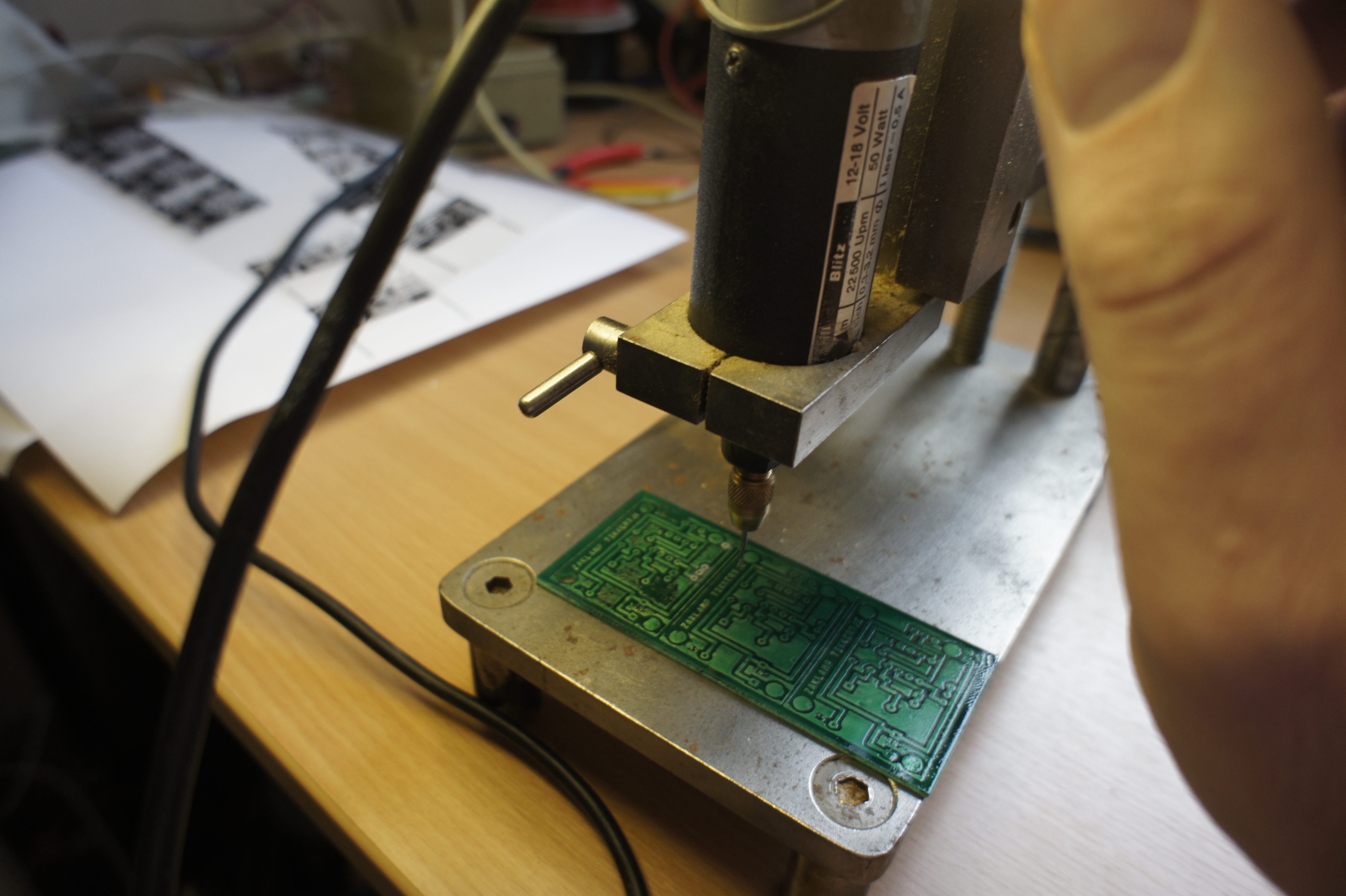
For drilling the holes I've got a really nice mini-drill-press, but a big drill-press or a Dremel also works fine. You will find that when you start with little pressure, the drill will automatically center on the holes.
For most holes I used a 0,8 mm drill. For the holes for the pushbutton I used a bigger one. (I think 1 mm)
Don't breath in the dust from the drilling.
Separating the PCB's
If you made more PCB's at ones, you might want to separate them by now. The breaking trick will probably not work anymore, so use a small saw, Dremel or steel-cutter to separate them.
The PCB is now ready to receive the parts!
Adding the Components

Checking the holes
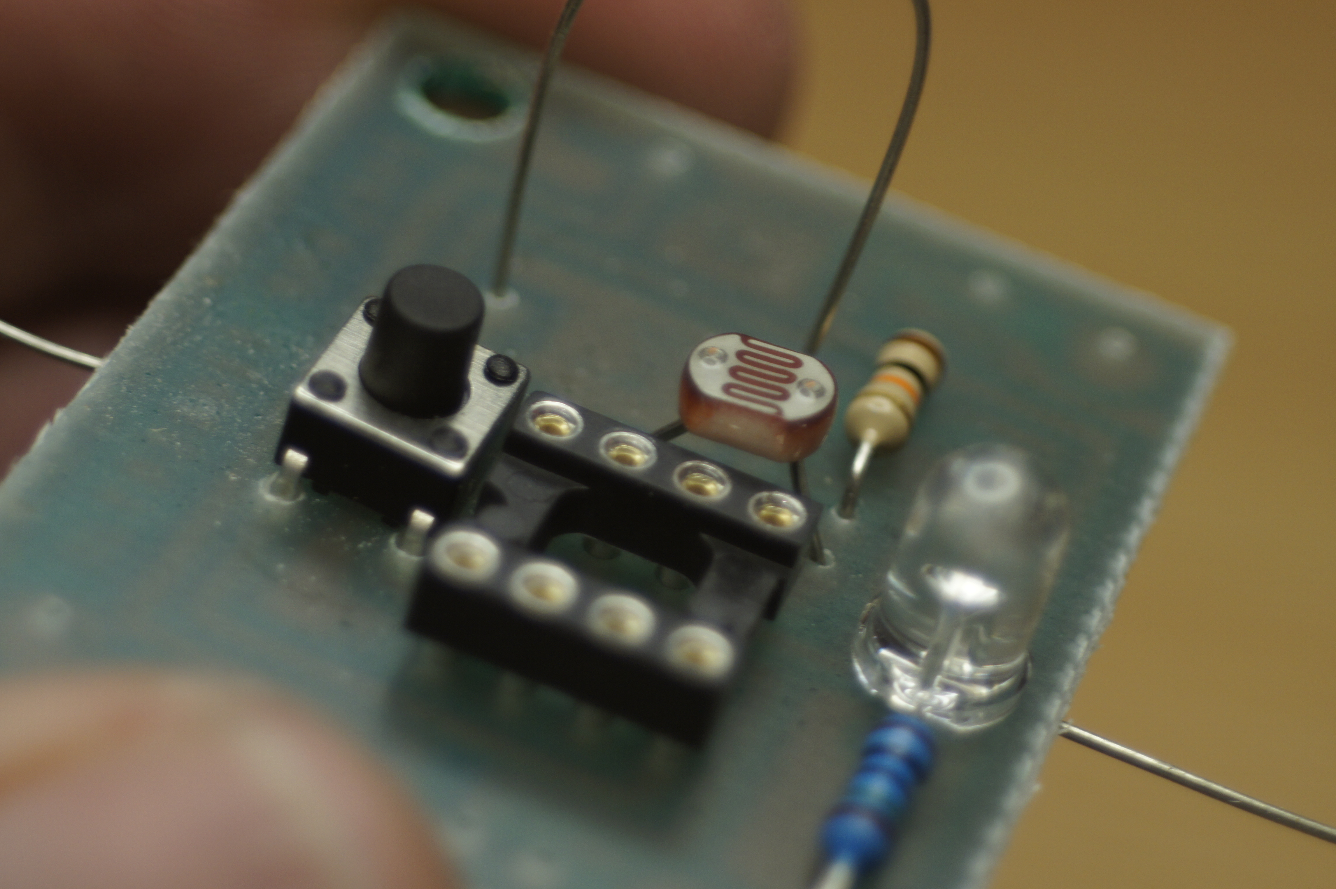
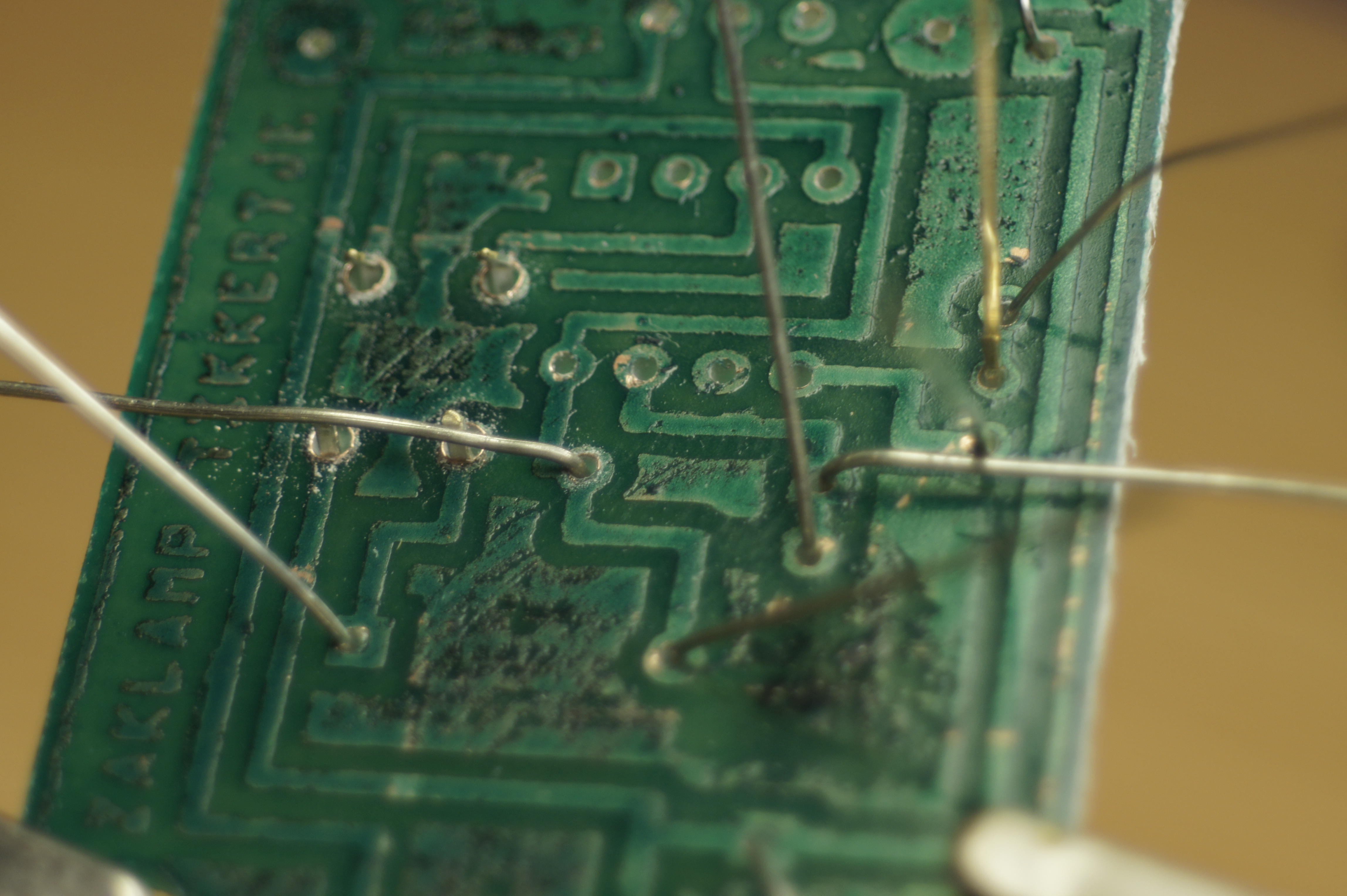
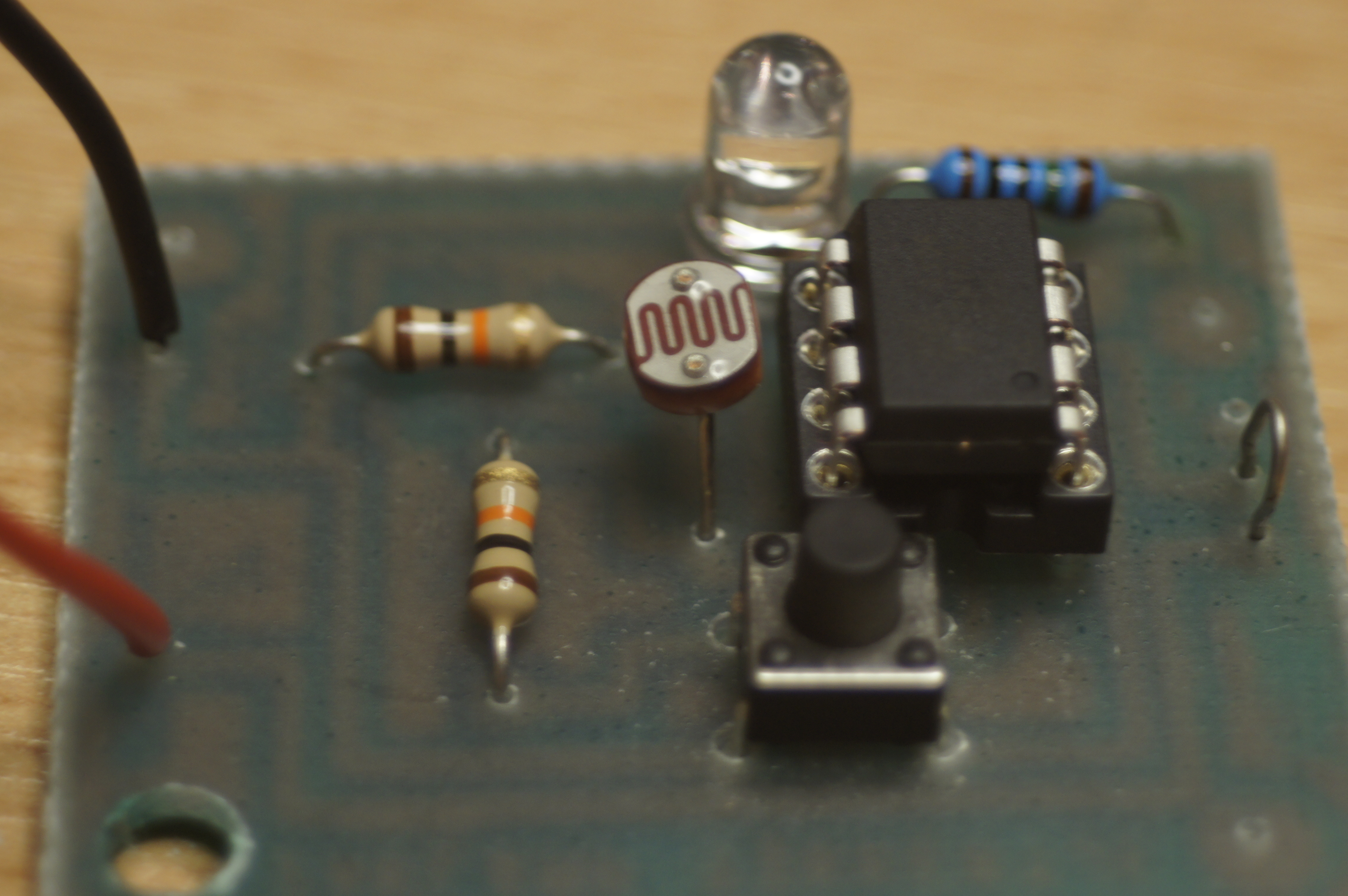
When you put all the components in the PCB, you can check if everything fits and if you didn't forget a hole (there is always one). It is helpful to use the PCB-view on Fritzing to help you remember where everything goes. If you hover over a part in Fritzing, it will tell you witch part it is.
Bending the leads
If you bend the leads a little bit on het back of the PCB, they will stay in place when you turn it over to solder.
Soldering the parts
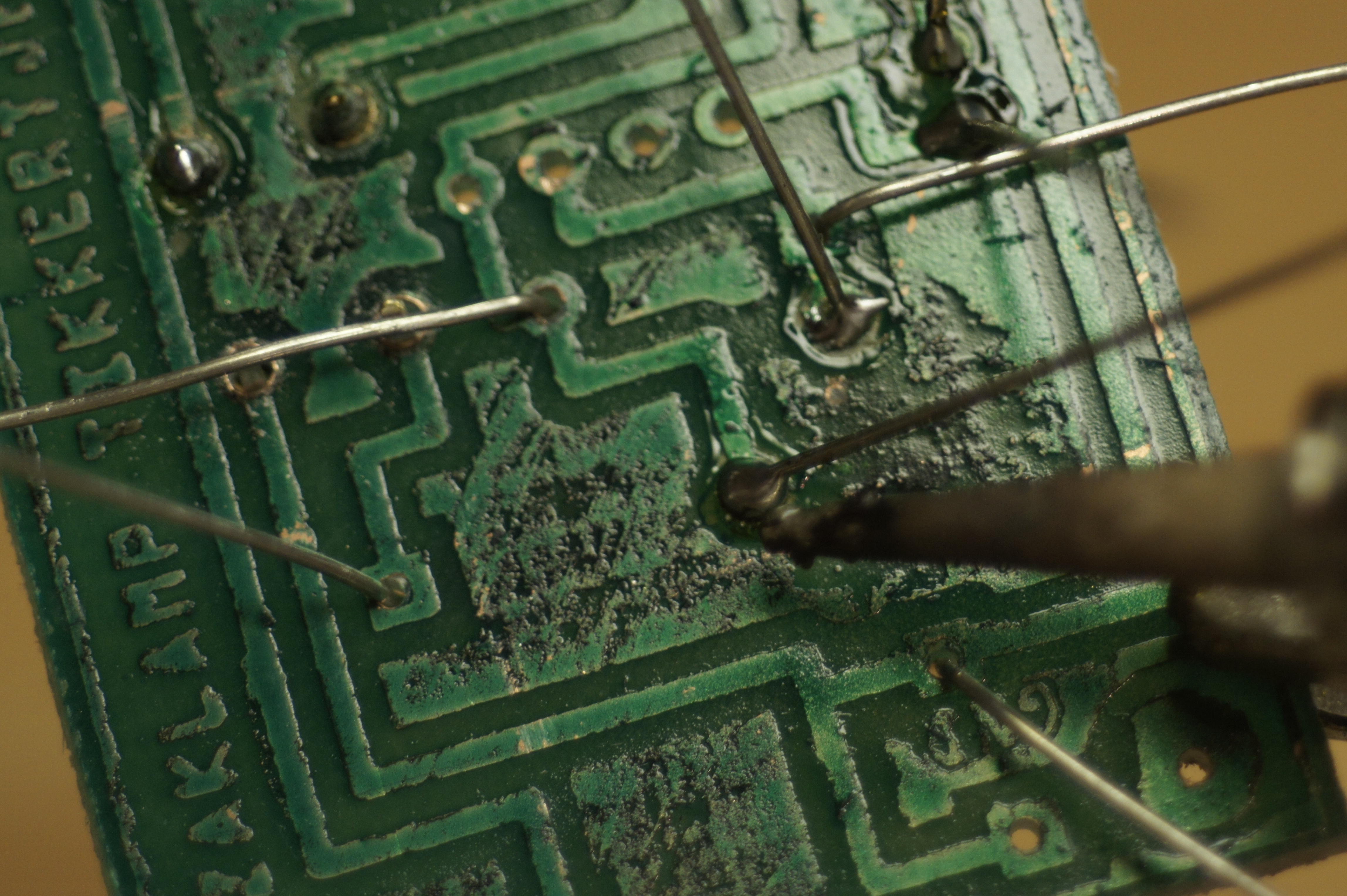
Now it is time to solder the parts. Heat the wire and the PCB with your soldering-iron and than ad the solder. If it flows an "sticks" on both the PCB and the wire, you did good.
Be sure not to breath in the fumes and be careful with the hot soldering-iron.
Shortening the leads
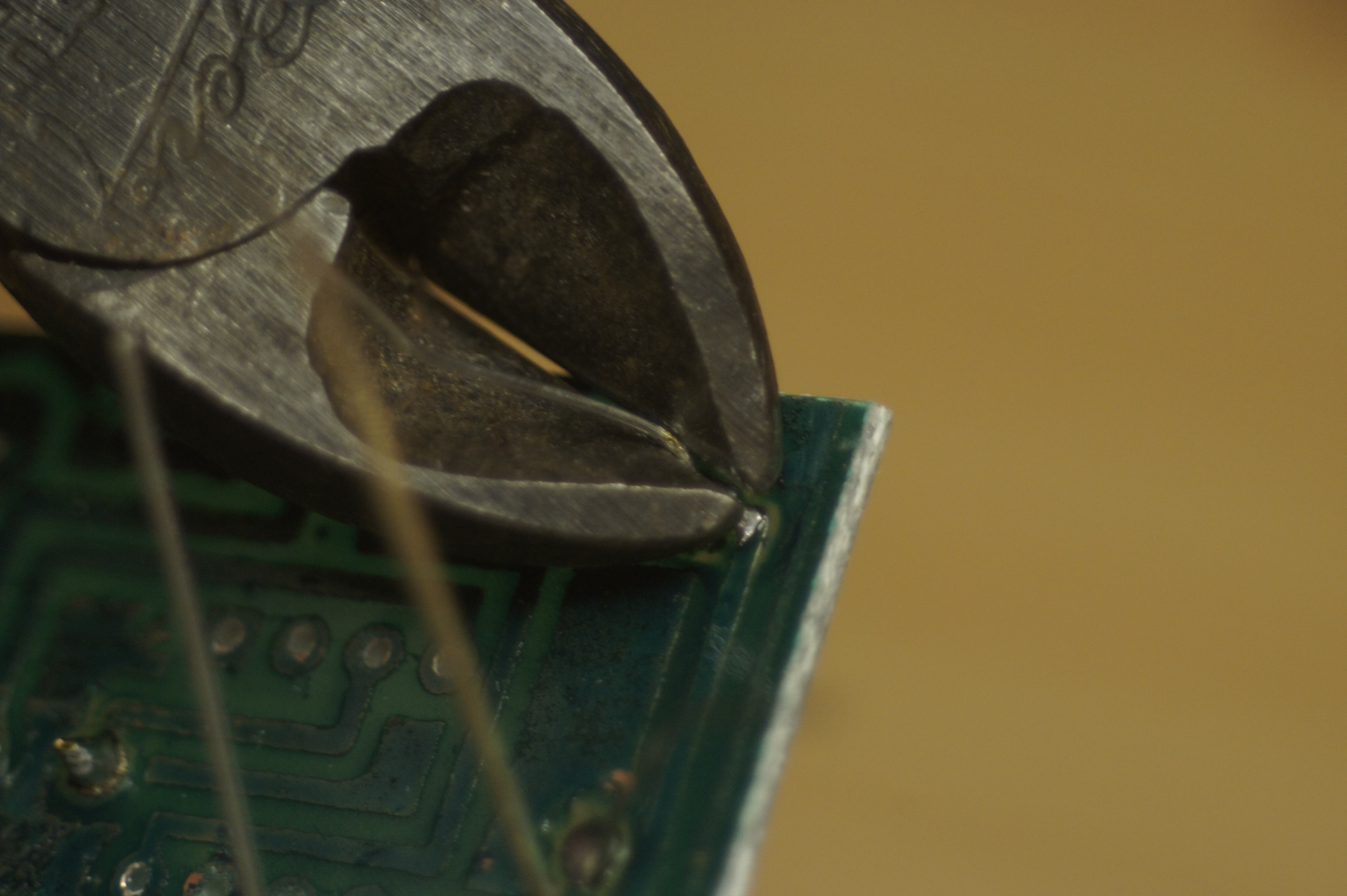
Now you can snip off the wires from the back.
For now I just shorted the on/off switch with a wire and I added two
Placing the ATtiny
If the PCB is finished you can place the ATtiny chip in the holder. Often you have to bent in the legs a little bit to fit. Pin one is marked with a dot. Be sure to put the ATtiny the right way in het holder. If you do it wrong, you will probably blow up the ATtiny.
Try-out
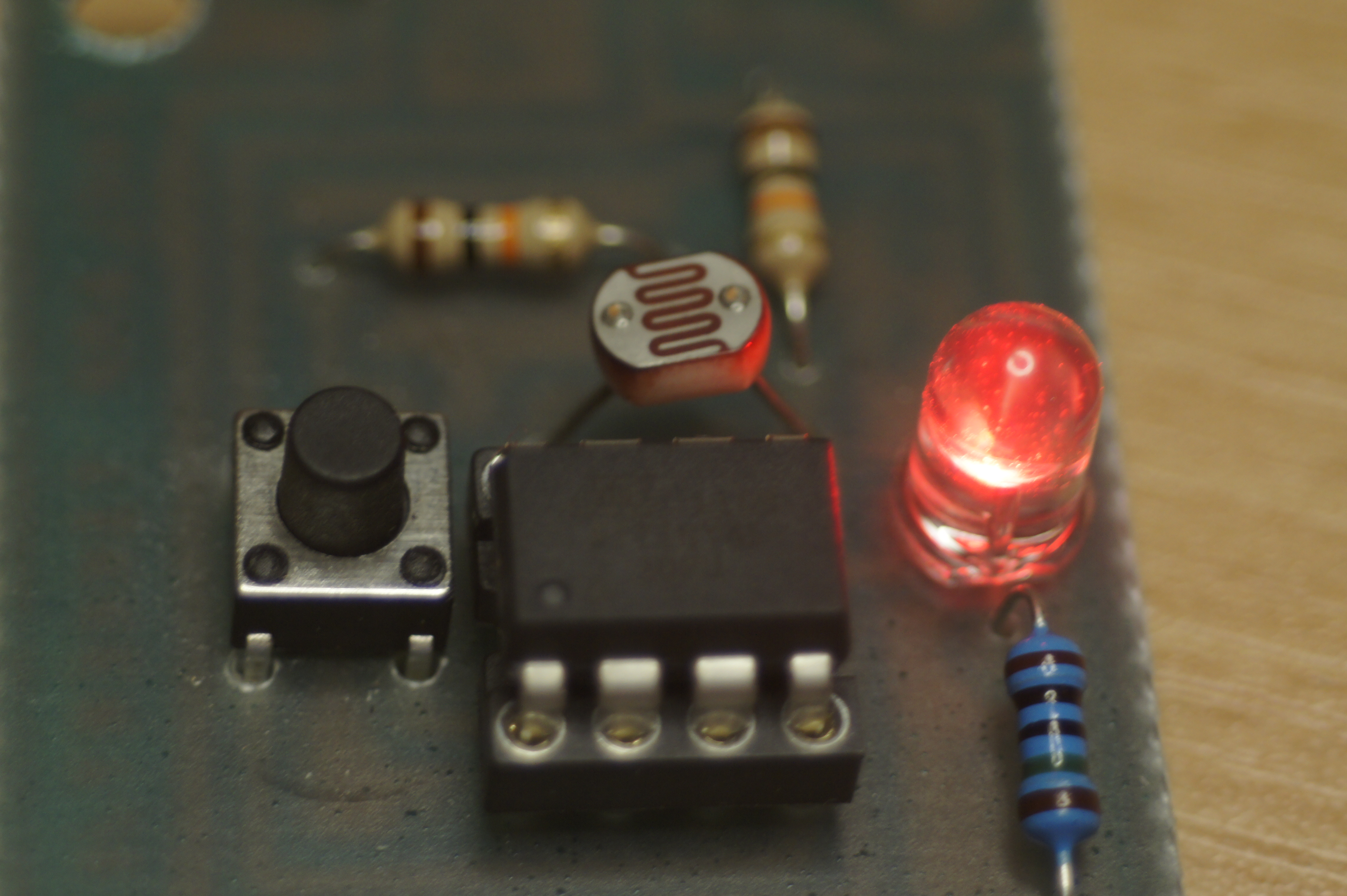
Now we turn off the lights and put some power on the wires to check if it works. And...
... Yes!!!
... Yes!!!
The Casing (the Outside)

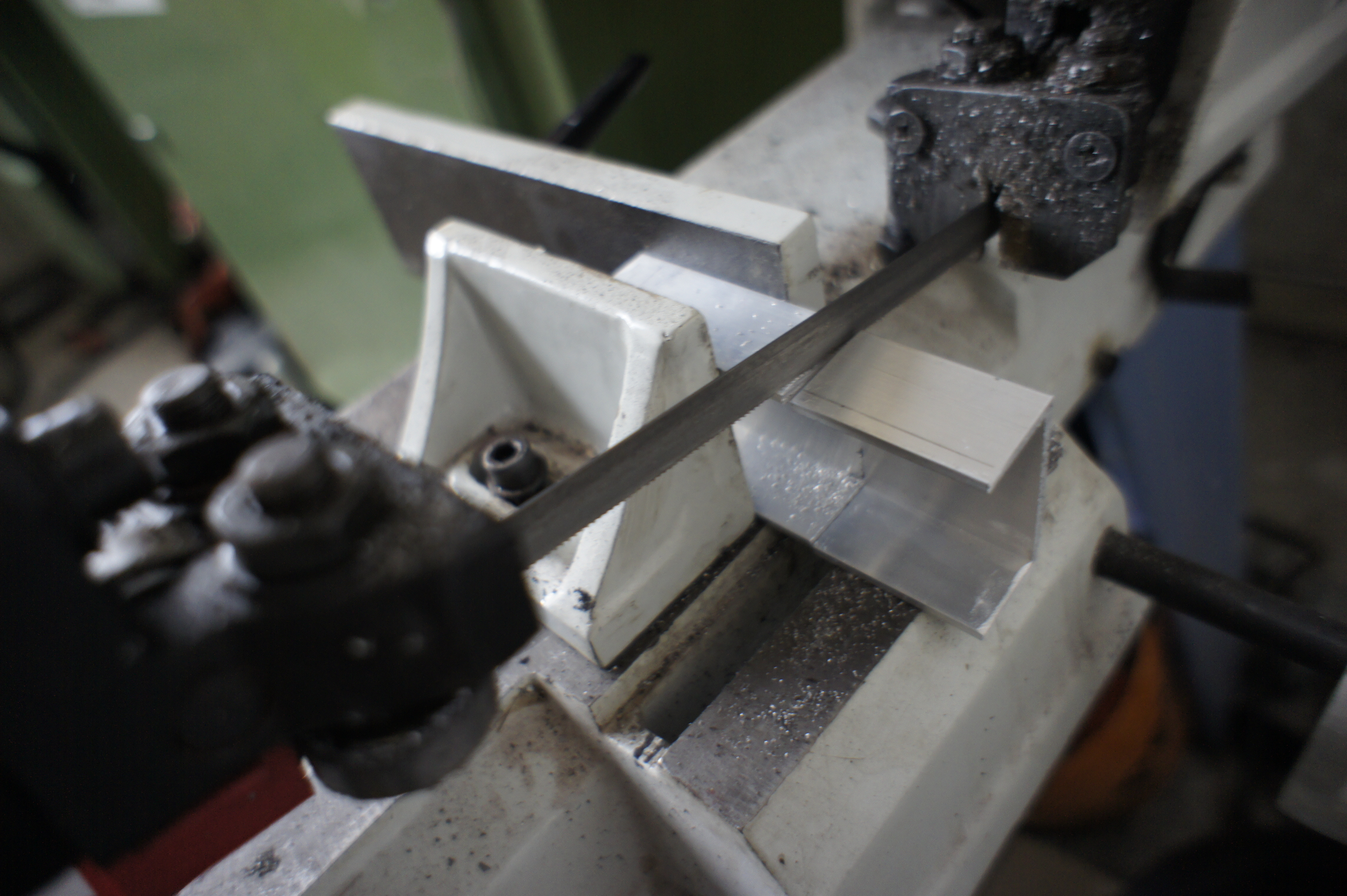
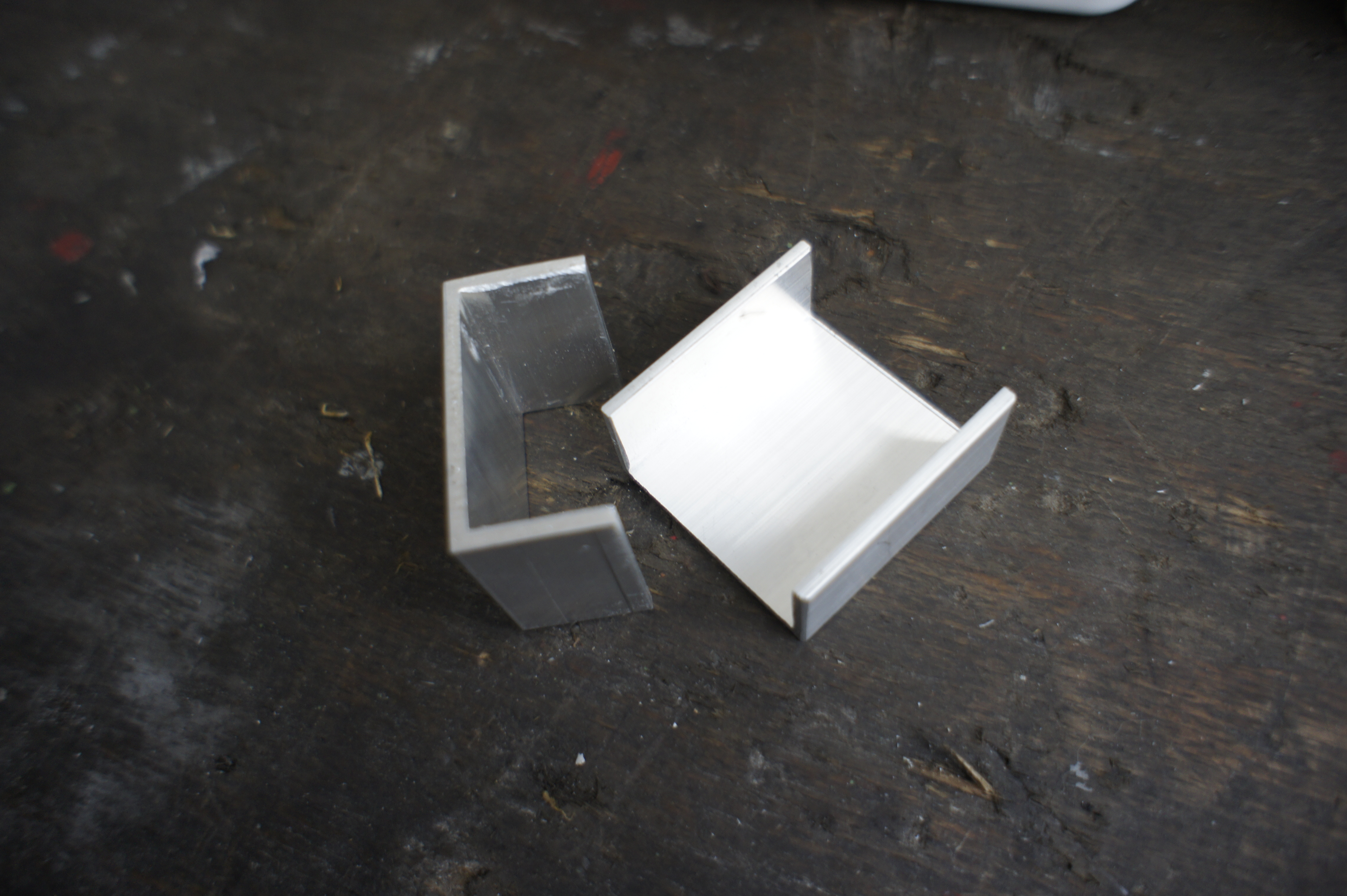
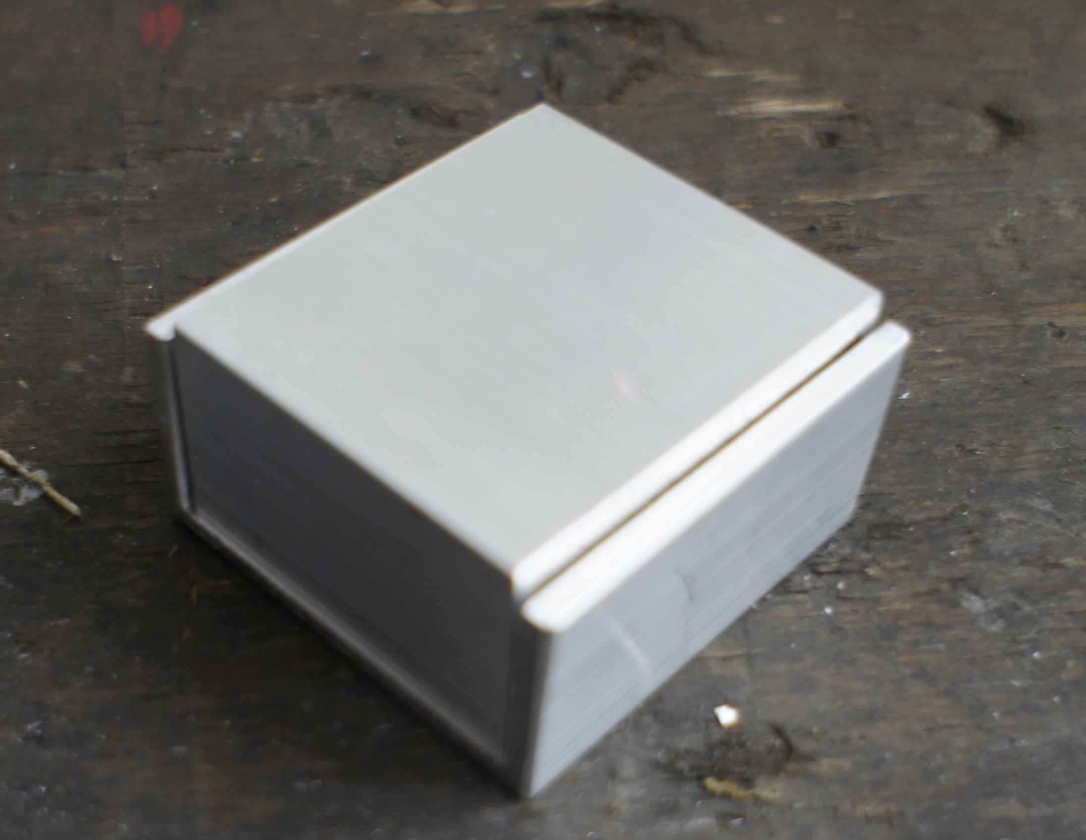
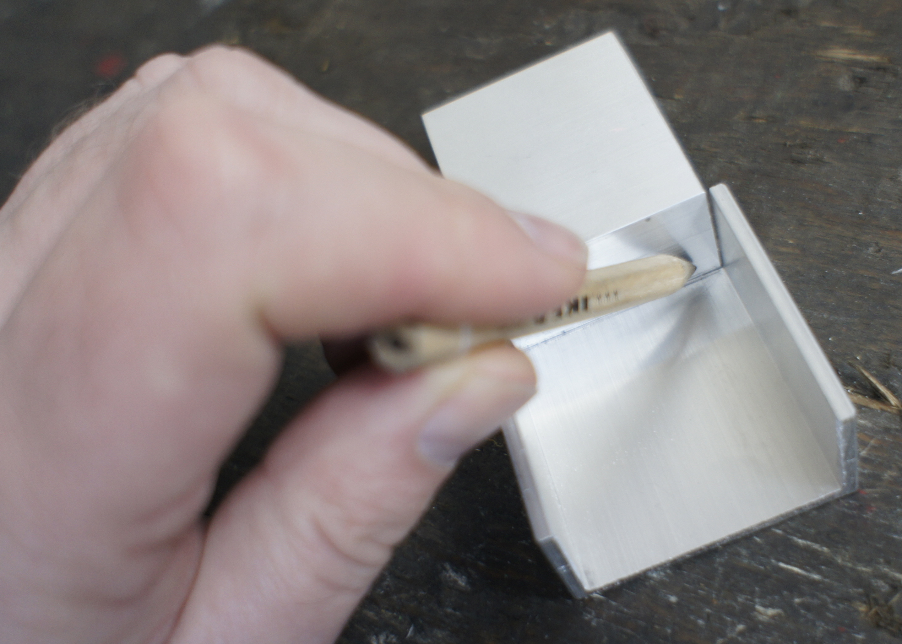
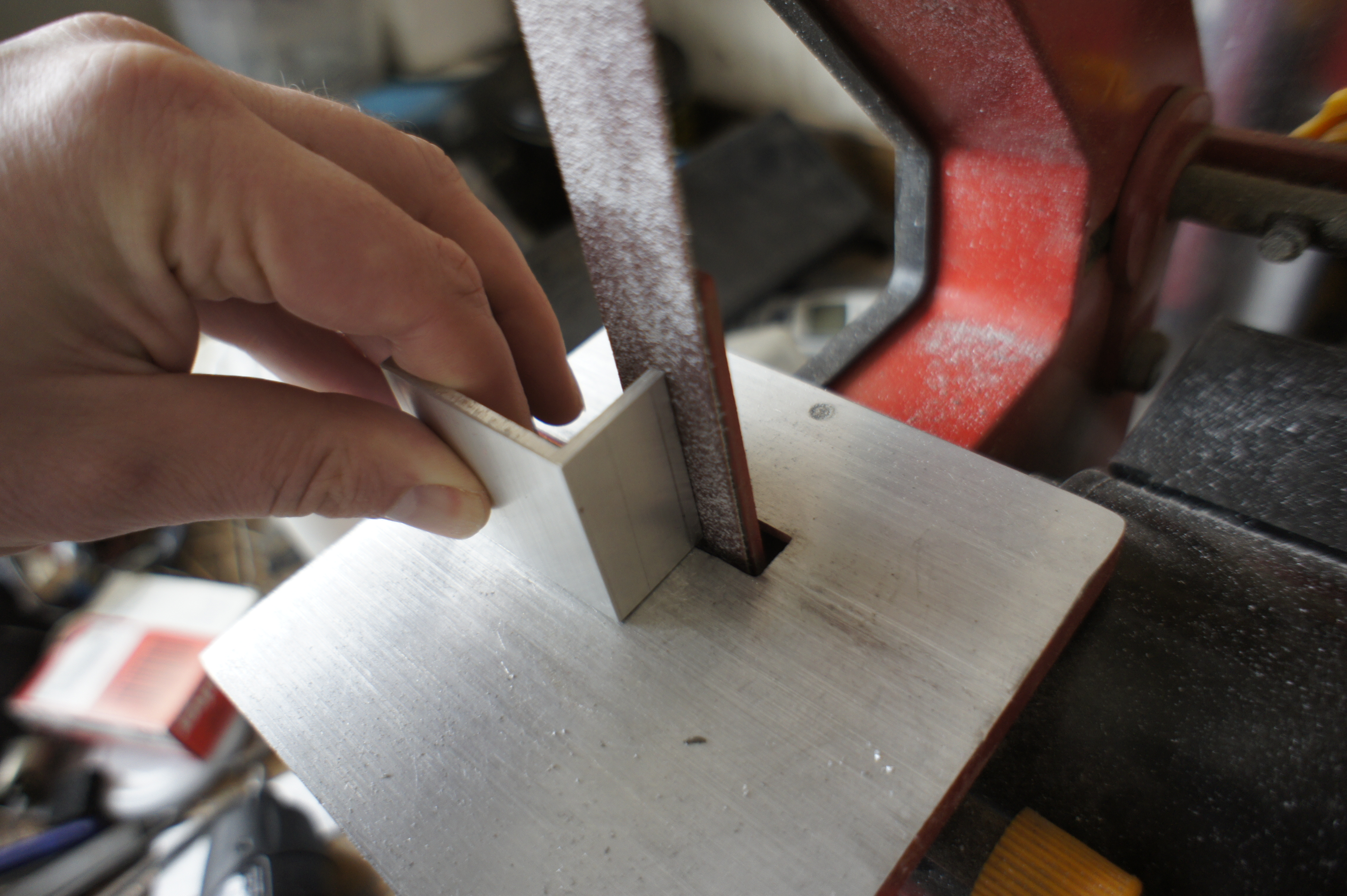
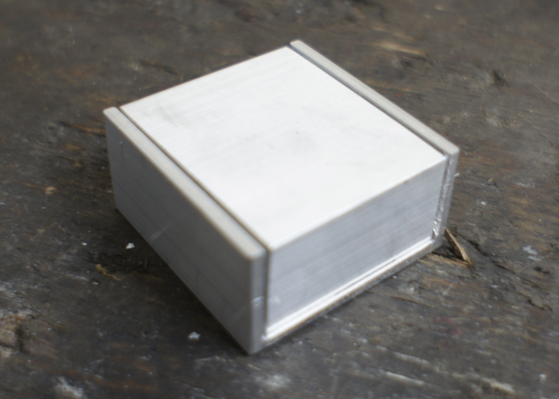
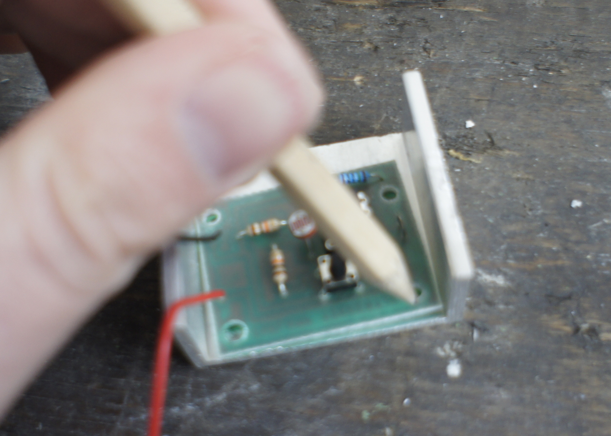
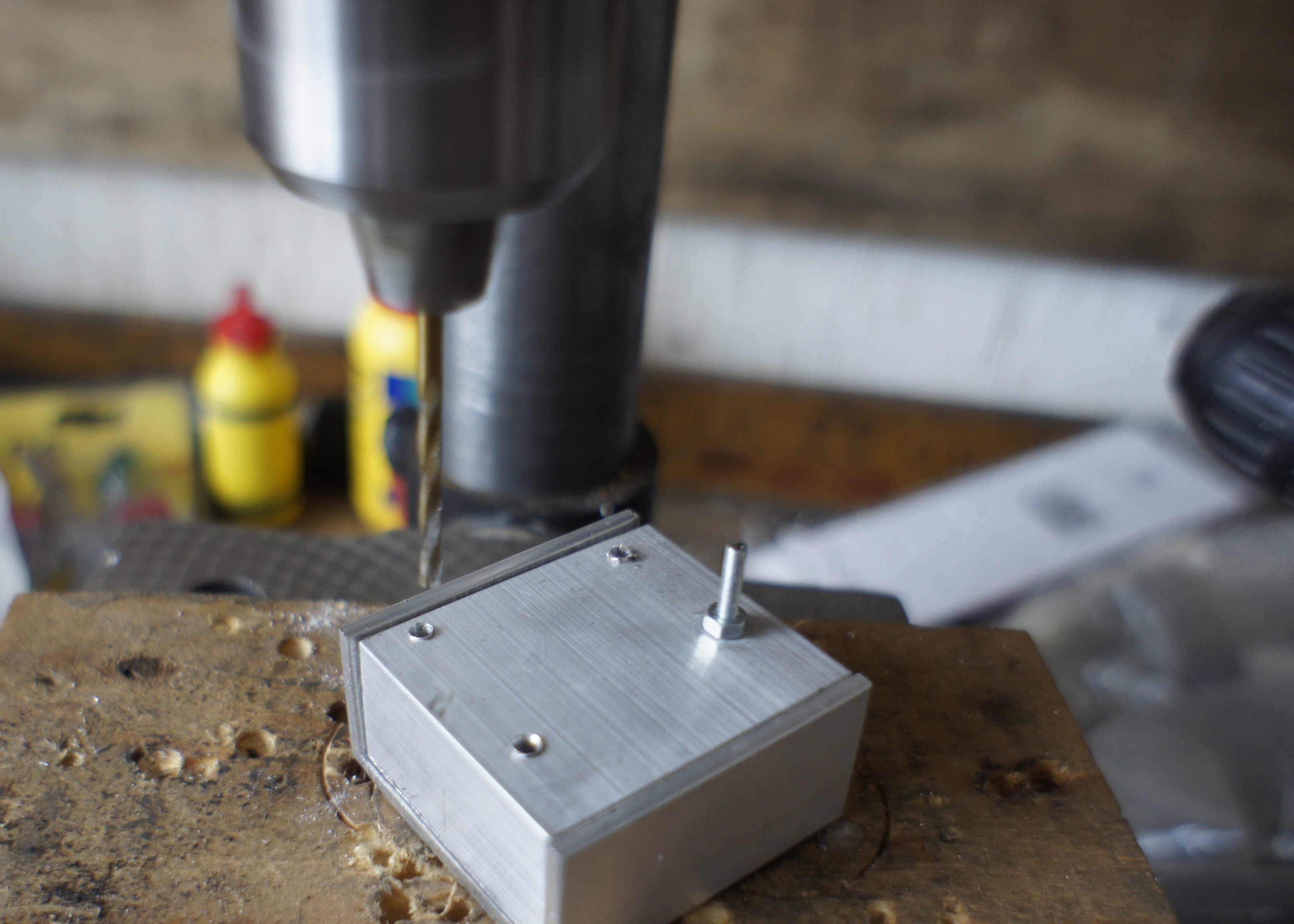
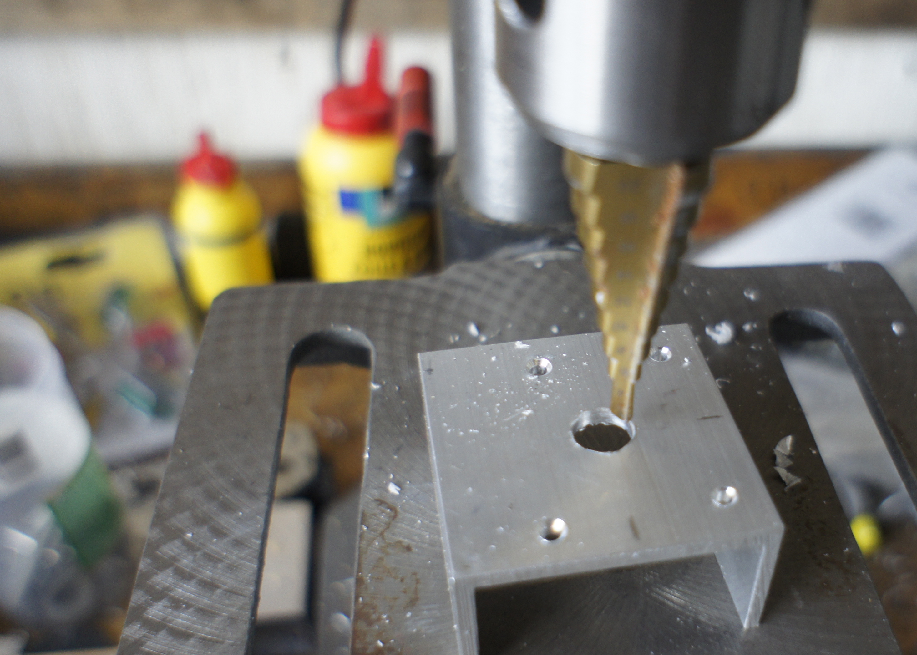
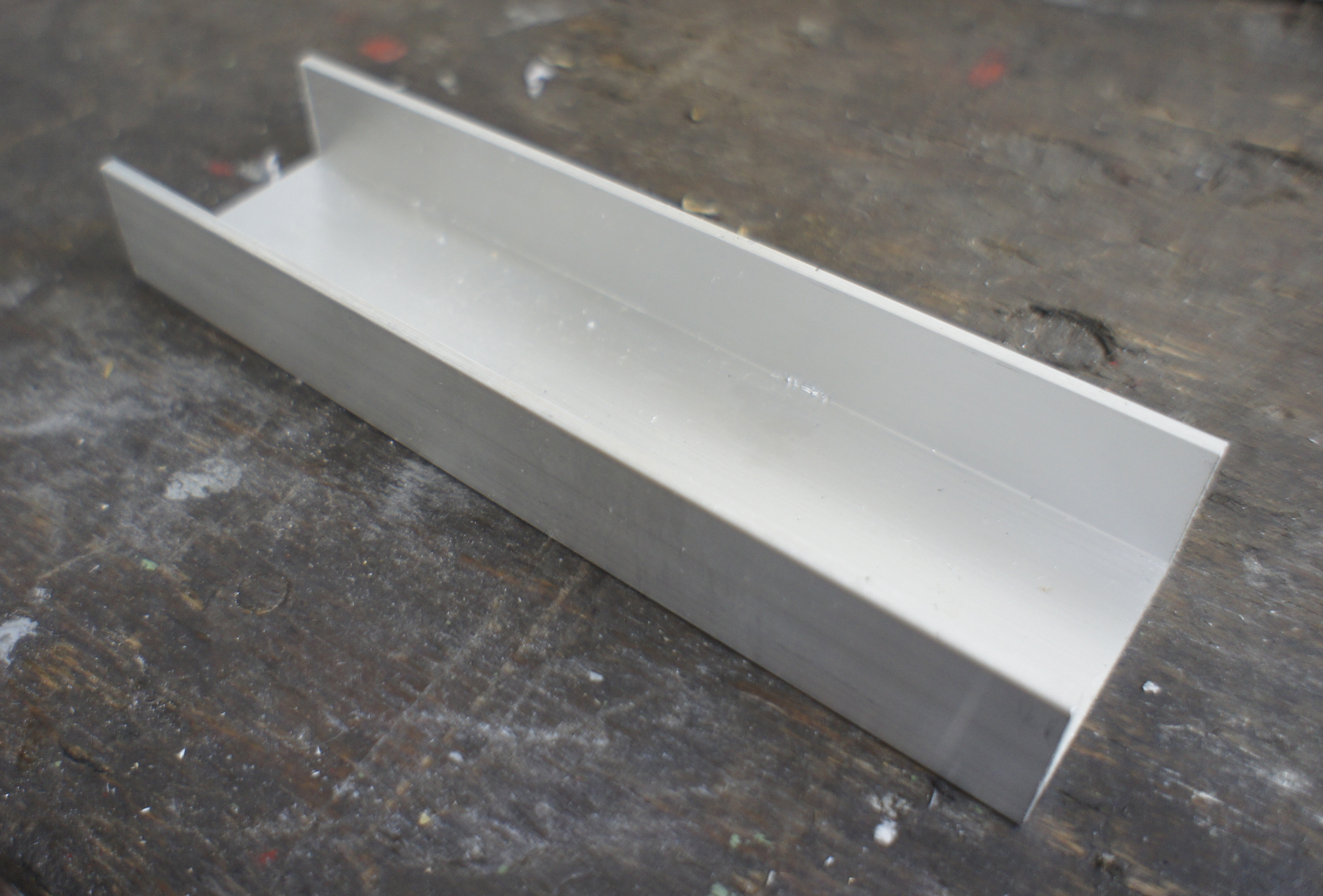
To house the project I used some aluminum U-profiles that I have laying around from an other project. (it was approximately 45mm wide and 25mm high)
The measurements
The PCB just fits. I want two pieces of U-profile to fit over each other.
One piece must be cut the exactly the same length as it is wide. The other piece must be two times the thickness of the material shorter.
I always like to cut the material a little bit bigger than I need and then vile or sand it to the right dimensions. (this time I didn't and it shows)
The hight of the small piece is still one time the thickness of the material to high. If you put the two pieces next to each other, it is easy to draw where you must cut it. I started sanding it of, but did use the saw, when it took me to long. (and the aluminum got to hot to hold)
Now the two pieces fit into each other very nice.
Drilling the holes
To put everything together, we need to drill some holes.
The holes in the PCB dictate where the holes in the casing should come. So put the PCB in the bottom casing (the small U) and draw where the holes should come.
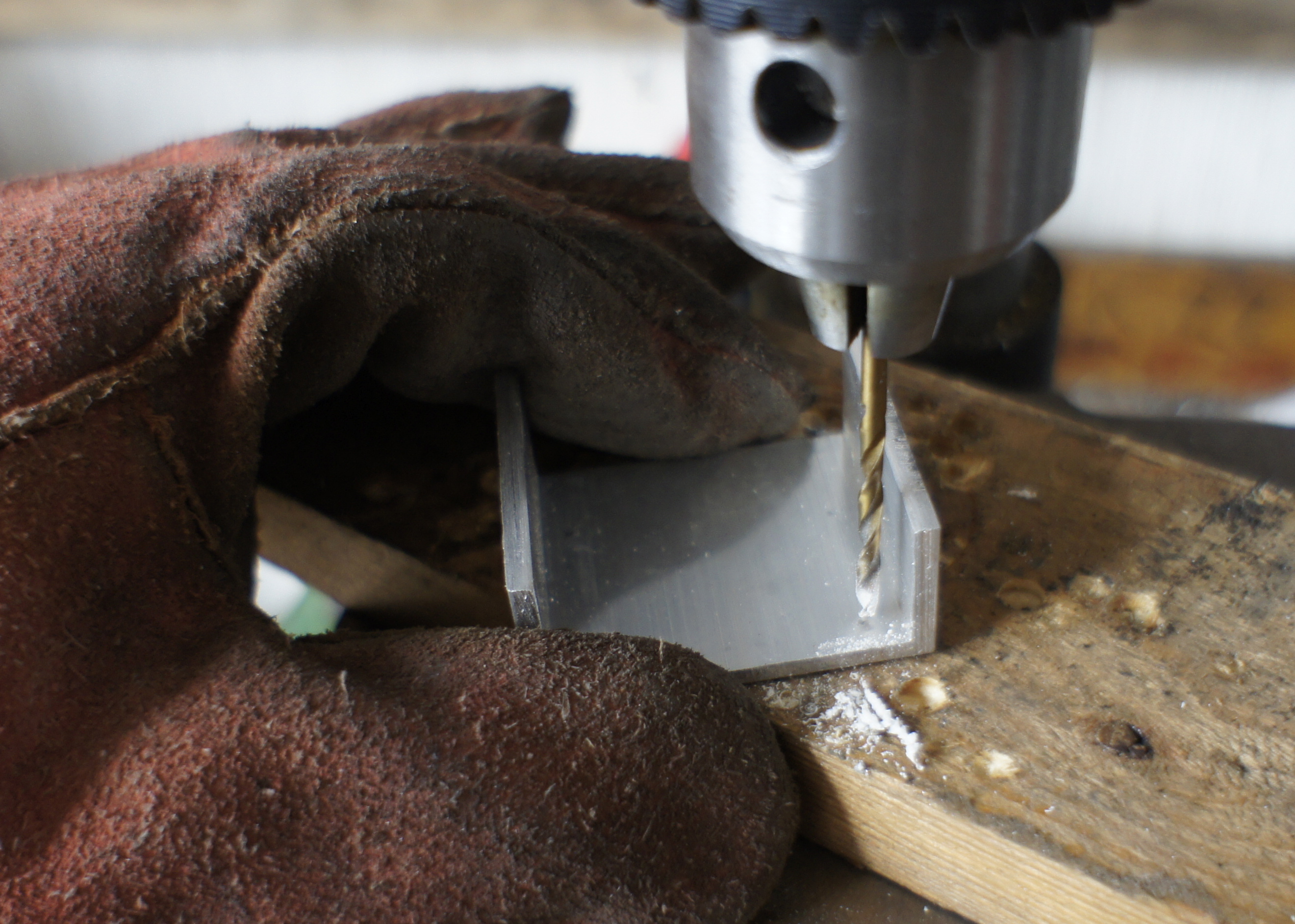
I'm going to put everything together with M3 bolts so I drill 3mm holes. (I always wear thick gloves when I drill small pieces like this. Sometimes the drill grabs the piece and it can hurt you badly if you don't wear gloves)
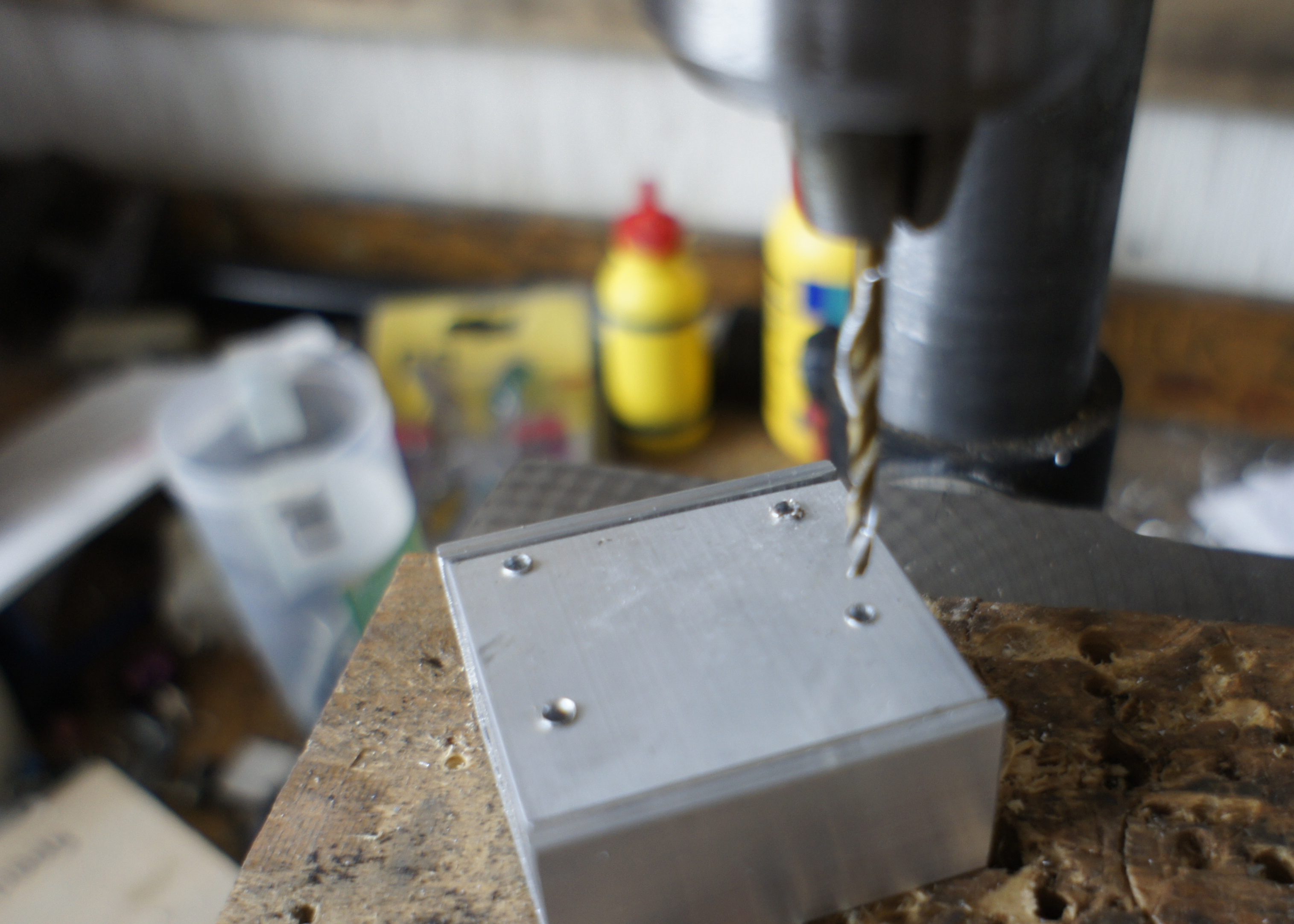
Next I put the two pieces together (upside down) and I drill the first hole all the way trough the hole I already drilled (in the bottom piece) in the top-U-piece.
Now I connect the two pieces with a M3 bolt, to make it easier to drill the other tree holes. The two pieces stay nicely together this way.
There must be one more hole in the top. This hole must be right above the light-sensor on the PCB. So put in the PCB and mark it out.
I made this hole 14 mm with special drill. It must be big enough to put the top of a finger trough it to push a button.
The Battery Compartment

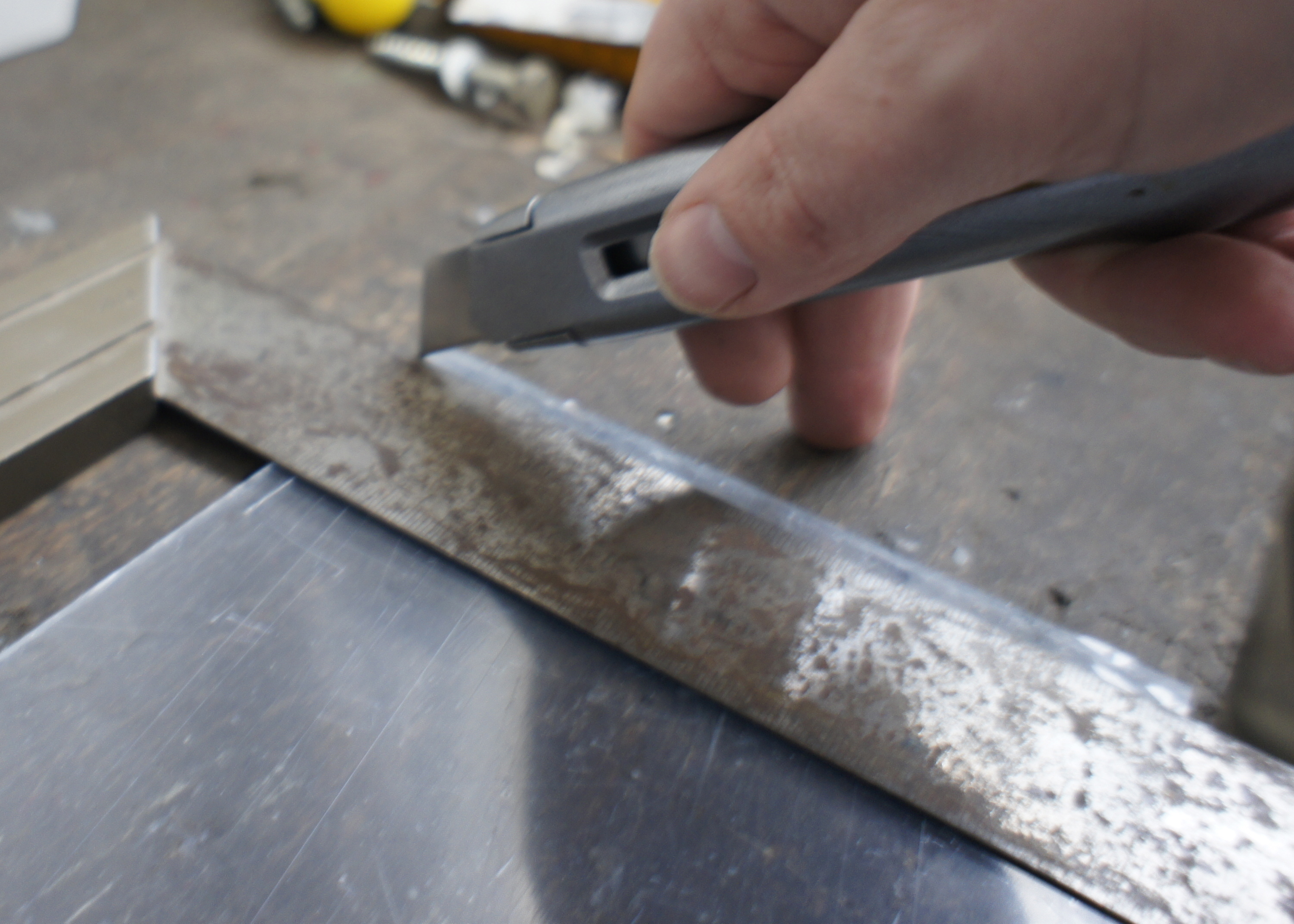
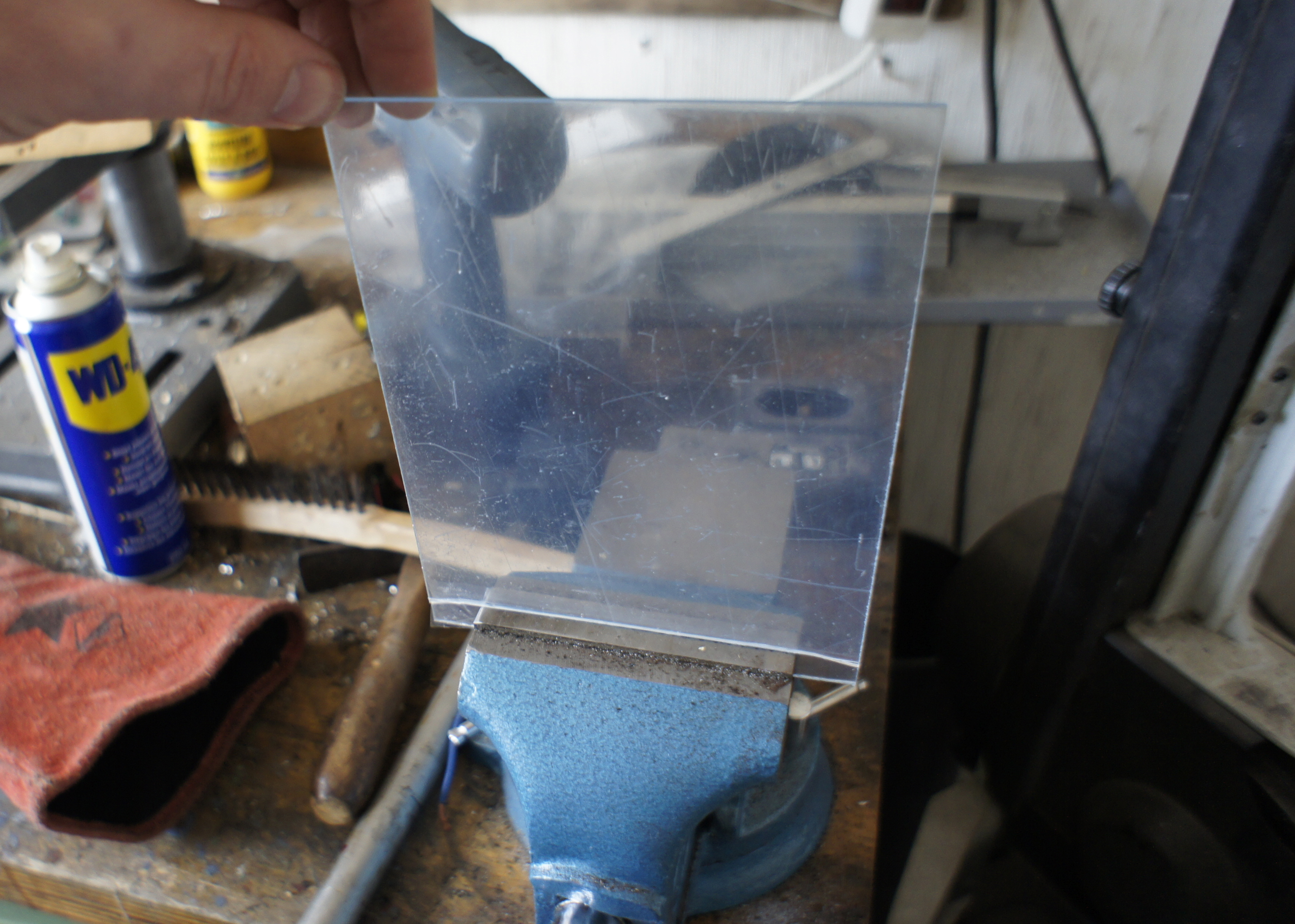
Cutting the acrylic sheet
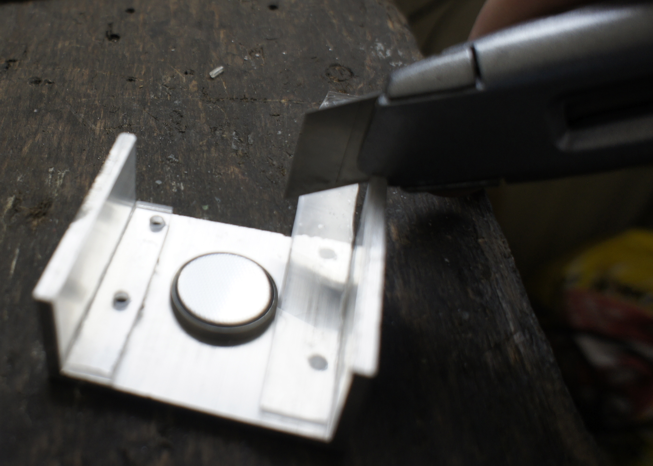
There is a really easy way to cut acrylic material. You just cut into one side with a sharp knife and than you break it in a vise or on the edge of a table.
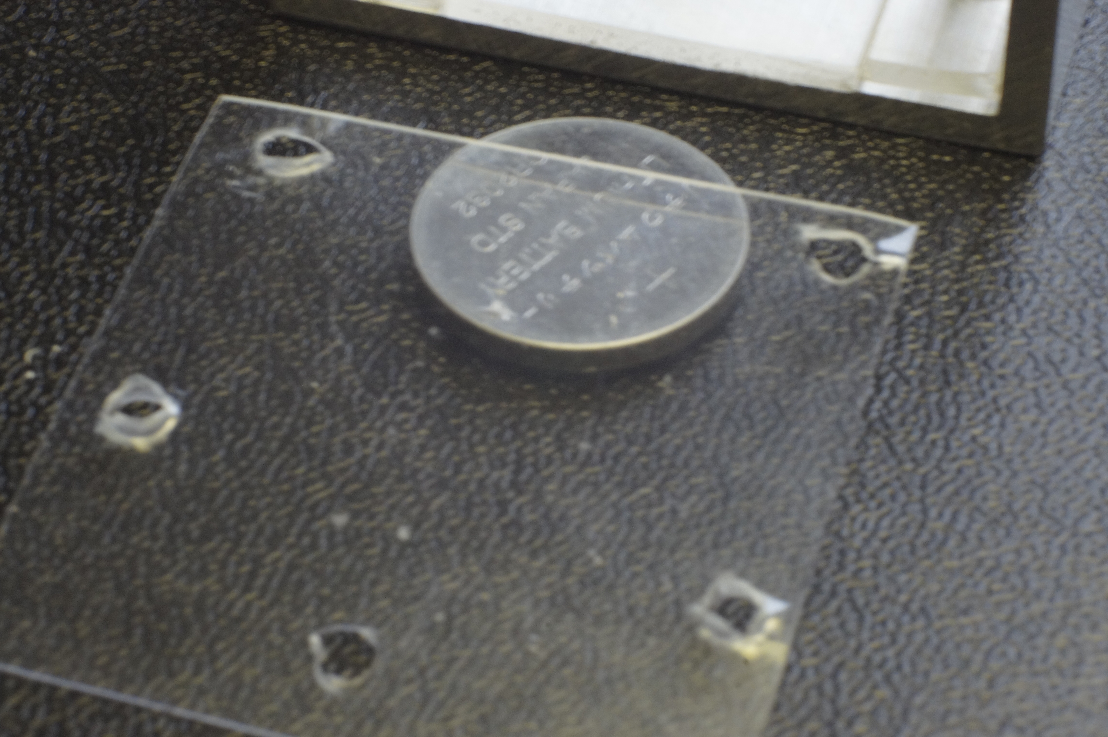
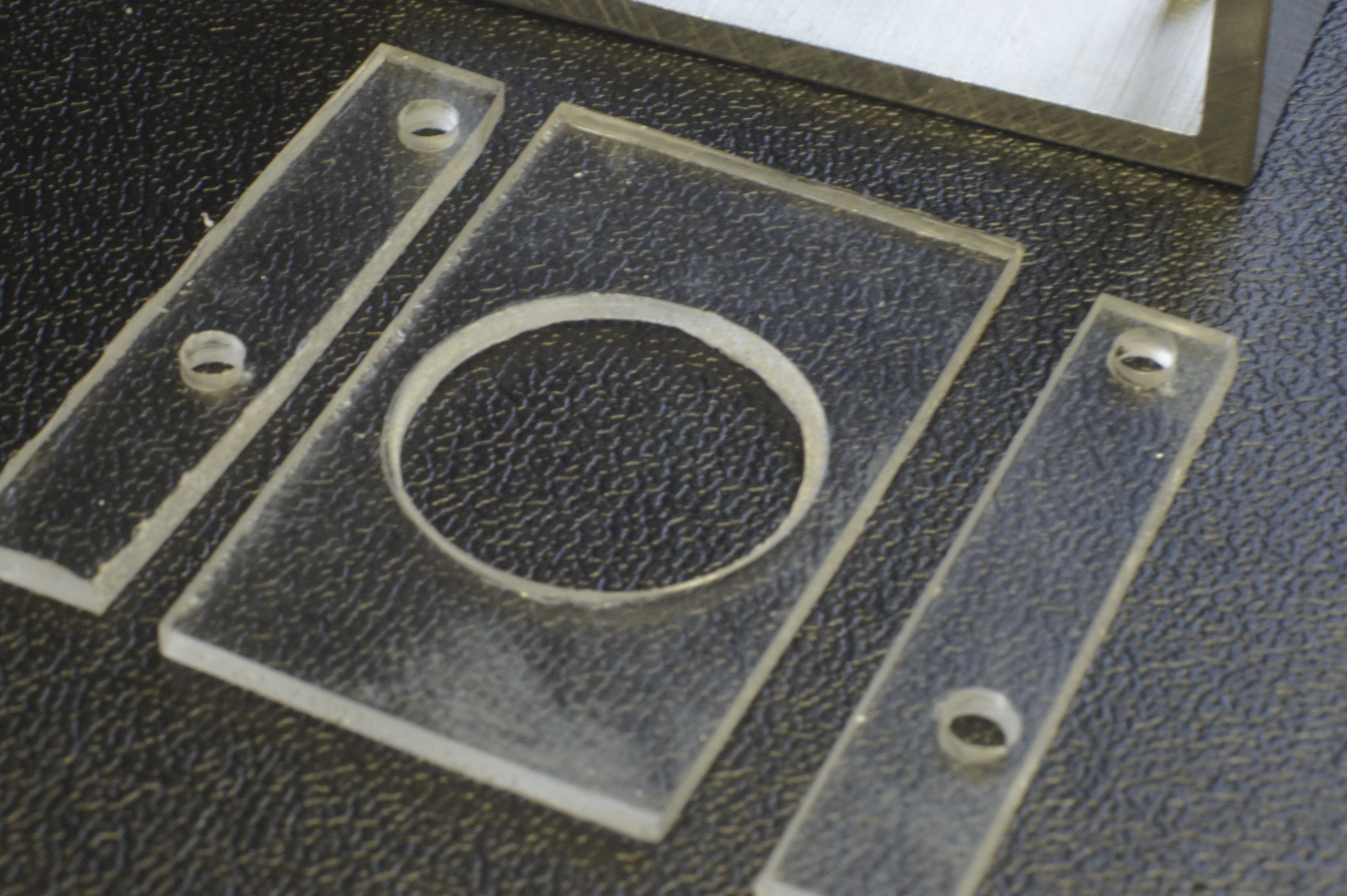
For the battery-compartment we need to small pieces on the sides and a big piece with a hole for the battery in it, in the middle. I first cut off a small strip for the sides. When I put it inside the aluminum profile, I can see exactly how long it should be and cut it there also. I need two pieces like that.
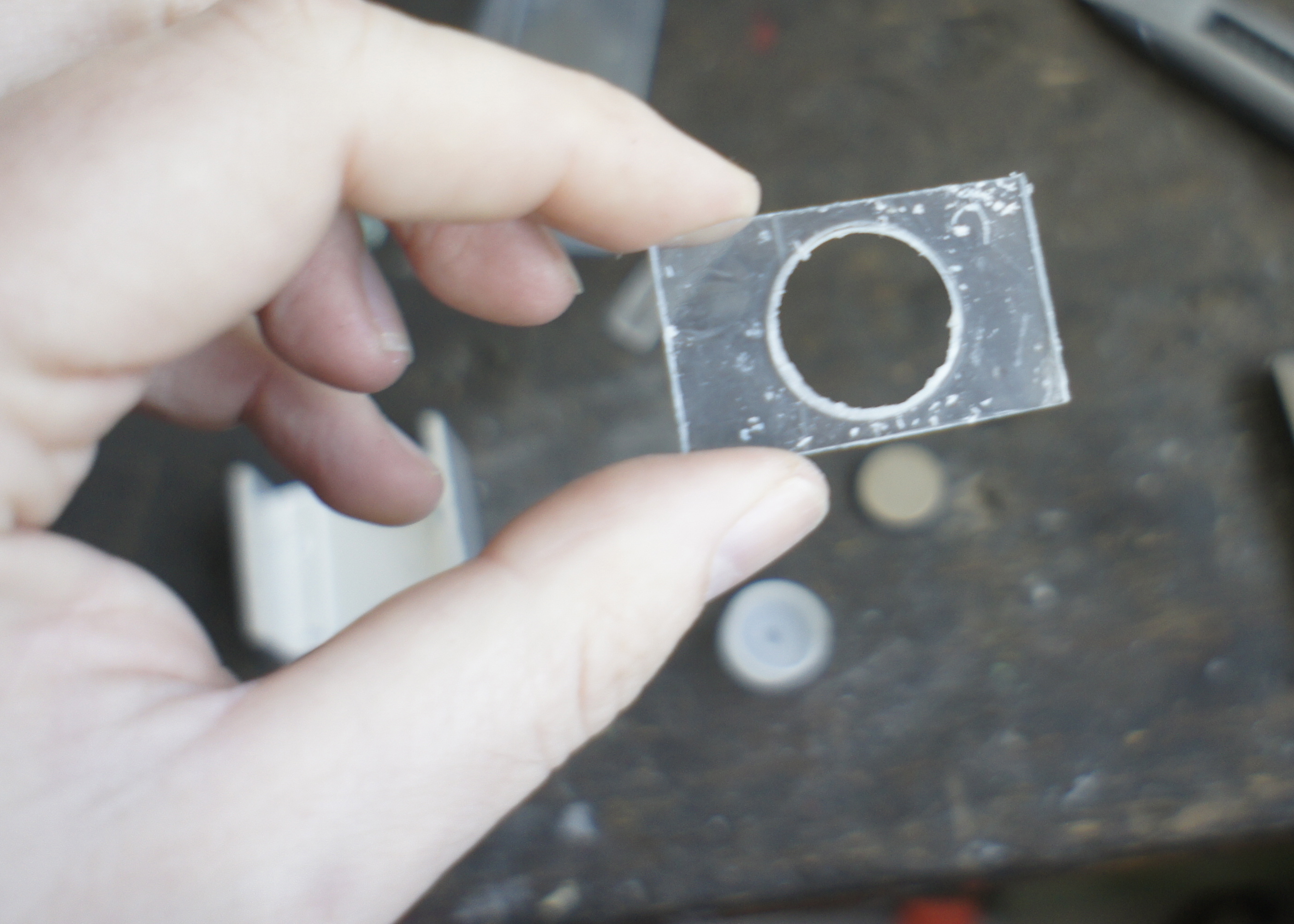
The piece in the middle should fit exactly in between the two small pieces en must be bigger than the size of the battery.
Drilling
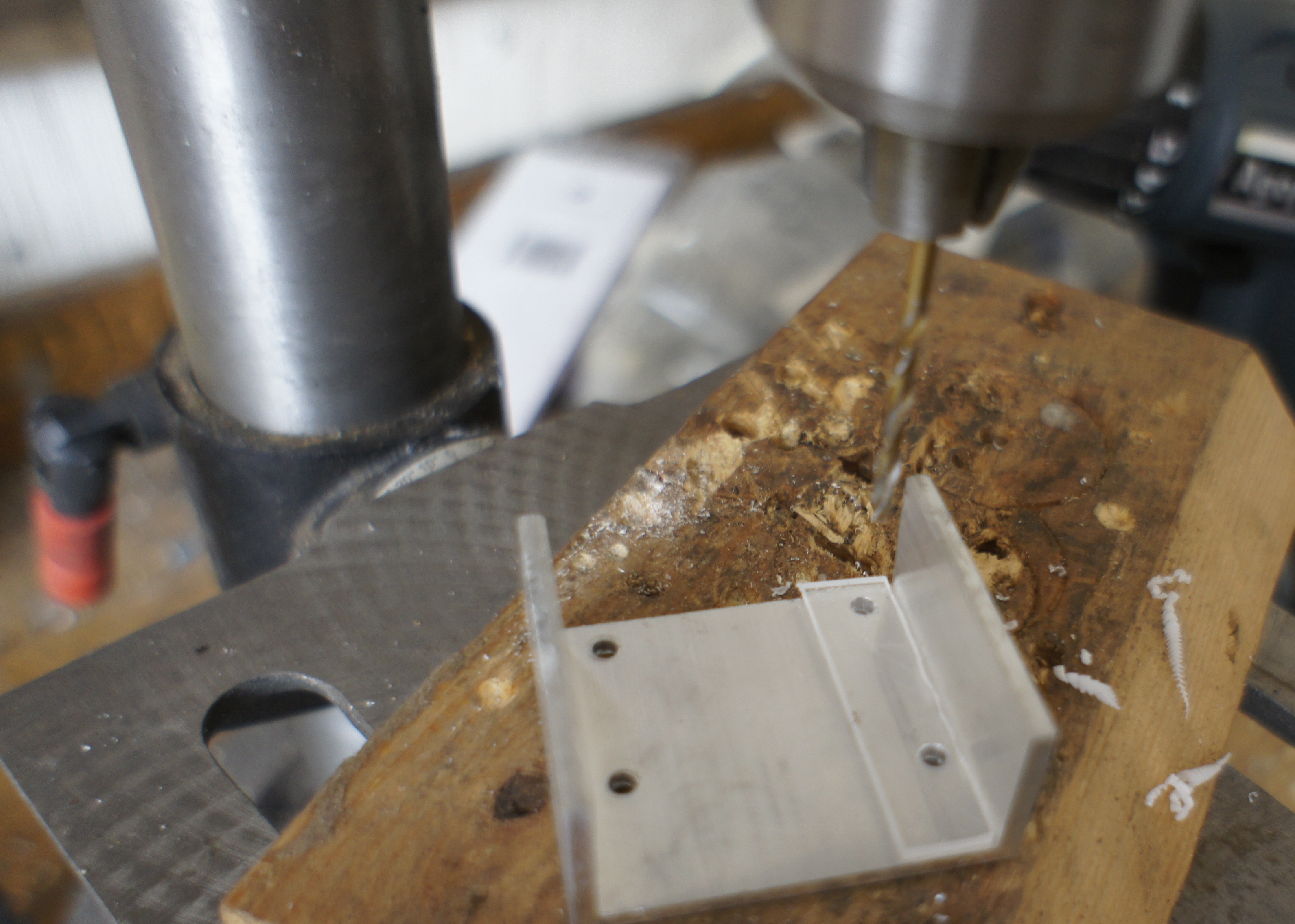
When you put the two small pieces inside the bottom-U-profile where they should come, it is easy to see trough the clear acrylic where the holes should come.
Drill this holes with a 3 mm sharp-steel-drillbit and don't push to hard or the material might break. Remove the drilled material from the drill bit often. It might be molten onto the drill, but it should be easy to remove.
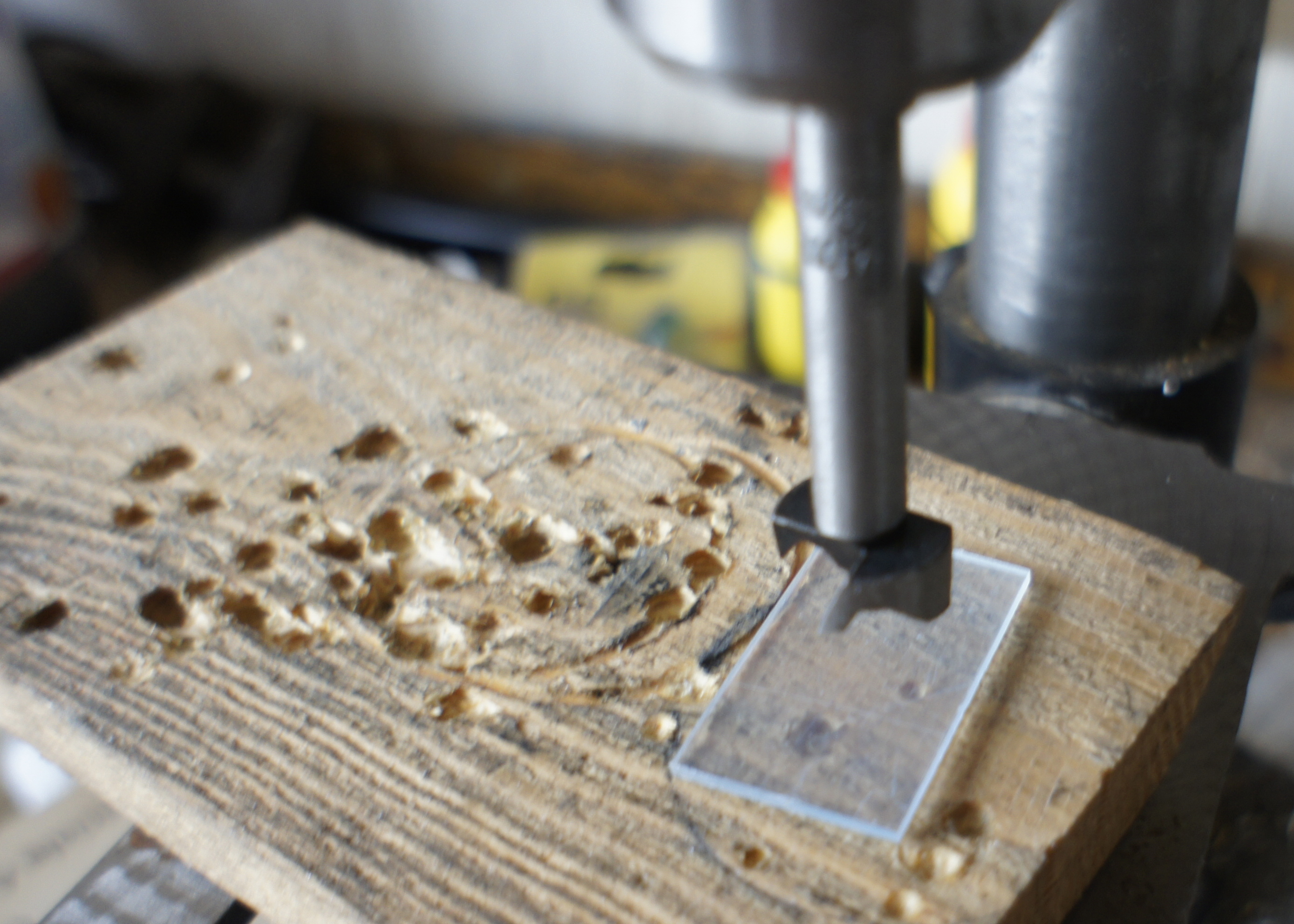
In the big piece we need to drill a big hole, the size of the battery (20 mm in my case). I had a nice drill for that. Still I had to go slow and removed the scrapings very often.
The cover
To cover the battery, I used a thin sheet of plastic. With a small screwdriver I pierced four holes for the bolts and one more for the positive lead to go trough. This fifth hole must be next to the PCB and next to the battery.
The On/off Switch
Where to put it
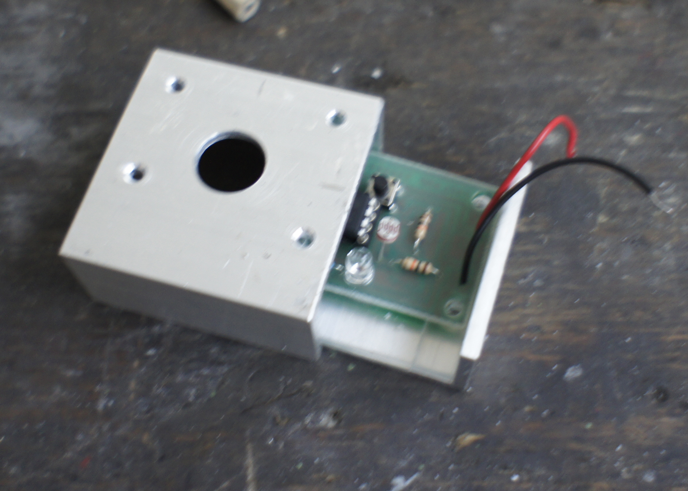
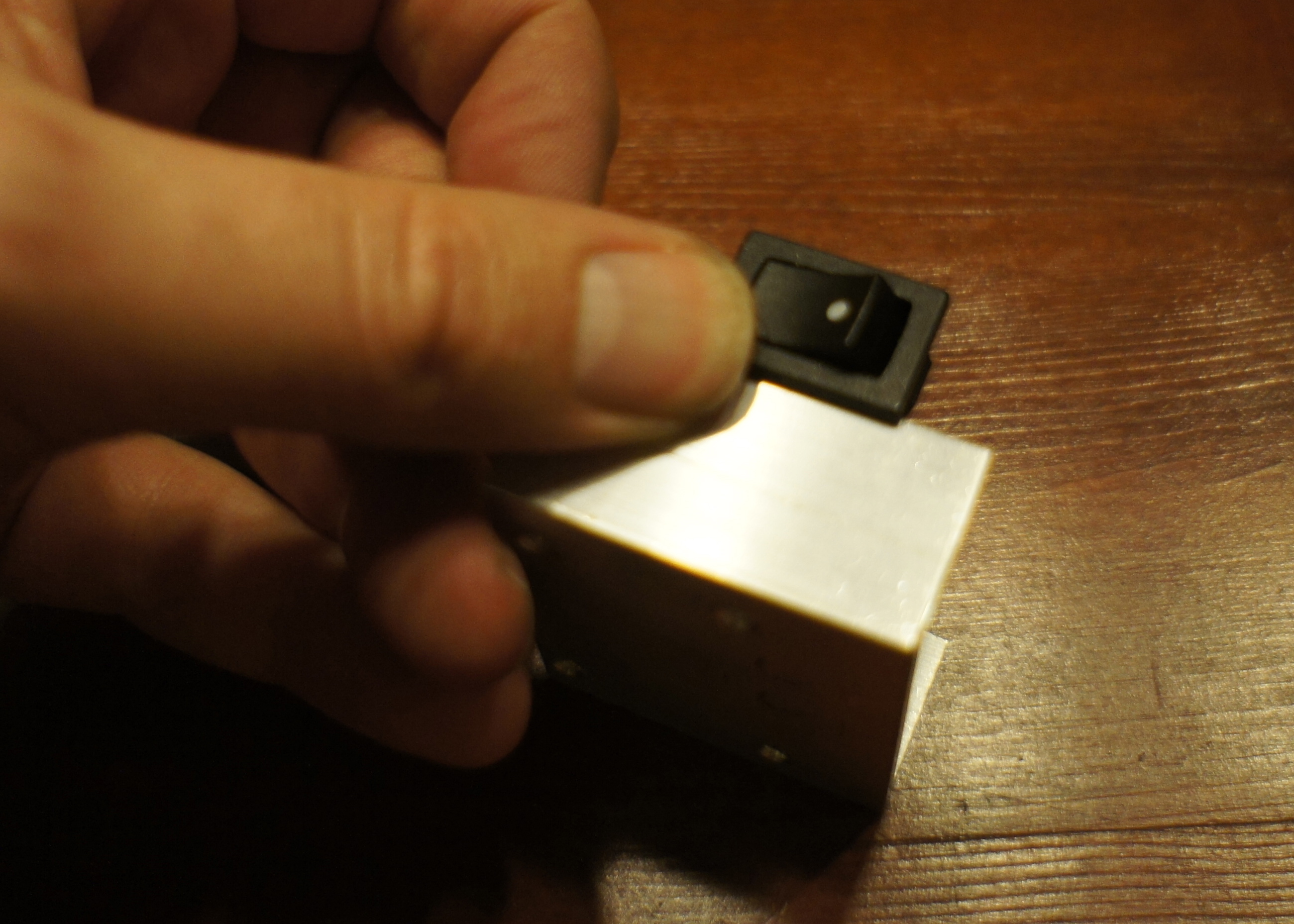
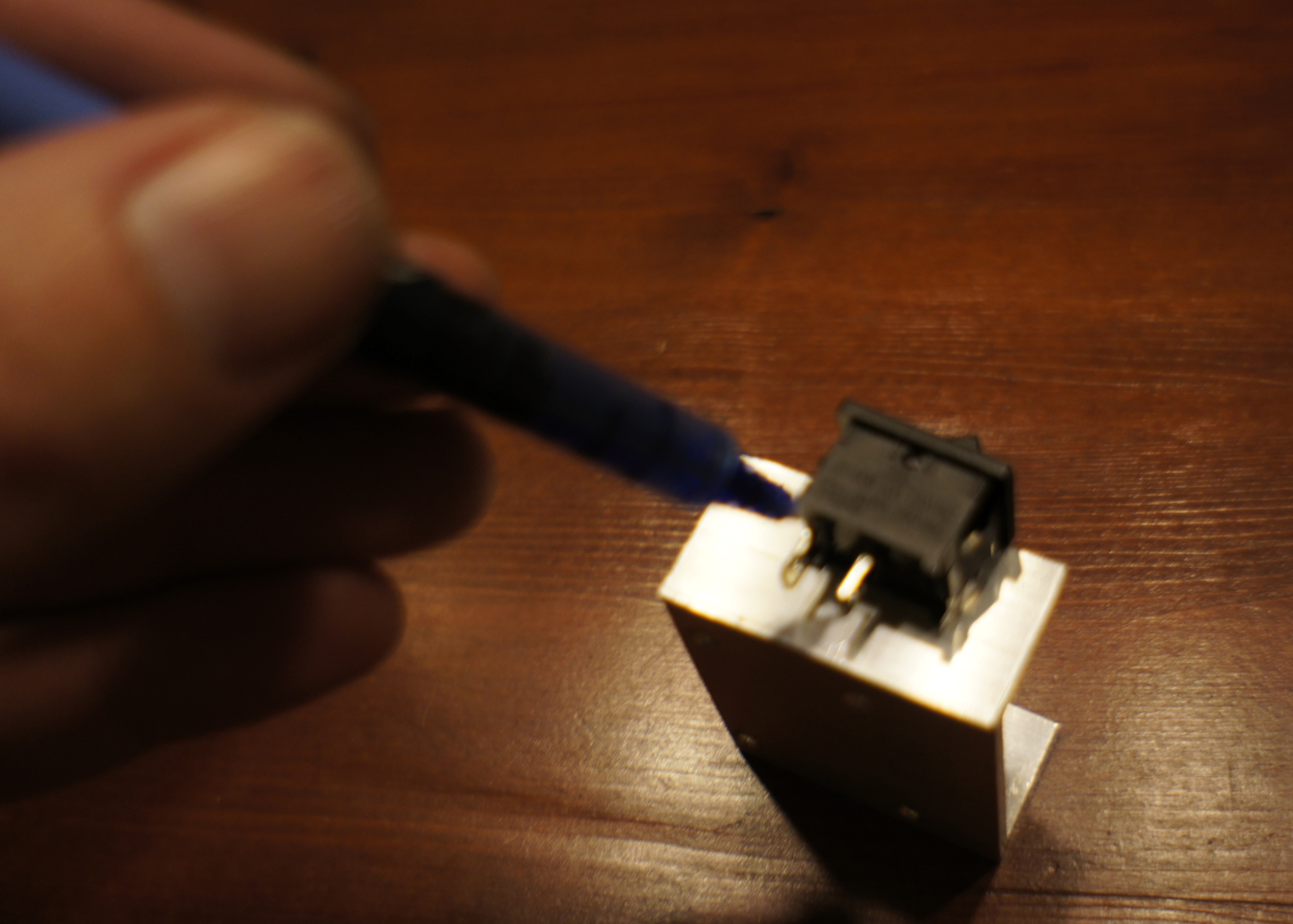
Now that we can put in the battery-compartment with the PCB on top, we can figure out where to put the on/off switch. It just fits on the side, above the PCB.
Making the hole
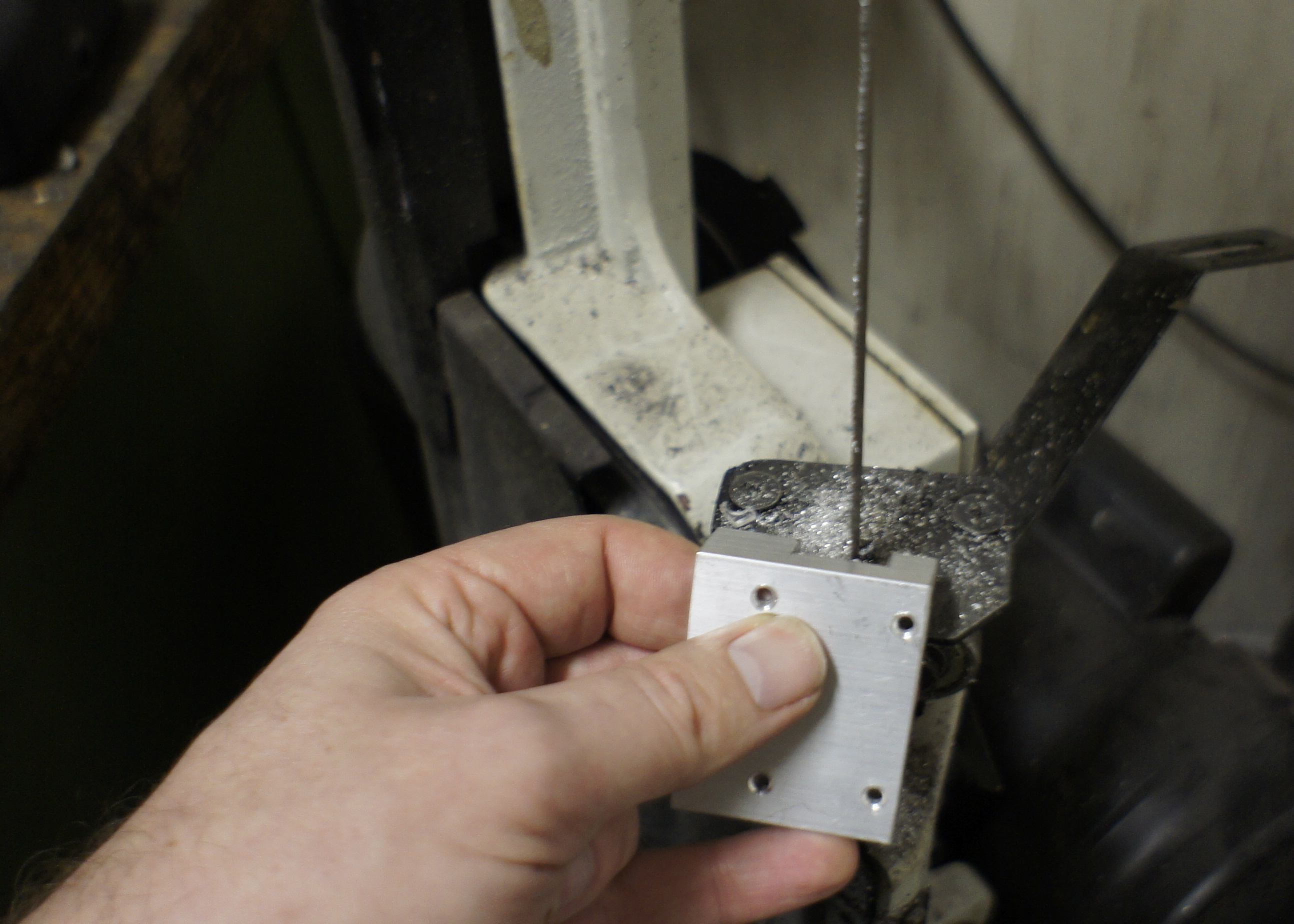
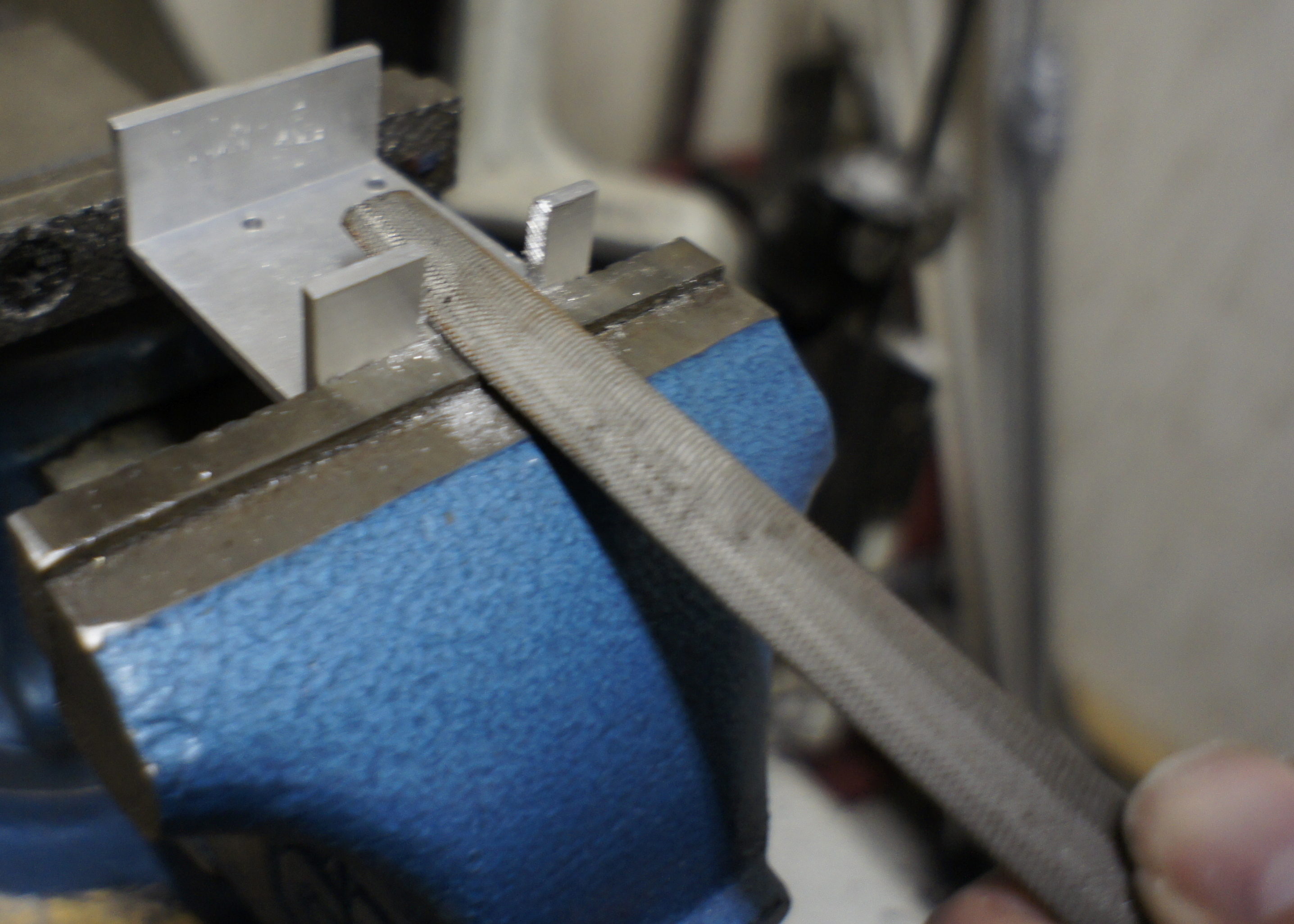
First I measure where the button comes and draw this on the aluminum with a sharpy. I saw into the aluminum several cuts approximately 2mm from each other. With a plier I break out the little 2mm peaces. I make the hole smaller than it should be. Now I put the bottom-piece in the vise with the the sharpy-line just showing. With a vile I make the hole the correct size. It can never get to big because the vise is protecting the rest of het profile.
The Push-button
Making the pushbutton
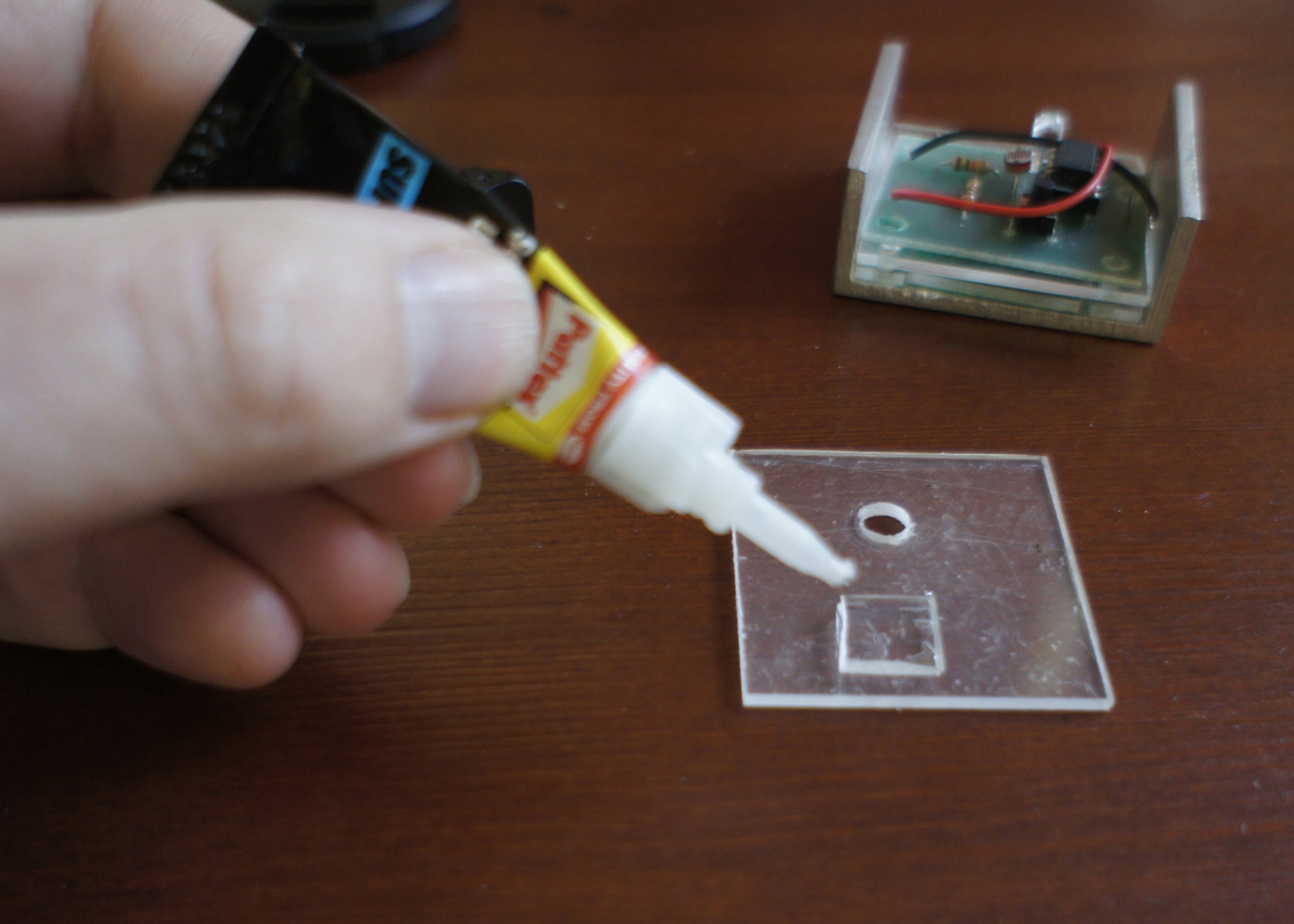
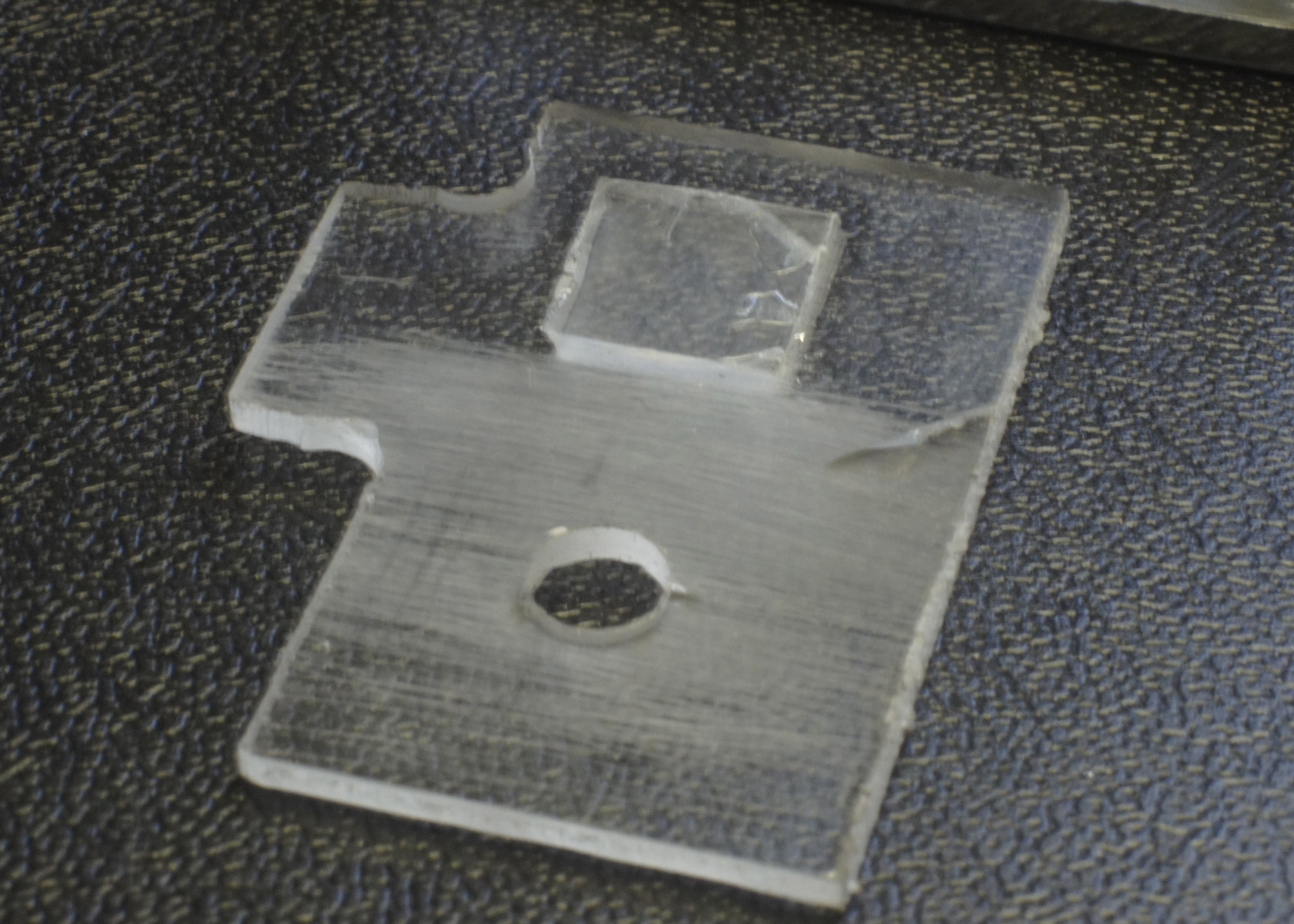
The pushbutton has tree functions.
With some sanding-paper I made the under-side of the acrylic opaque, for the LED to be better visible when it lights up.
The pushbutton has tree functions.
- a pushbutton
- a window to let light reach the light-sensor
- a screen to show the LED
With some sanding-paper I made the under-side of the acrylic opaque, for the LED to be better visible when it lights up.
The Last Soldering

Finishing touches on the PCB
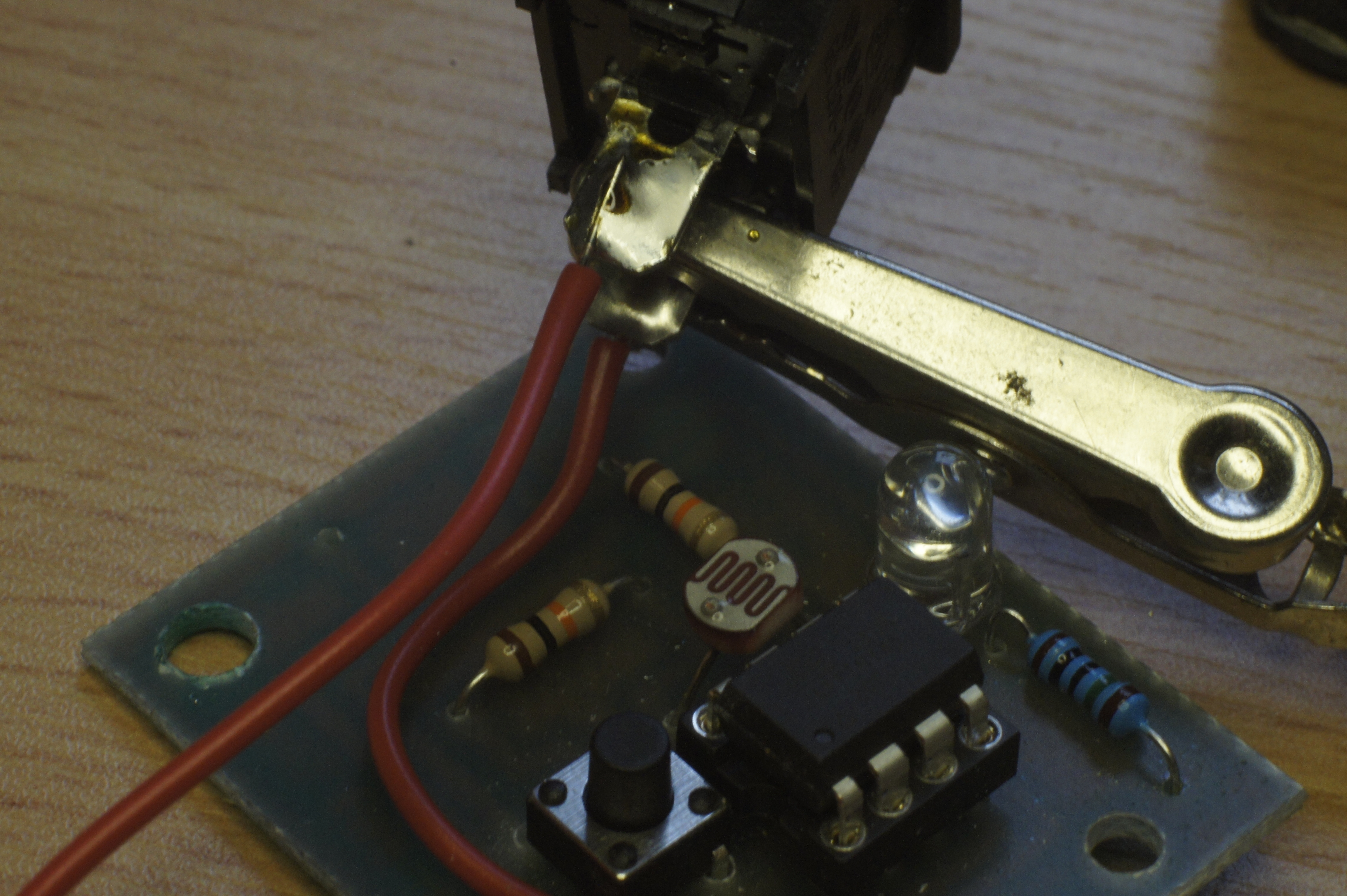
I remove the wires I temporarily used to hot-wire the on/off switch and the wires I temporarily used to power the PCB.
Now I solder one wire from the PCB to the on/off switch. (not the wire going to the power on the PCB, but the wire going to the IC) On the other connection on the on/off switch I just solder a wire. (it will go to the + of the battery later on)
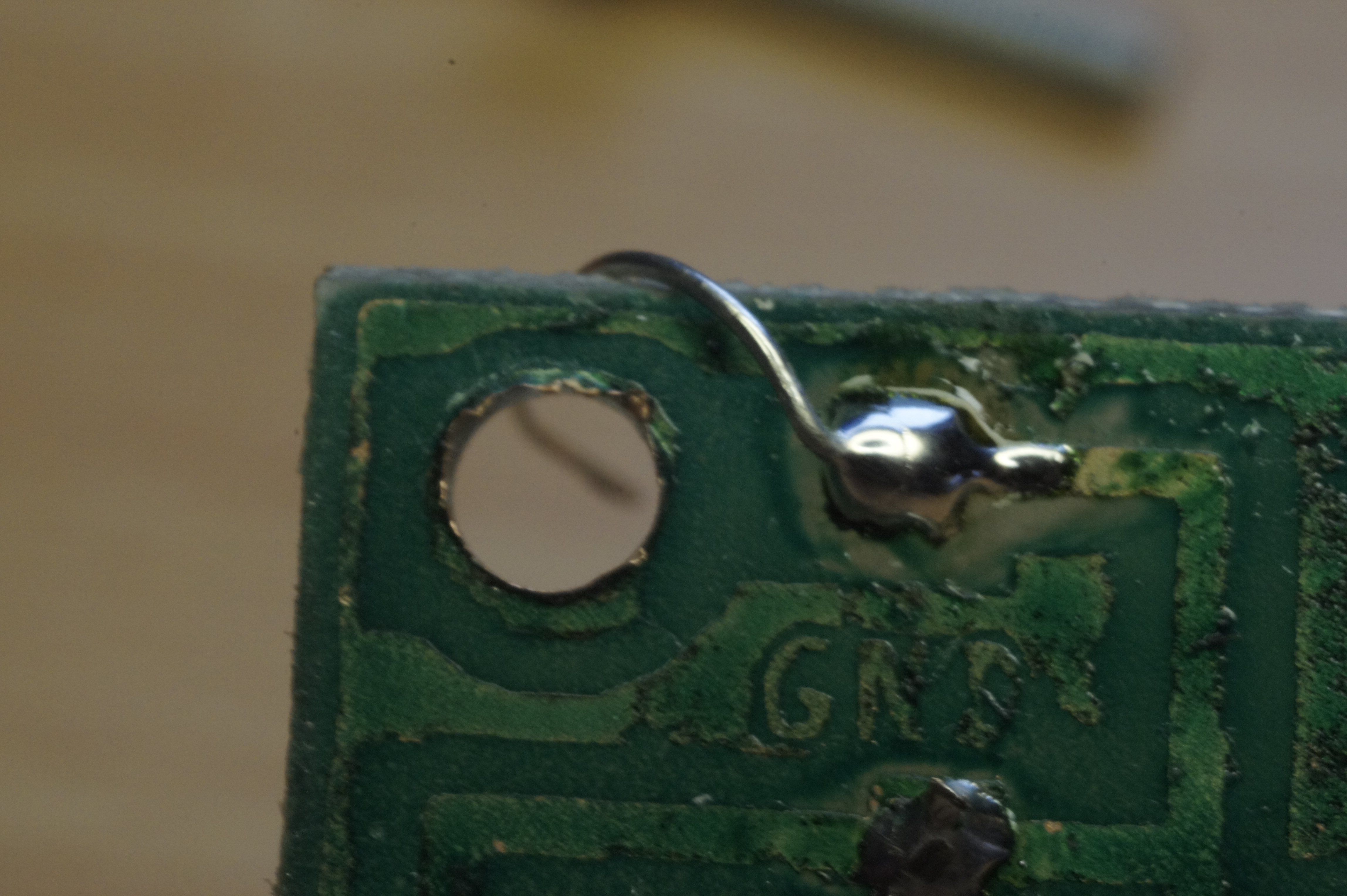
On the GND (ground) connection on the PCB, I just solder a piece of not-isolated wire. I push this wire along the side to the other side of the PCB and around the hole for the bolt.
Putting It All Together




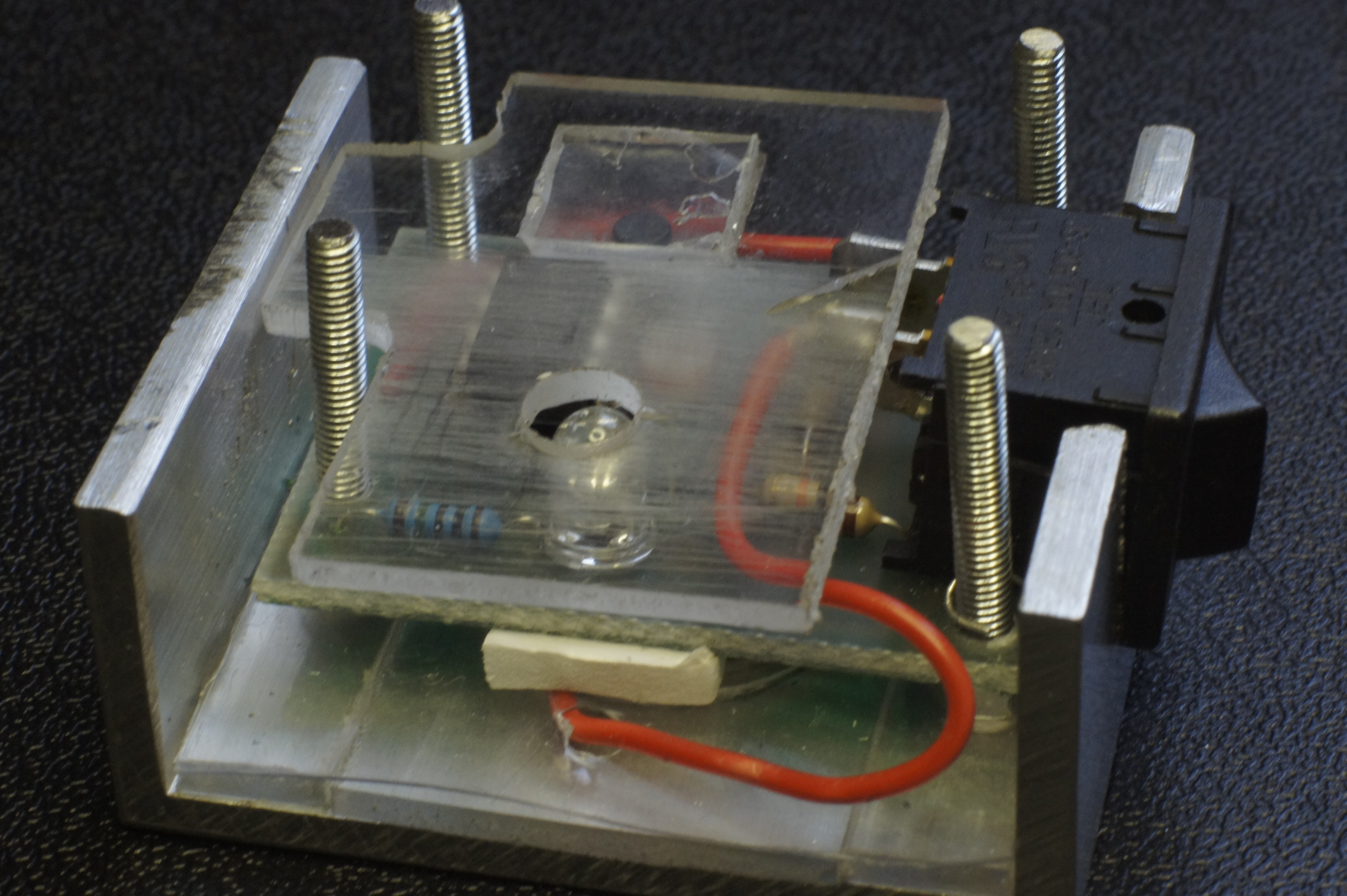
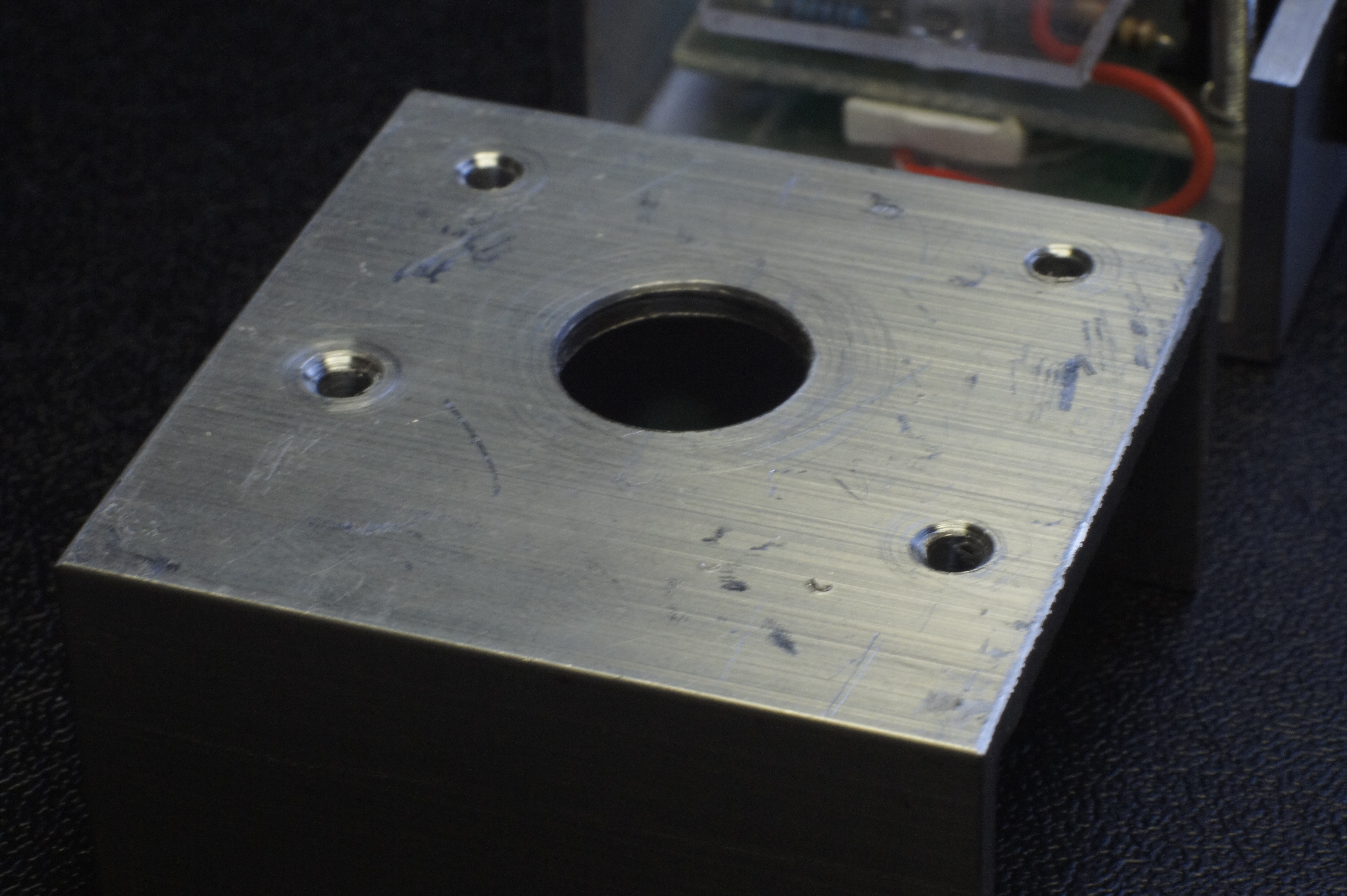
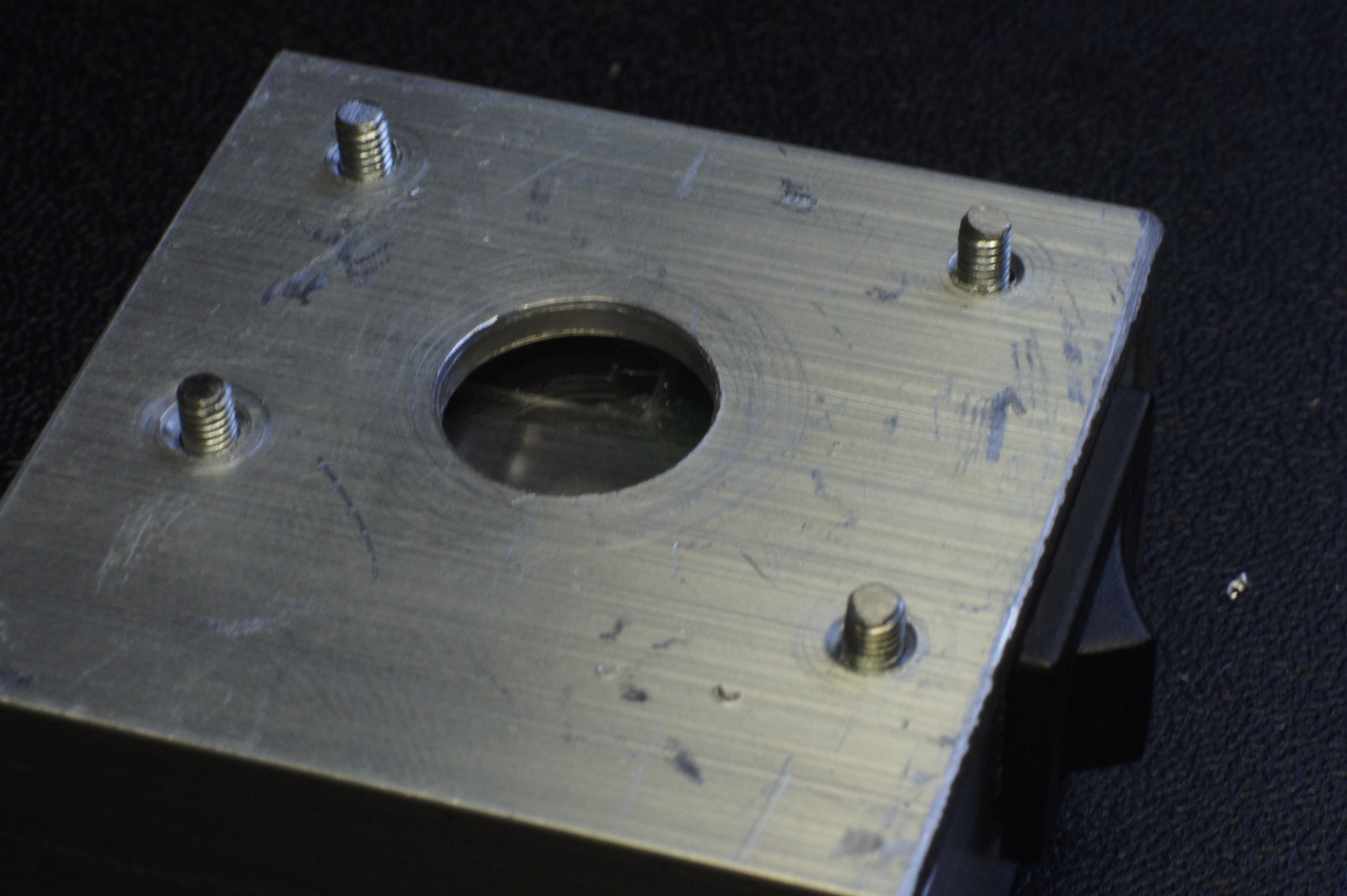
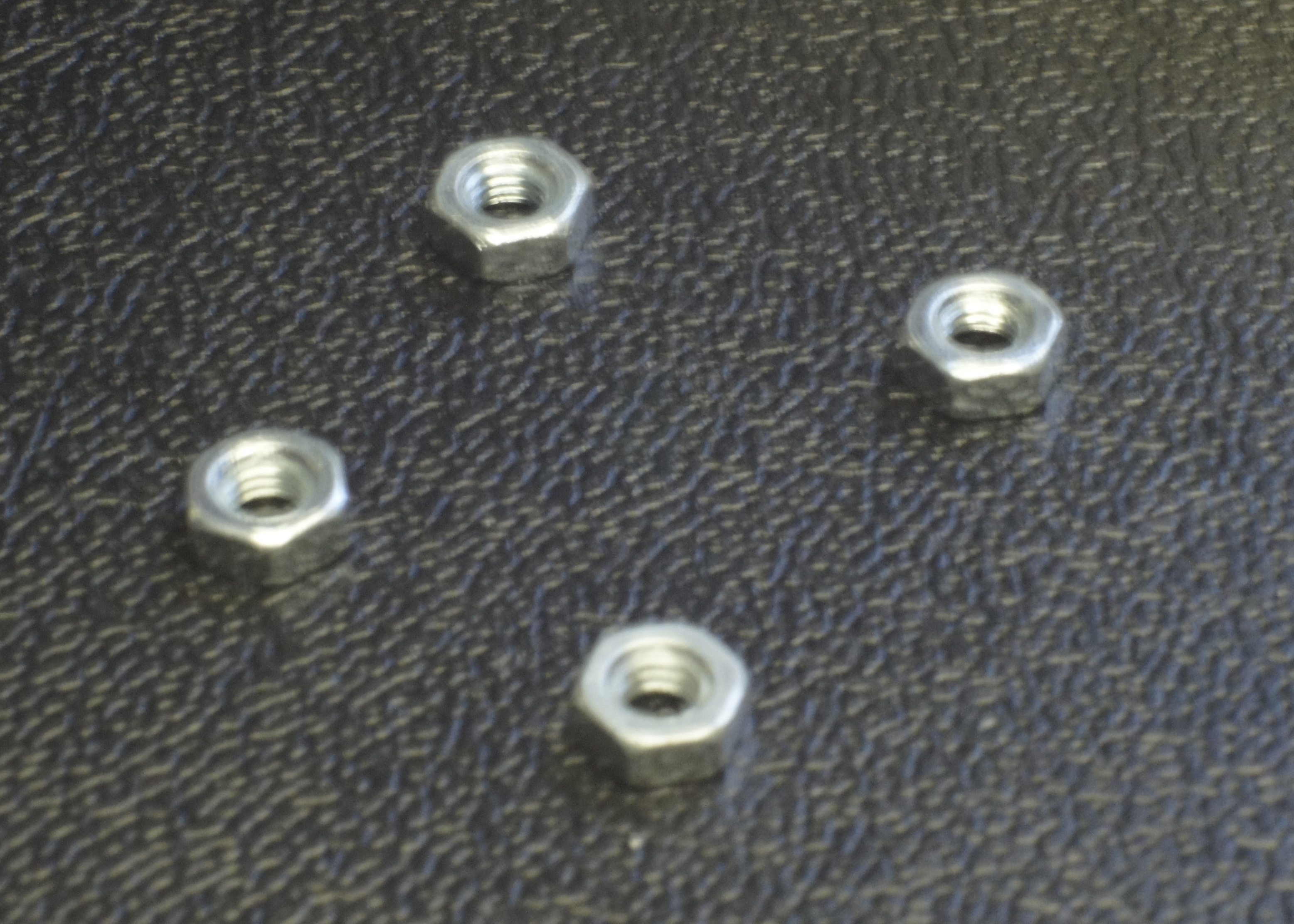
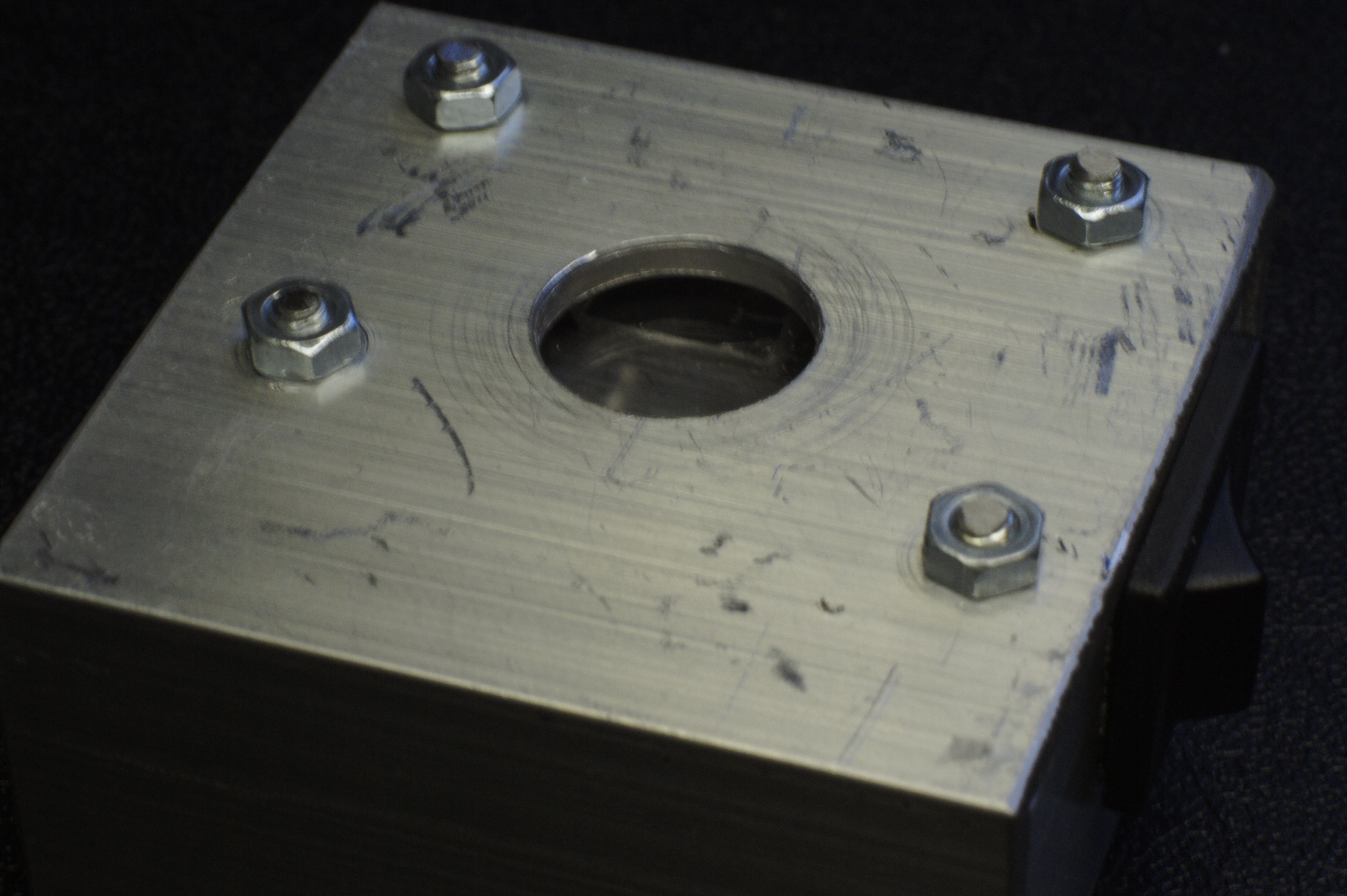
Putting it all together
Finally it is time to put everything together:
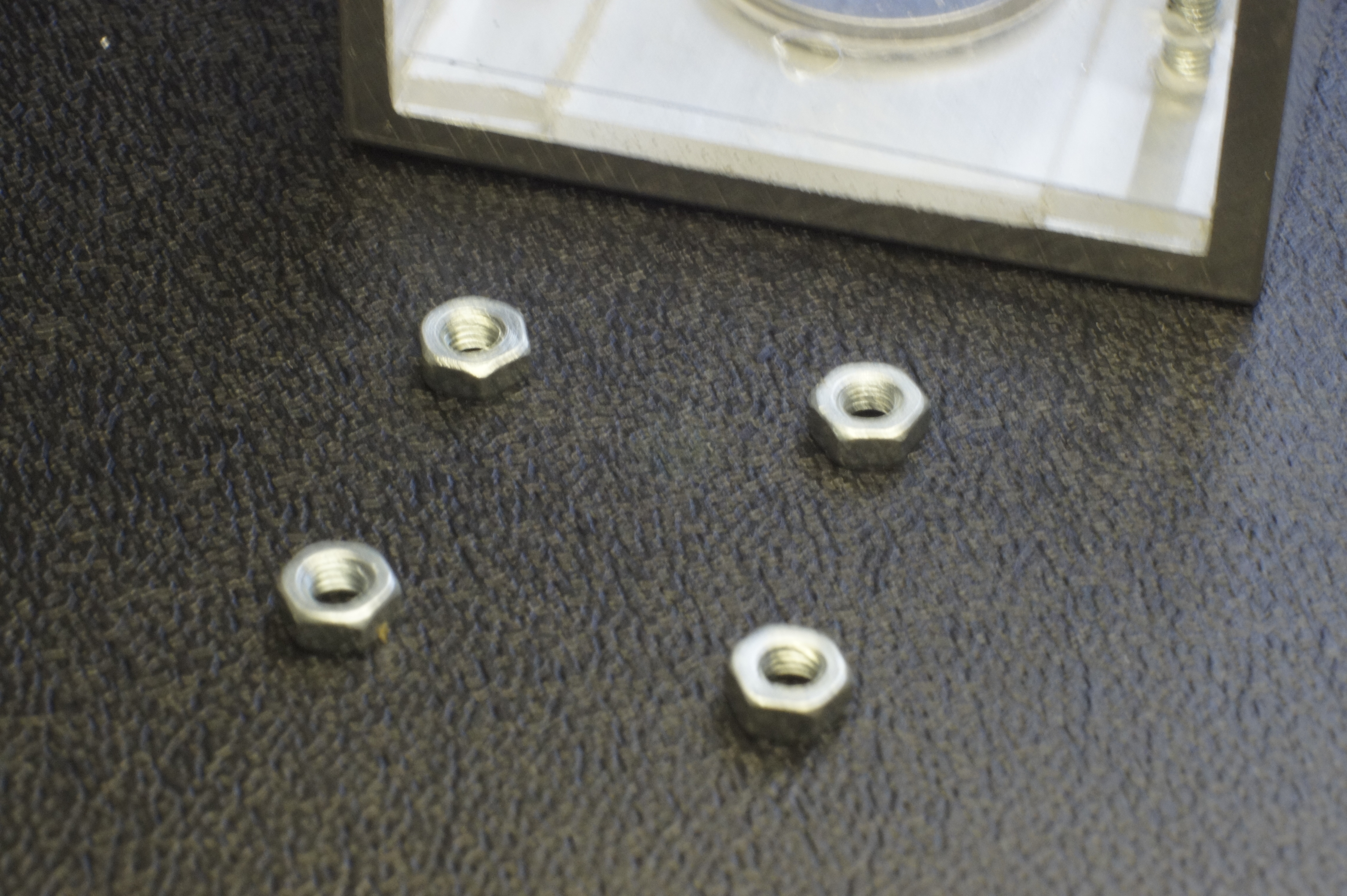
(in my line-up picture I forgot the push-button acrylic)
Finally it is time to put everything together:
(in my line-up picture I forgot the push-button acrylic)
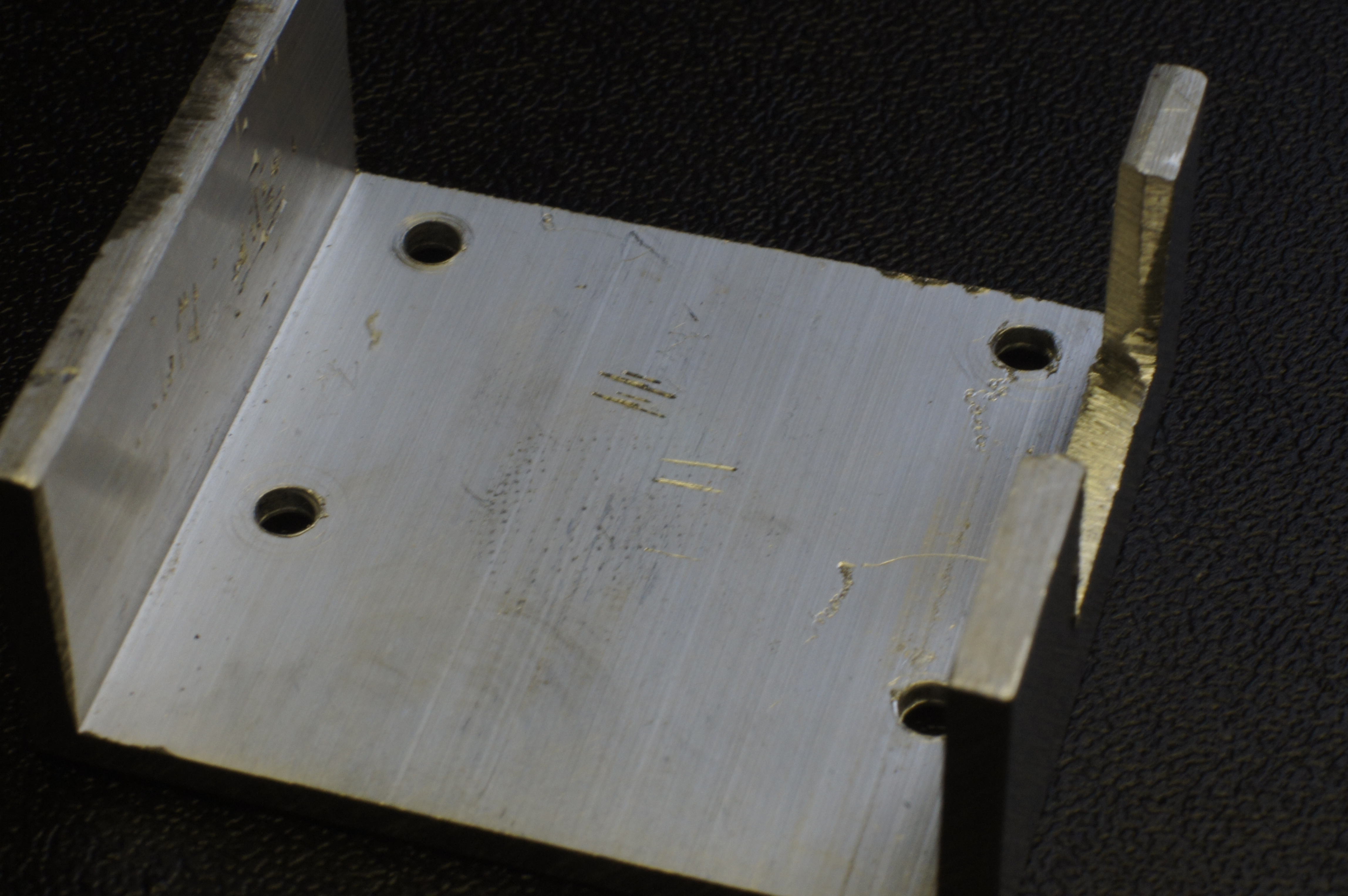
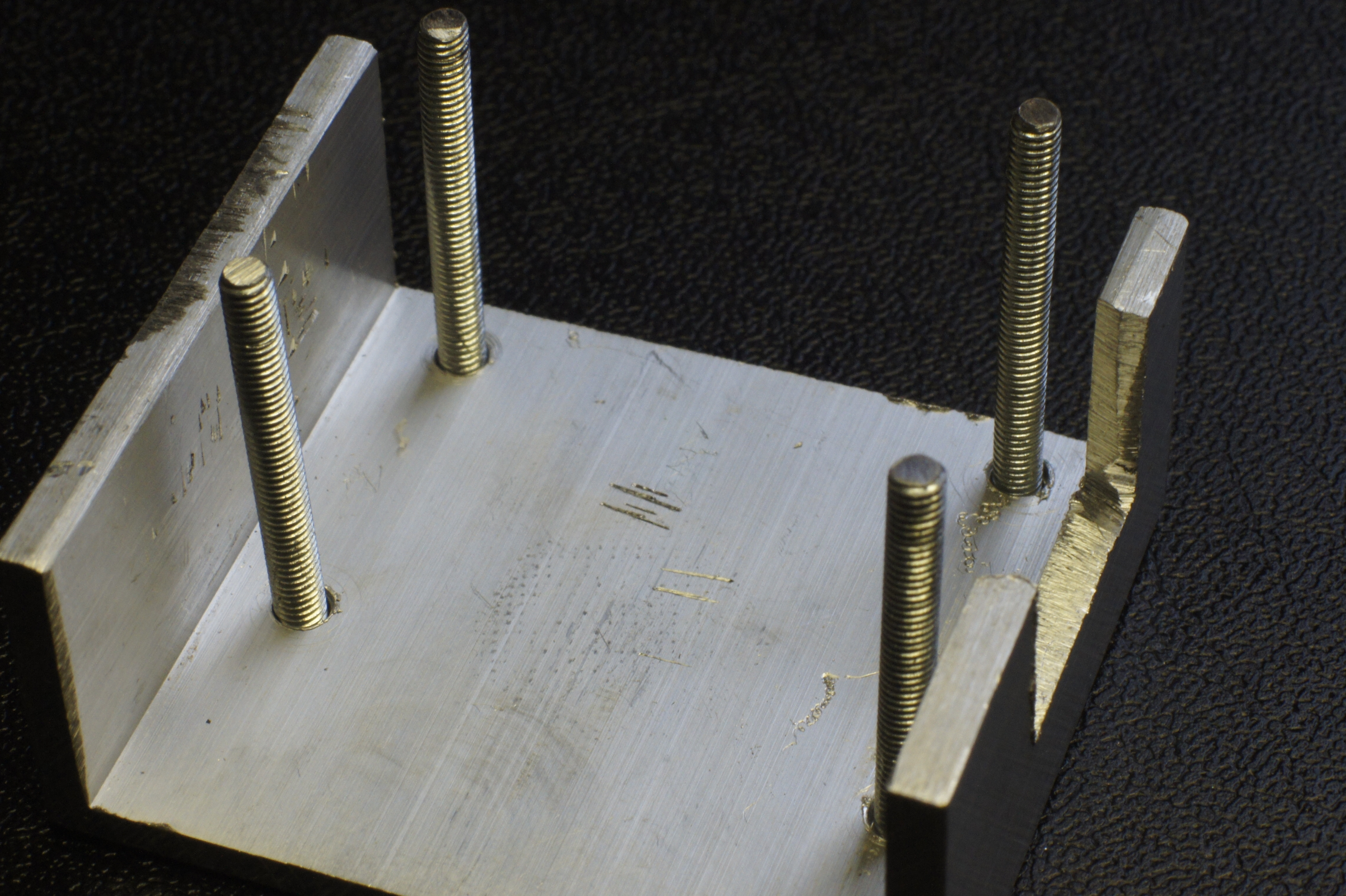
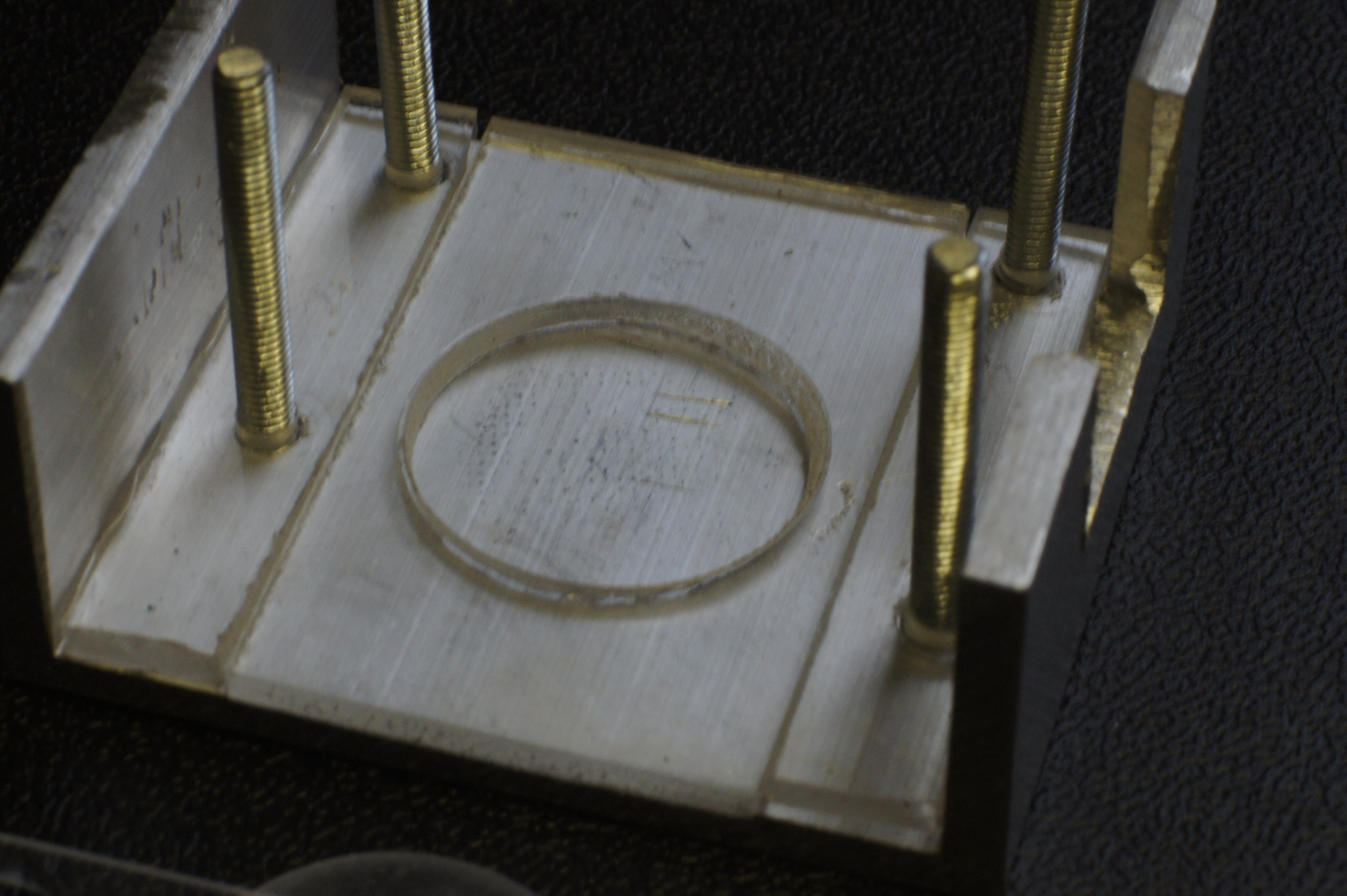
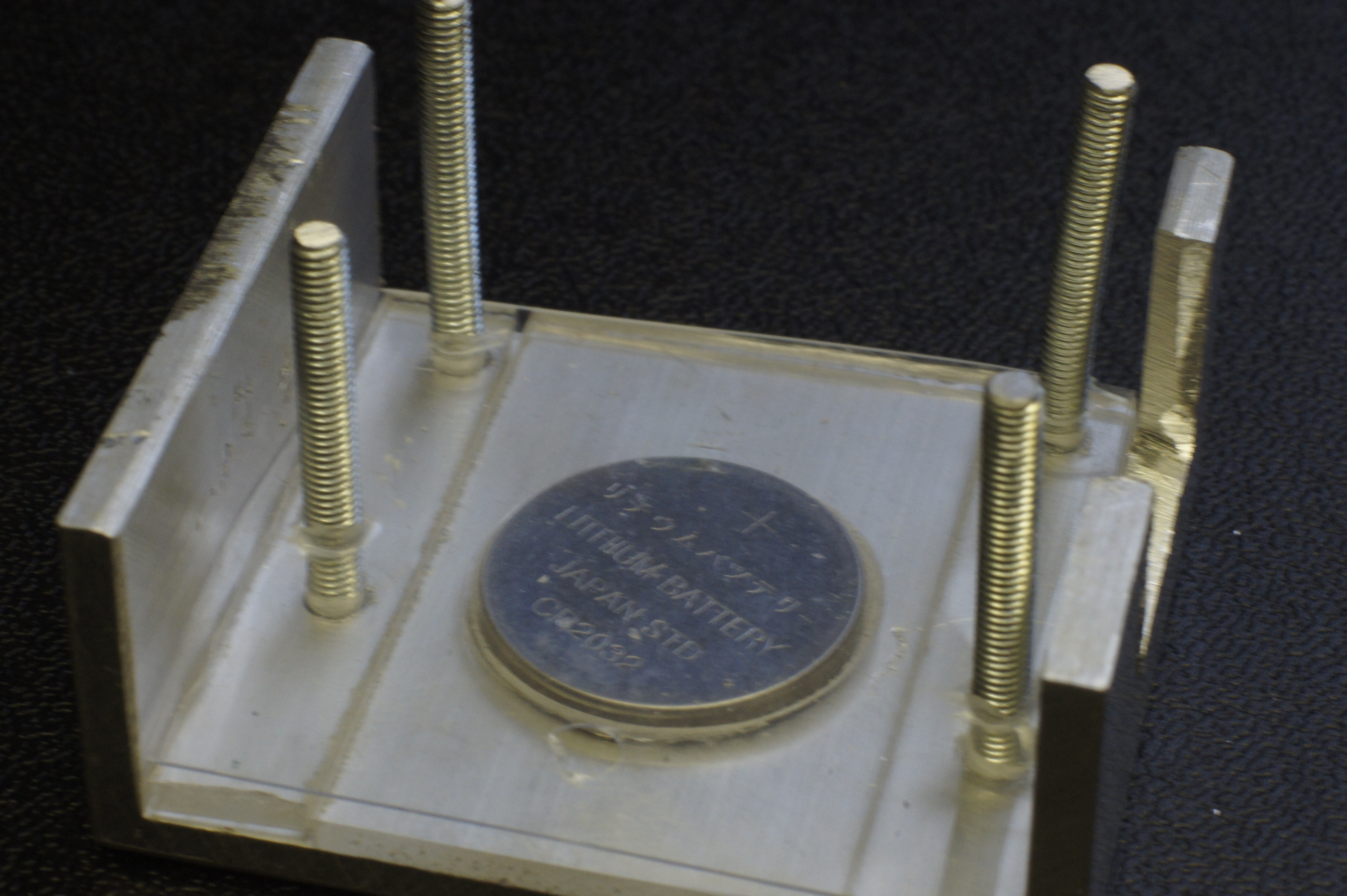
- Start with het bottom U-profile
- Put in the four bolts
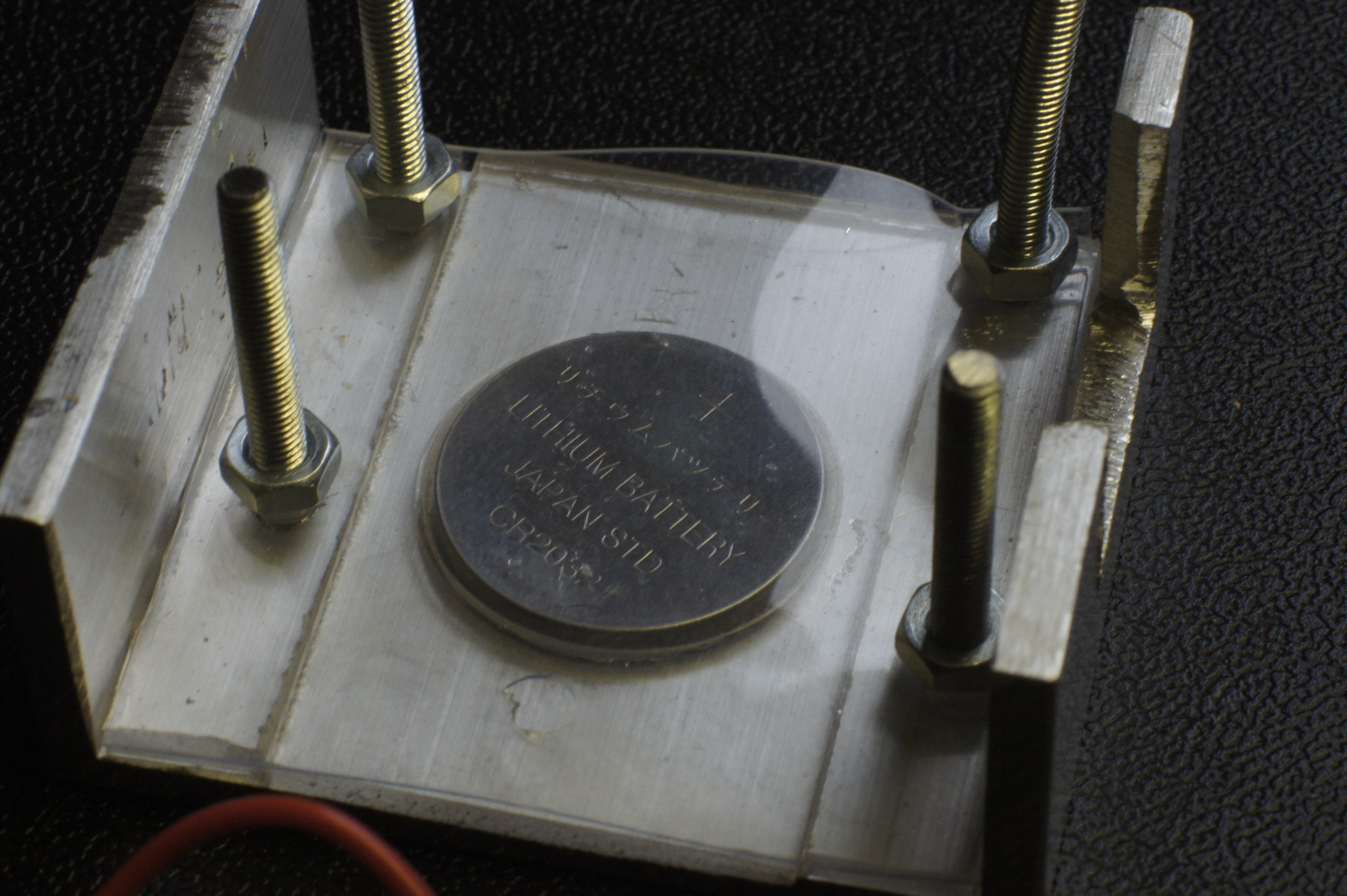
- Add the two acrylic strips and the piece with the hole for the battery in the middle.
- Place the battery with the - (minus) of the battery down, touching the bear aluminum.
- Ad the thin sheet of plastic.
- Fasten with four nuts.
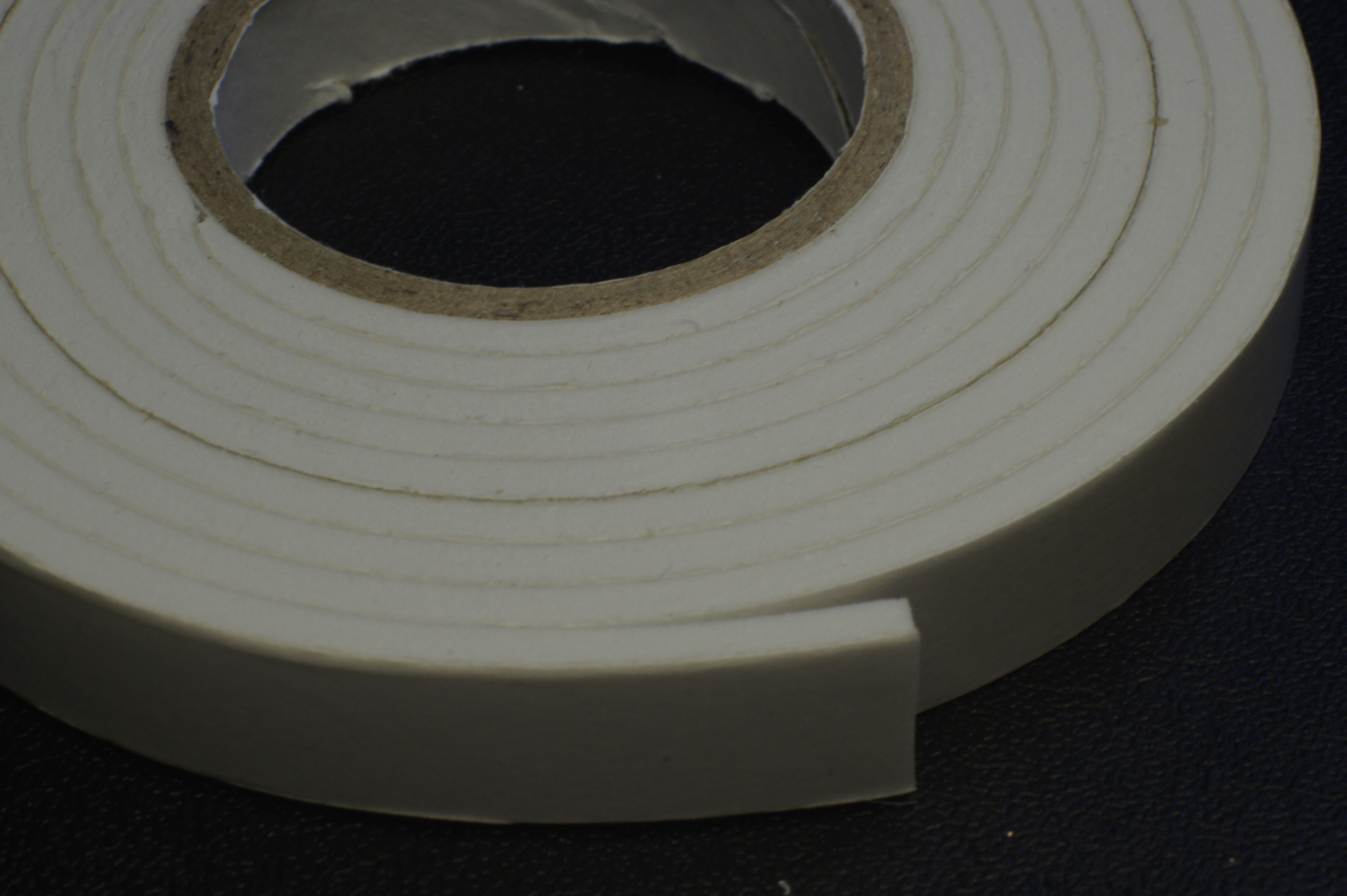
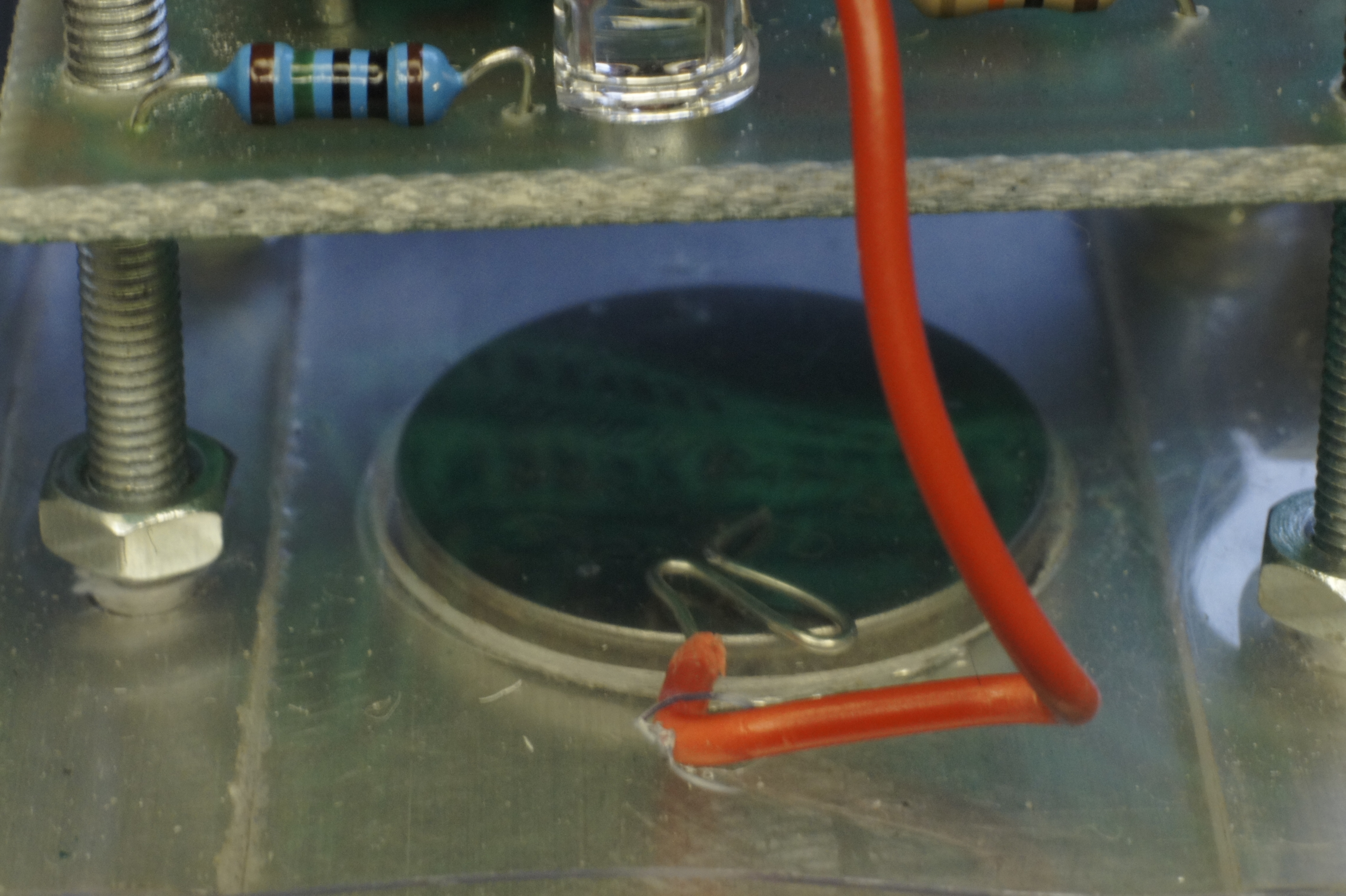
- Put a piece of foam-tape on the thin sheet of plastic where the side of the battery is underneath it.
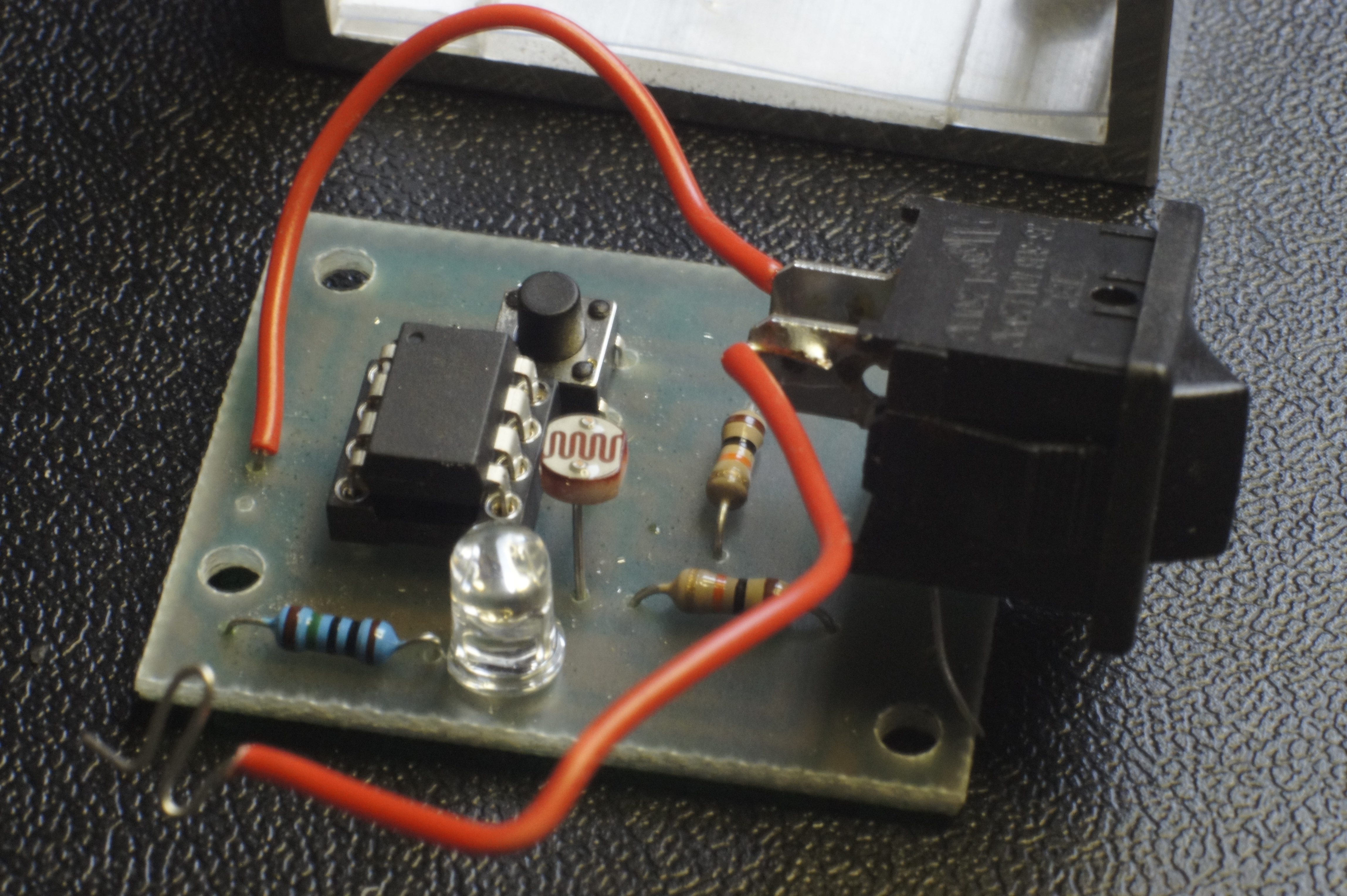
- Put the PCB halfway on it.
- Strip the end of the wire coming from the on/off button.
- Bend the wire in a zig-zag and put it trough the fifth hole in the plastic sheet to touch the top (+) of the battery (under the piece of foam-tape)
- Push the PCB all the way down.
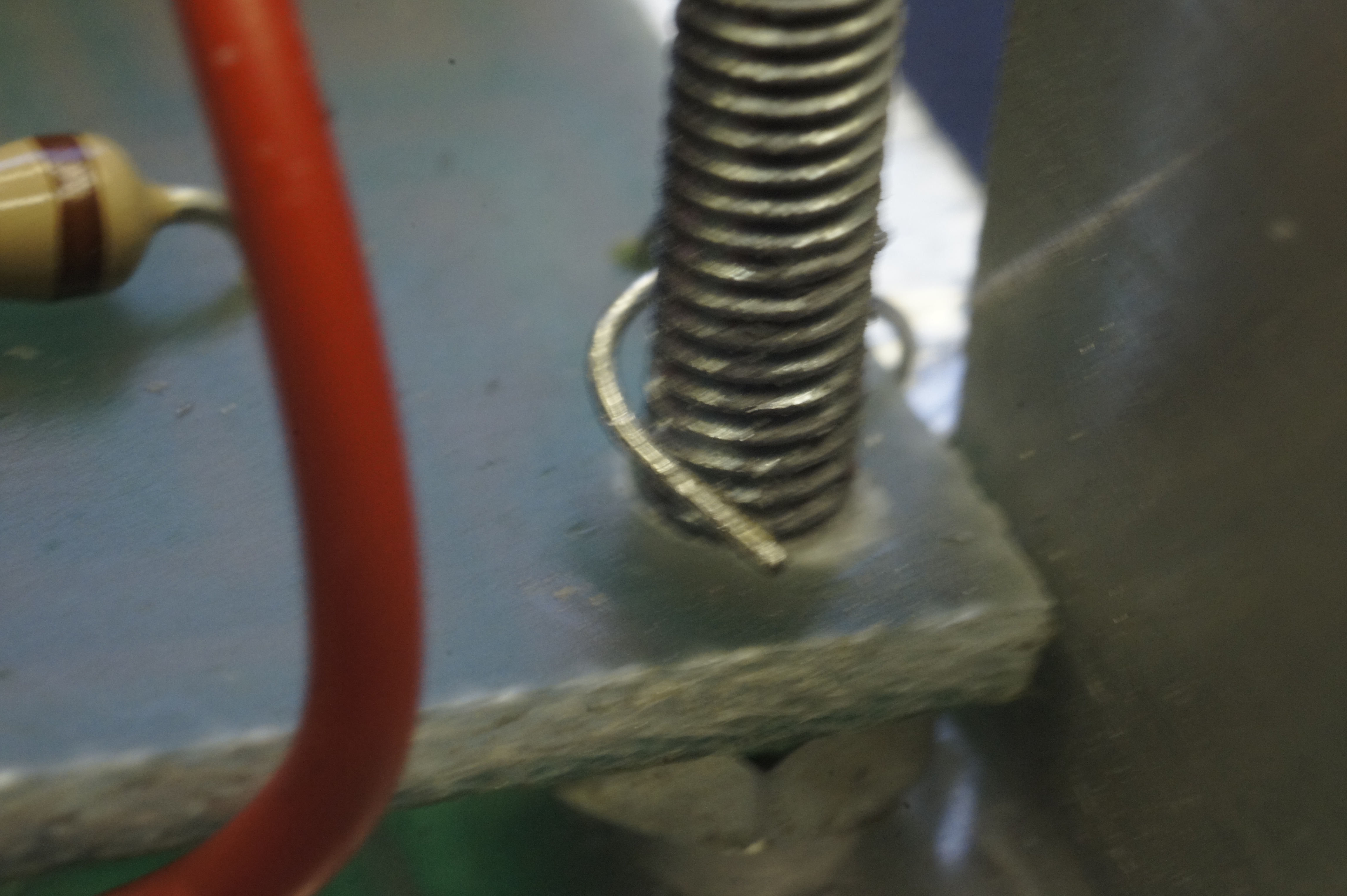
- Make sure that the bear wire coming from the GND on the PCB, touches the side of the housing and is wrapped around the bolt, to make a good ground-contact.
- Put the on/off button in place. (make sure all the wires aren't in the way of something like a button or sensor)
- Turn it on and see if it works... ...Yes!!!
- Add the push-button acrylic. (it just lays on top of the PCB)
- Put the top-enclosure on it.
- Just four more nuts.
How Does It Work?
How to play?
Flashlight tag
Each player gets one (thing we just made) on his person and a flashlight. You go somewhere where it is dark. (A dark sports field or woods or something where they can safely run around in the dark)
When you are in the dark, everybody turns on his device.
When the game starts the players try to shine their flashlight on the hole in the device of an other player. If it is a hit, the LED will light up for 3 seconds and the device will not record other hits in this 3 seconds. When the time is up, everybody comes to the leader. (be sure that you don't turn off the device and you stay in the darkness)
If you push the window (and by that the push-button) the device will flash the LED as many times as that person was hit.
The person with the least hits wins. The person with the most hits had probably the most fun.
Now you can turn off the device and it will reset itself. If you don't turn it of it will continue counting on top of the score you already had.
Who has the best
Now I've made this, I come up with more uses. If you ever been on a camp with 8 year old boys (or older) you probably noticed that they can't help showing of. One of the things they love to show of is the brightness of their flashlight. The question now is: Who has the brightest and by that, best flashlight?
Now it is easy to figure this out once and for all!
You put the flashlight-tag devices in a field: one at 2,5 m, the next at 5, then 10, 15, 20 m and so on. (depending on how many you've made)
If your light beam can reach them with enough power, they will light up, so now it is easy to see how far you come.
More uses?
Can you come up with more games or other uses for this device? Let me know in the comments.
Have fun!
Finished?

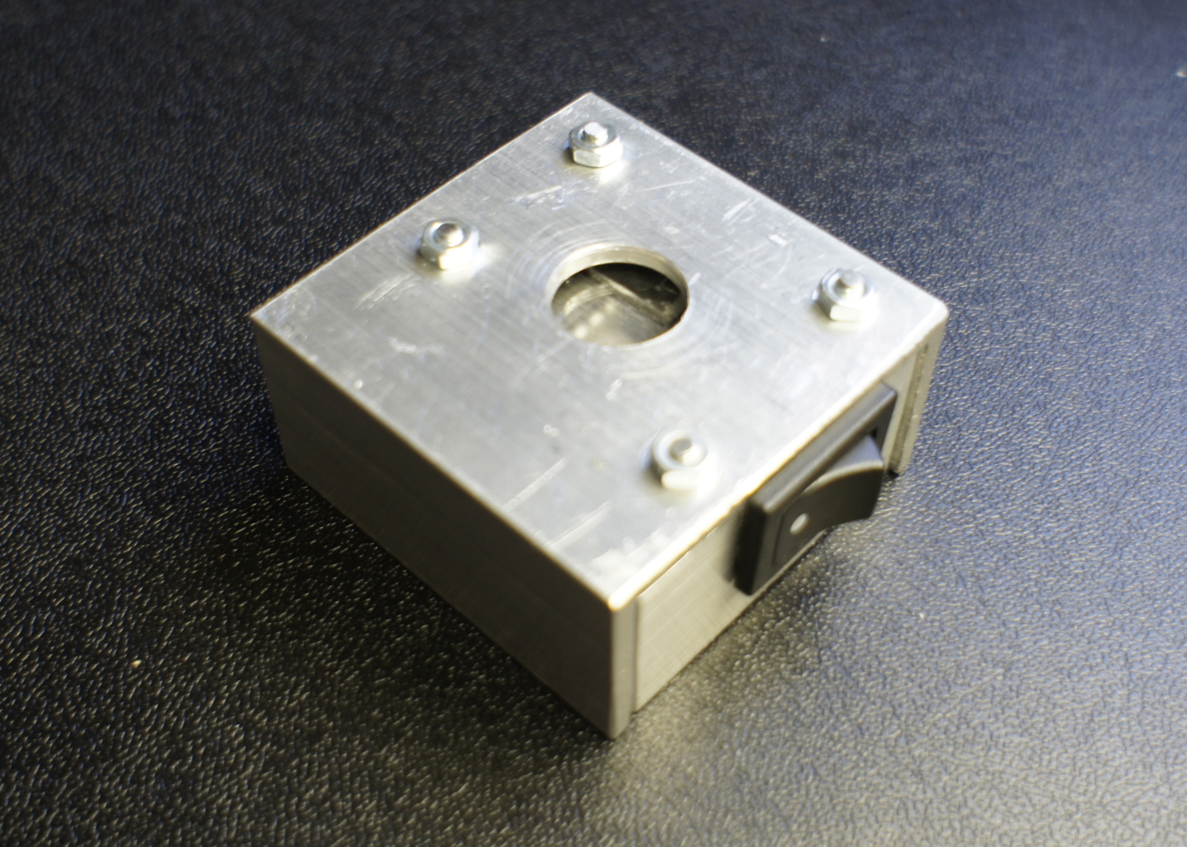
It works, it feels solid and play-proof.
So am I finished with this project? Not really. I have to find a way for the kids to carry this device on their upper-arm I think. Something with velcro might work. Any ideas?
And I will have to make much more of these things, because it is not much fun to play flashlight-tag all by yourself.
How do you film a device that works in the dark? Not really much to see here.