Flashing EACHEN WiFi Smart Touch Switch With Tasmota
by Bert_Wright in Circuits > Remote Control
2657 Views, 3 Favorites, 0 Comments
Flashing EACHEN WiFi Smart Touch Switch With Tasmota

So I decided to make this Instructable for anyone else out there that has been wondering if this is possible.
Components Needed
Serial-to-USB Adapter
Tasmota Firmware Binary downloadable
Soldering Tools
Jumper wires
Flashing Tool downloadable I used Tasmota PyFlasher
Download All Software and Install Flashing Tool
You can download the Tasmota binary file from this link: Tasmota releases
Here is a link for one of many Flashing tools: Pyflasher
Once all is downloaded install your flashing tool in the desired location.
Soldering

To flash the Light switch you need 5 pins from the ESP8285 Chipset. You need the RX, TX, VCC, Gnd and GPIO 0.
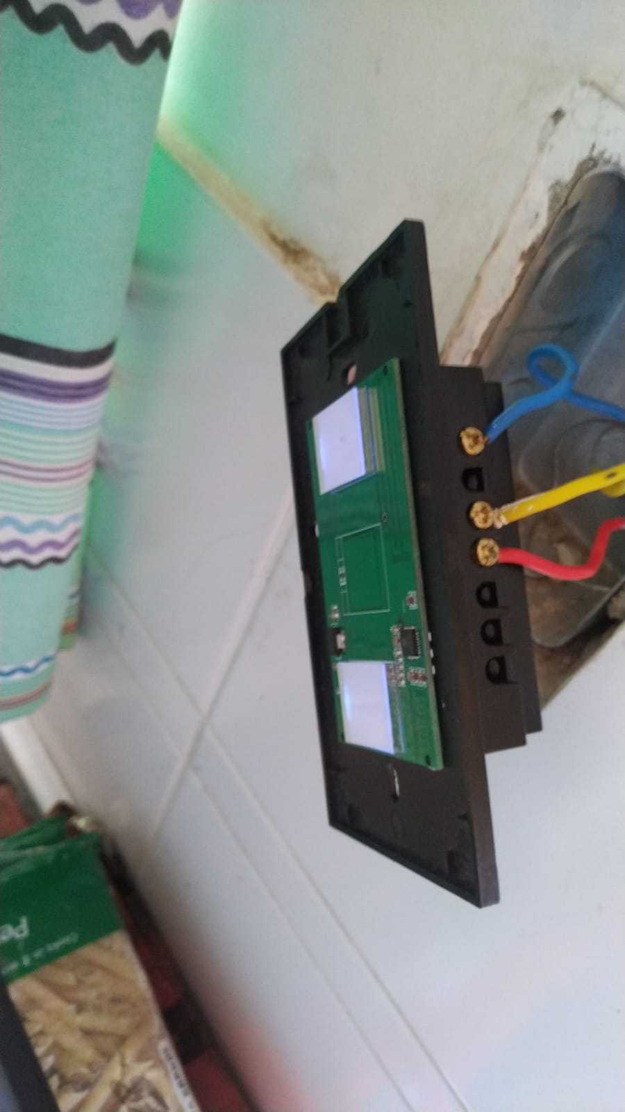
You going to need to take the light switch apart, until you have just the front PCB(the one with the buttons on)
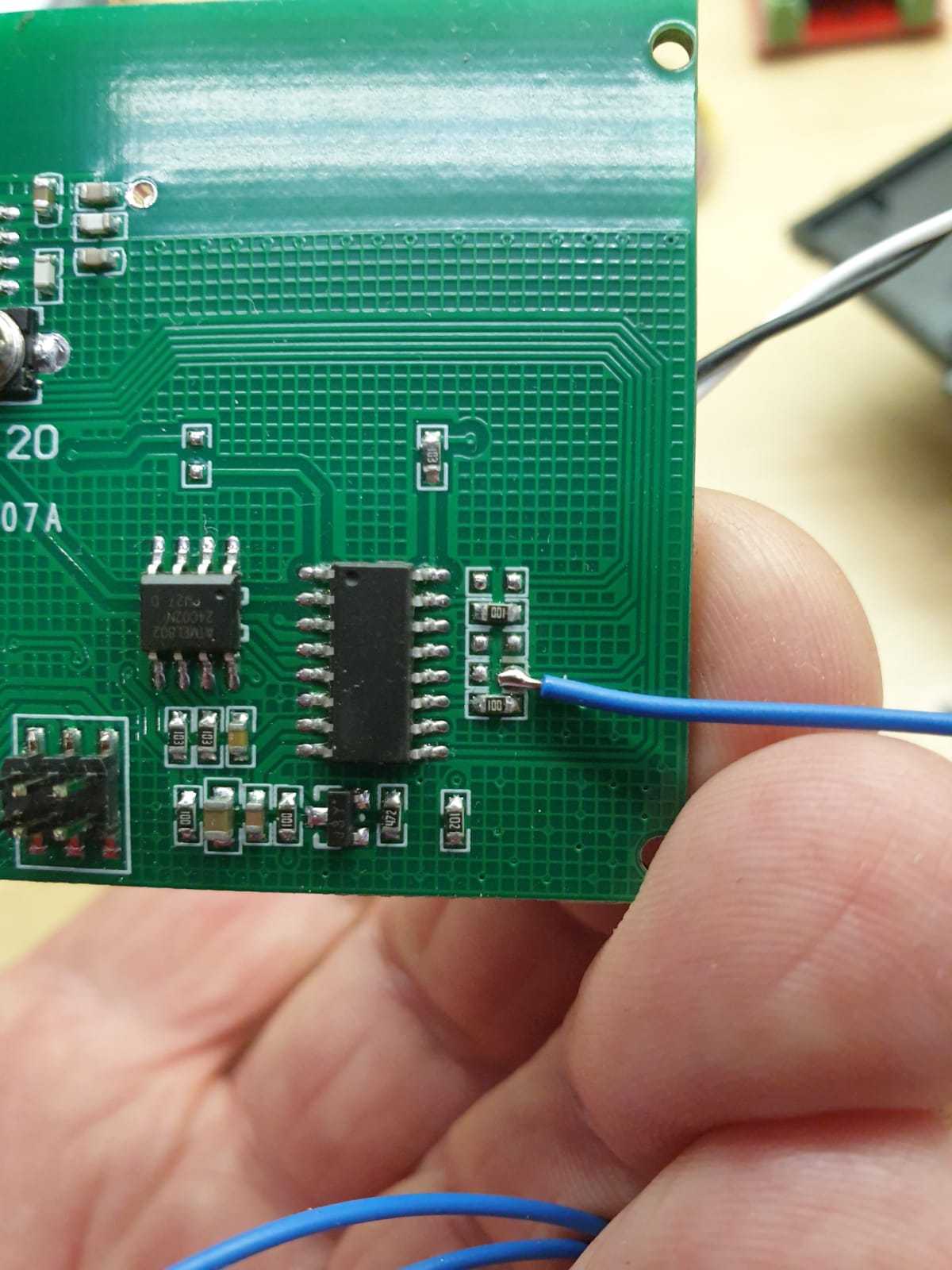
As you can see in the picture you going to need to solder a wire about 10cm long onto this location which is where GPIO 0 routes to. you are going to need to short this pin to ground at a later stage.
Making RX and TX Accessible

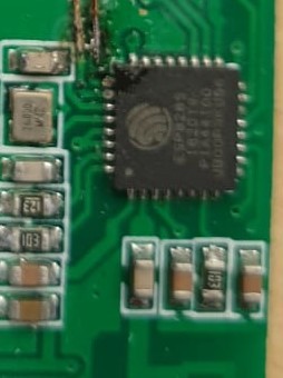
You are going to have to scratch the covering on the pcb to make the tracks accessible to be able to solder two small wires on like in the picture. The wire on the right is the Rx of the ESP.
I used a sharp knife that I scraped over the two tracks until they were accessible enough for me to be able to solder the wires on.
Soldering Vcc and Gnd

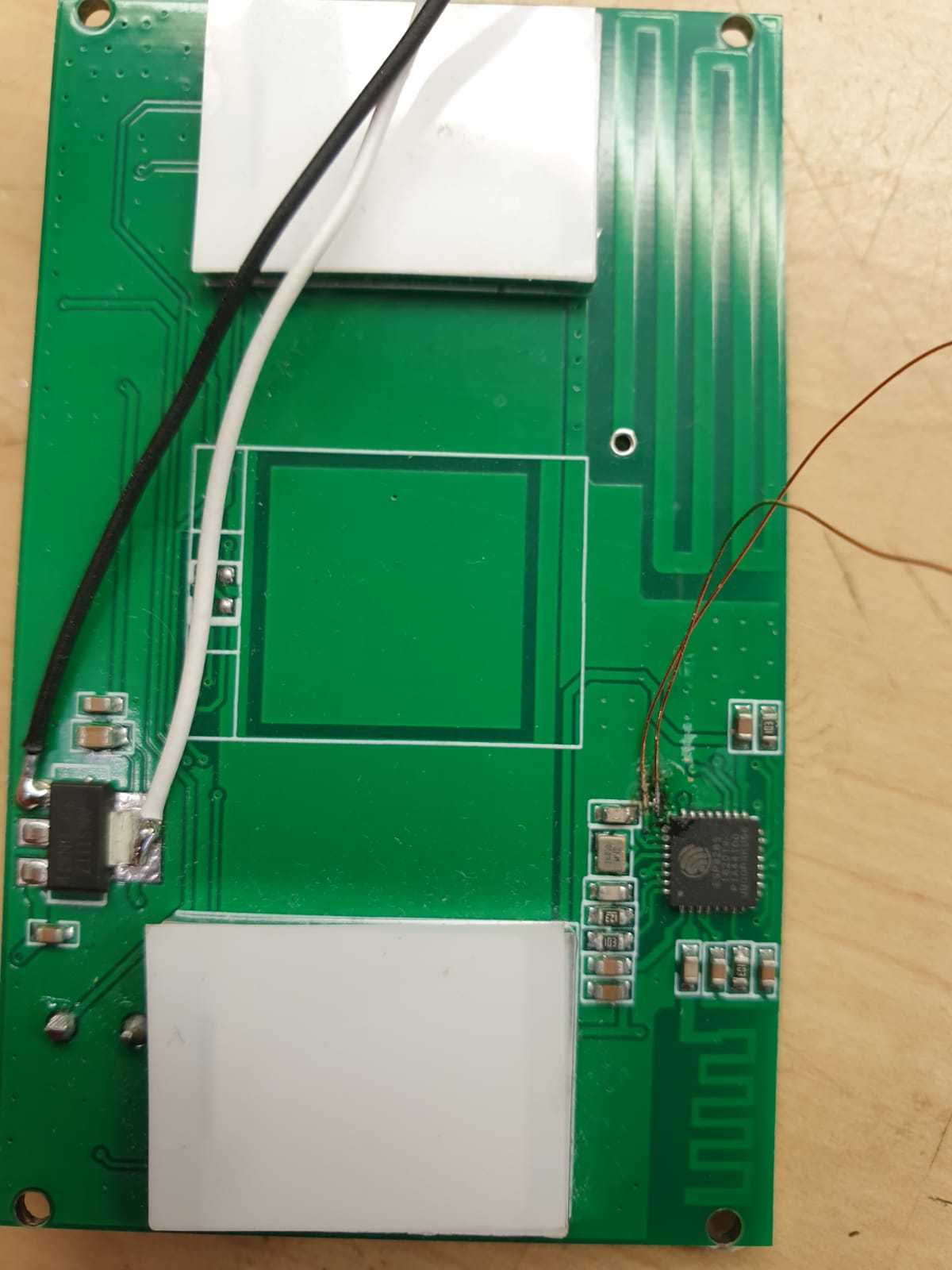
As you can see in the pic you can solder the last two wires onto these locations. The white wire is Vcc and the Black wire is Gnd.
Connecting the Usb to Serial
You are going to use jumper wires to connect the usb to serial adapter to the wires you have soldered onto the light switch.
You can connect the white and Black wires to the Vcc and Gnd of the usb to serial adapter.
NB! Make sure the USB to serial adapter is set to 3.3V
Powering Up the USB Adapter
Before you plug in the USB adapter, you going to need to short the GPIO 0 pin to gnd to get it to go into flash mode.
Take the wire you soldered onto GPIO 0 and hold it to Gnd(Black wire while you plug in the USB adapter.
Connecting Comms
Now you going to need to connect the RX and TX wires to the USB adapter.
You are going to connect the two small wires you soldered on to the USB adapter. RX of the ESP to the TX of the adapter and TX of the ESP to RX of the adapter.
Flashing the Switch
You are now going to run the Pyflasher( Flashing tool).
Once you have the flashing tool running you going to select the Bin file you downloaded and the click flash.
The flashing tool will upload the bin file and then you are done. You can then unplug and replug in the usb to serial adapter to make sure it was successful as you should have a sonoff wire access point if it was.
Remove Soldering
You can now remove the soldering on the plug and put it back together and install it.
Enjoy