Flash the Arduino Bootloader on an ATMega328
by HorizonLab in Circuits > Arduino
5110 Views, 1 Favorites, 0 Comments
Flash the Arduino Bootloader on an ATMega328

This tutorial allows us to load the Bootloader in case the ATmega, present on a board of our creation, is virgin; as for example in the case in which you want to realize the Drivemall.
Shopping List
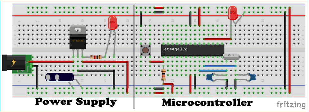
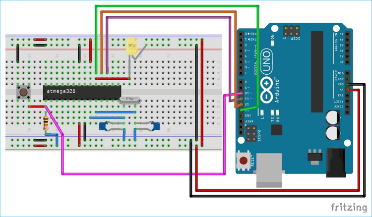
- To load the bootloader:
- Arduino (to be used as a programmer)
- ATMega328p (micro target on which to write the Arduino bootloader)
- 16MHz quartz crystal
- 2x 22pF ceramic capacitors
- 1x 10Kohm resistor
- 1x button
- 1x Breadboard Various cables
** Optional to power the new arduino **
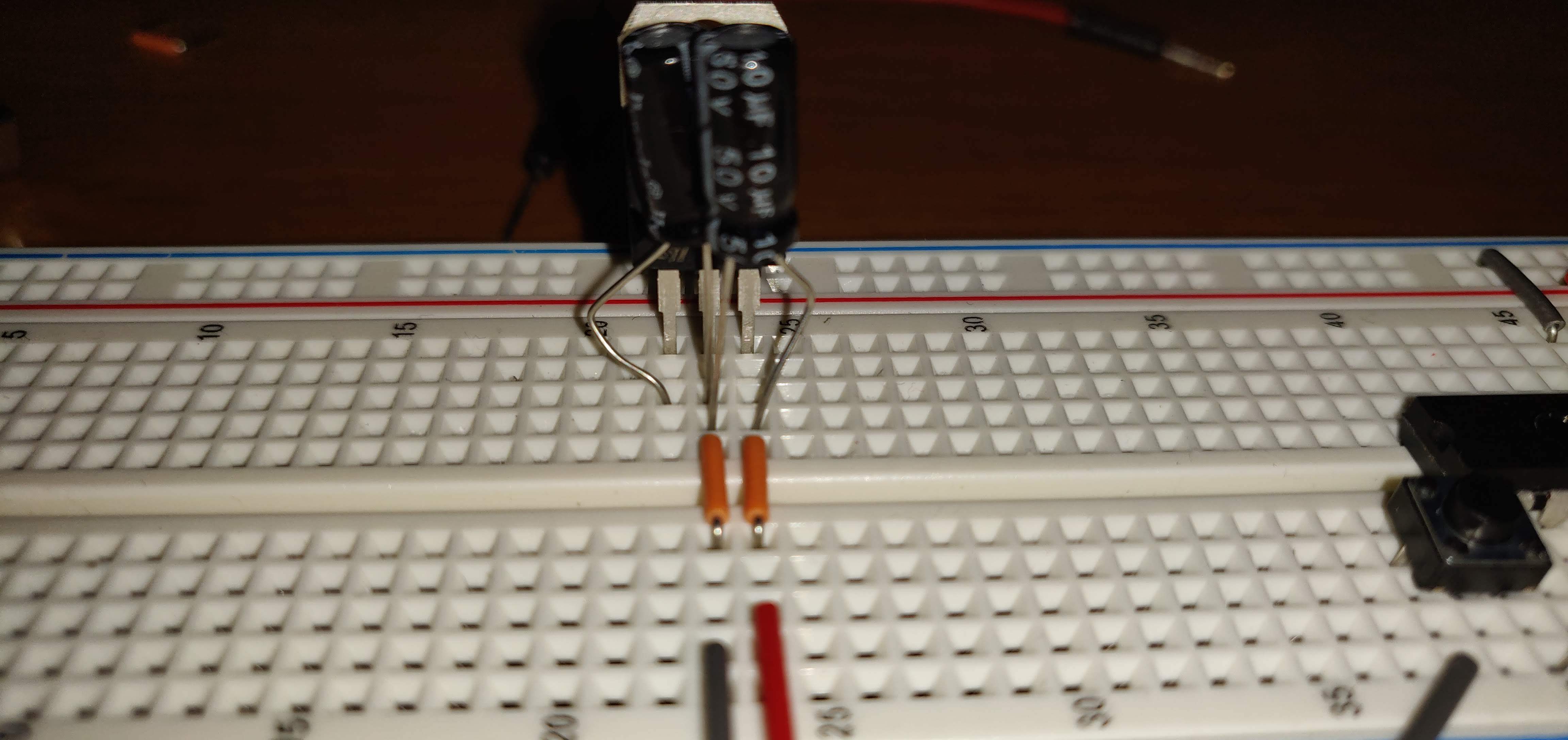
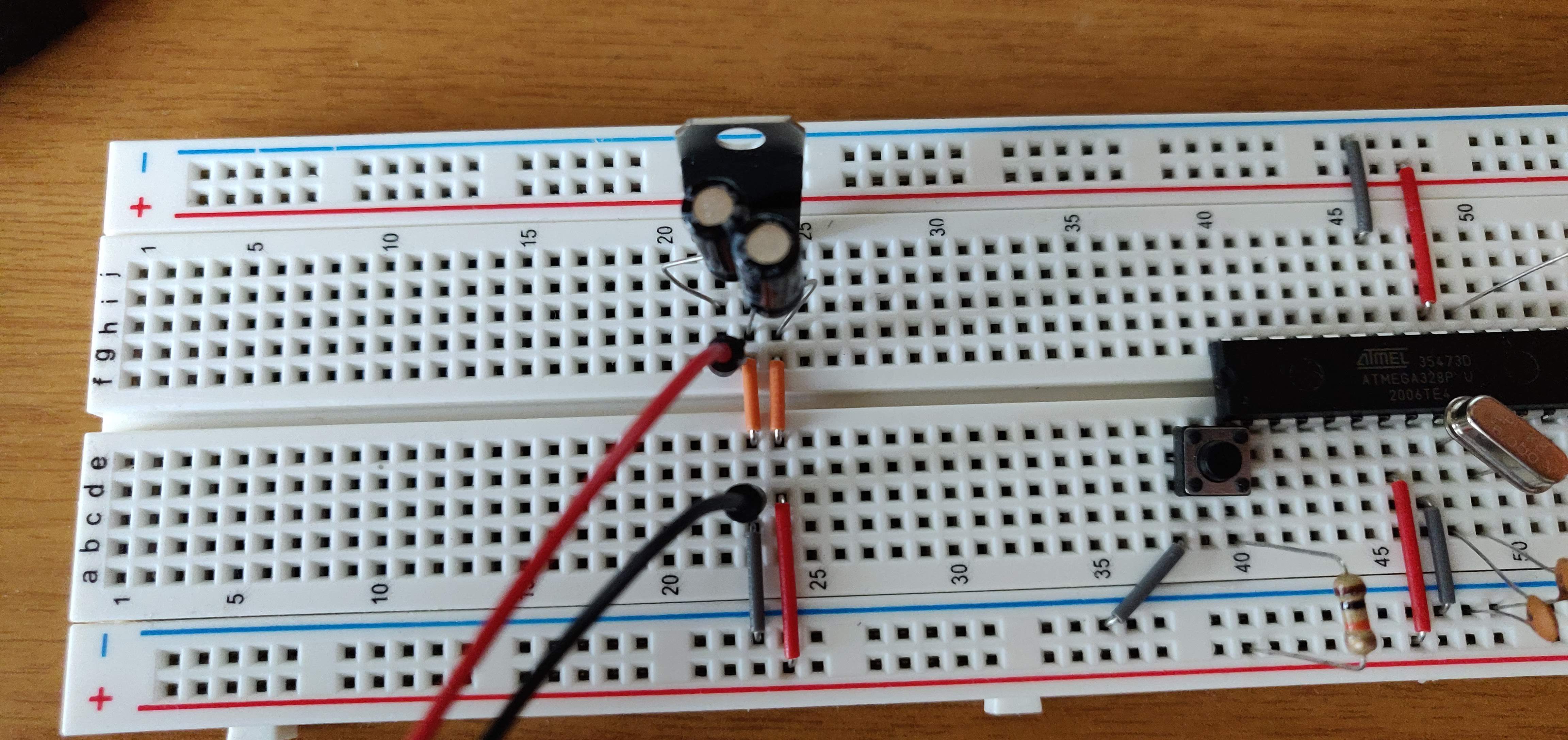
- 2x 100uF electrolytic capacitors
- 1x linear regulator LM7805
- To upload sketches
- Arduino UNO (without ATMega) or alternatively a USB serial converter (FTDI module) The arduino on breadboard
Upload Bootloader on the ATMega328
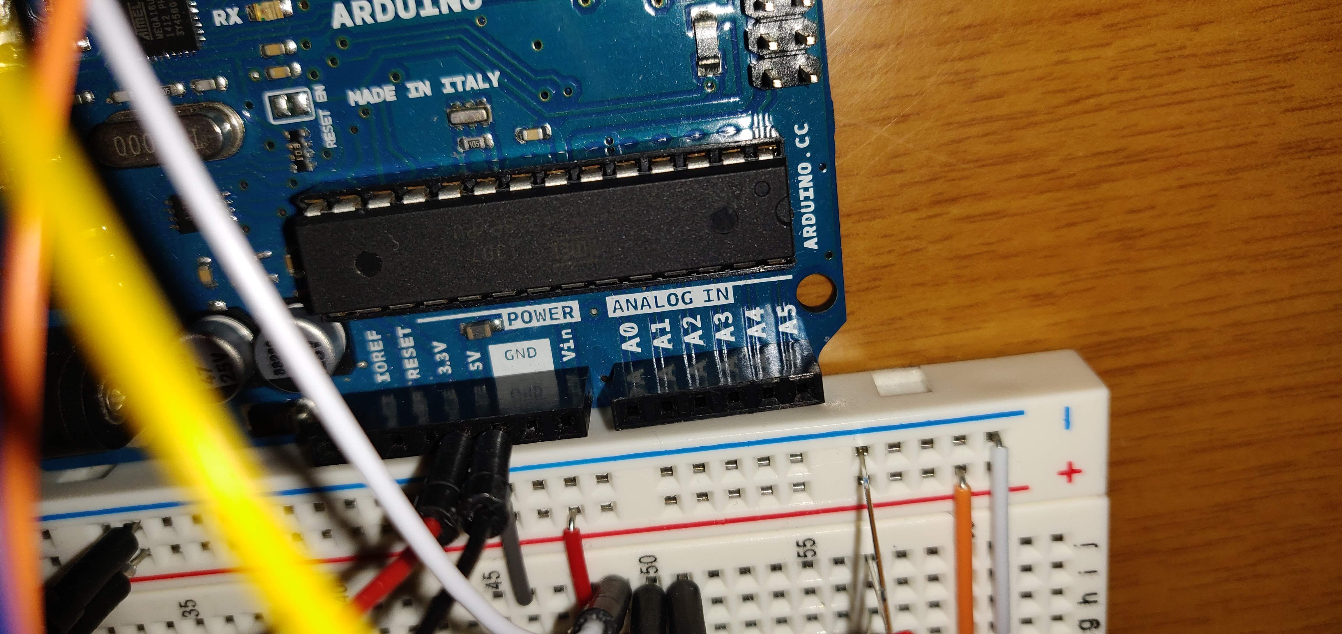
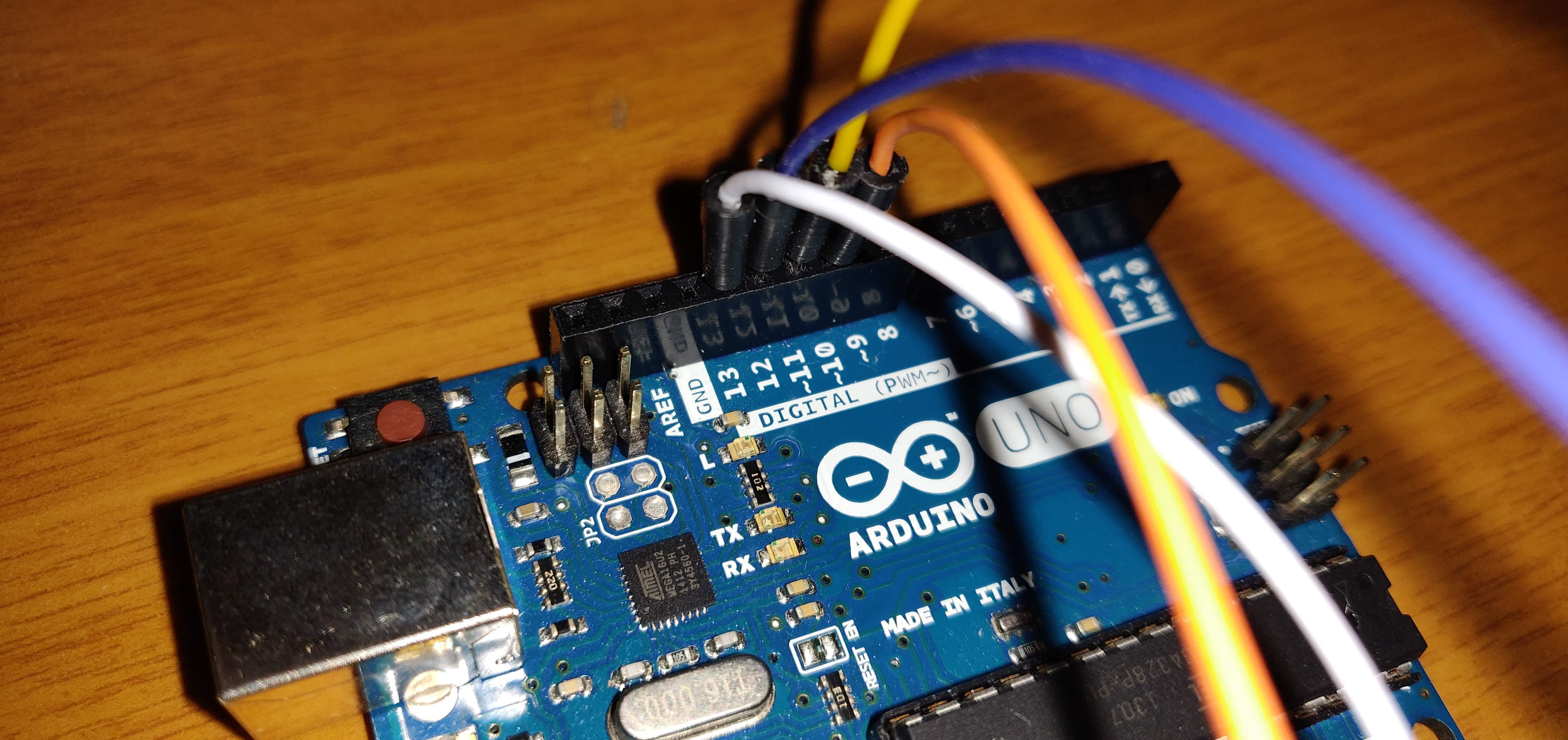
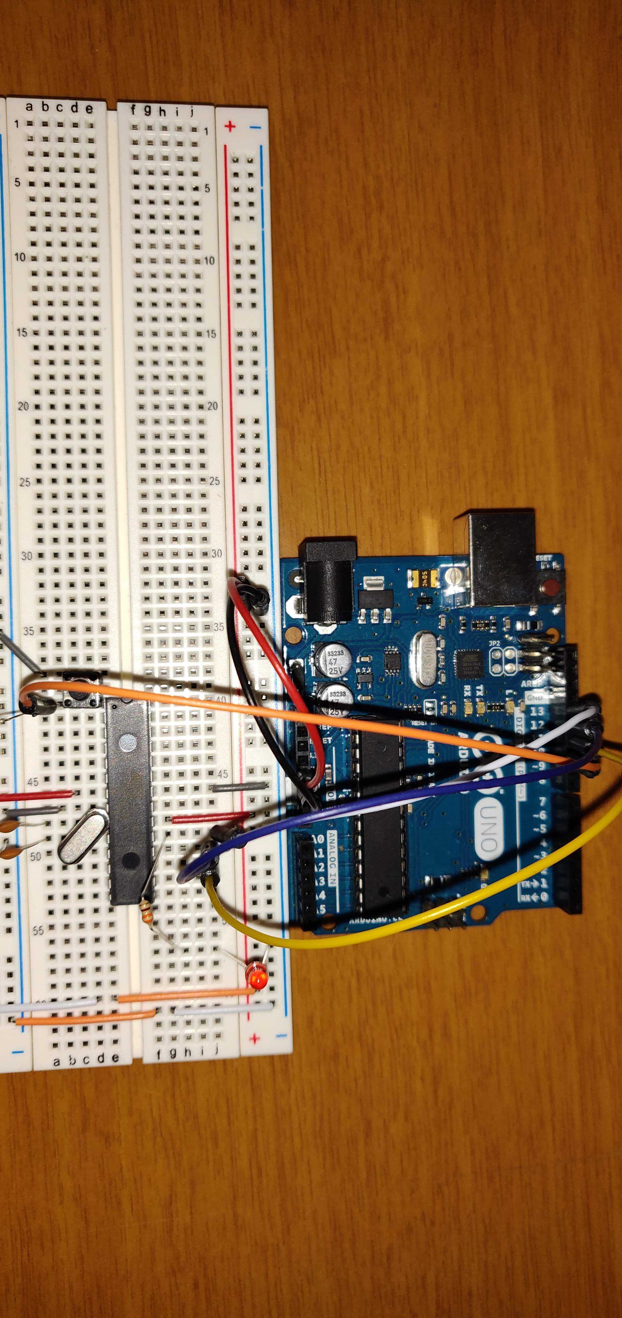
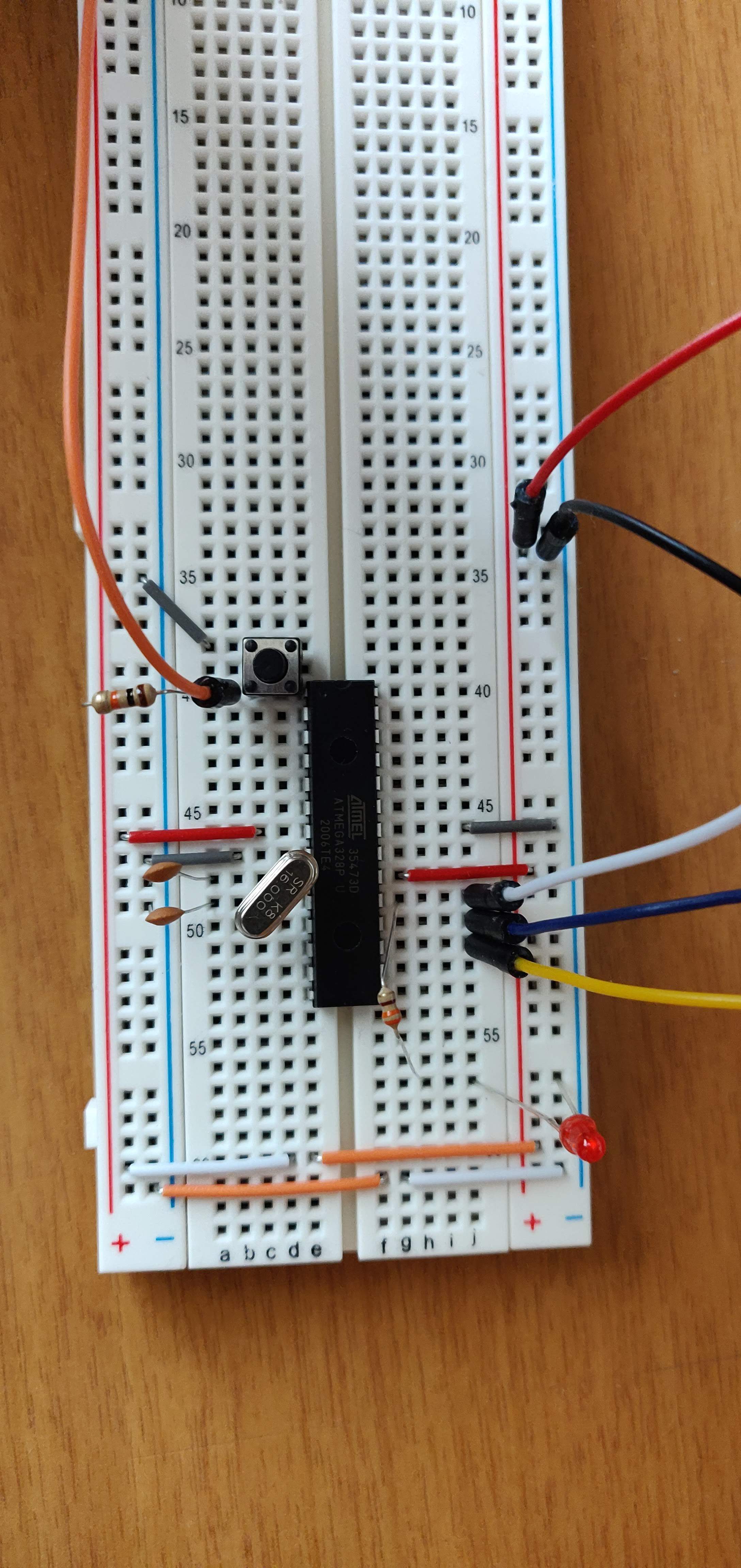
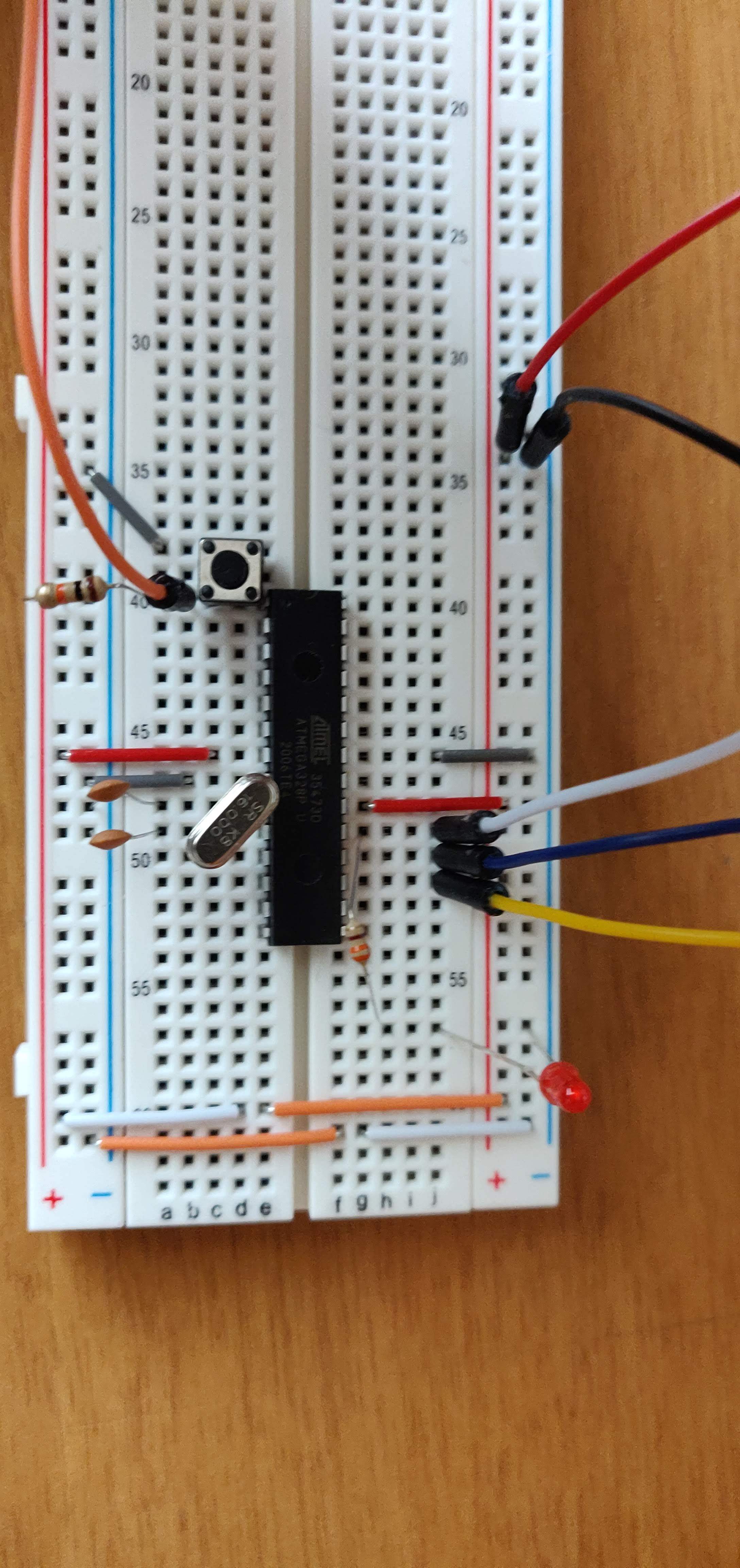
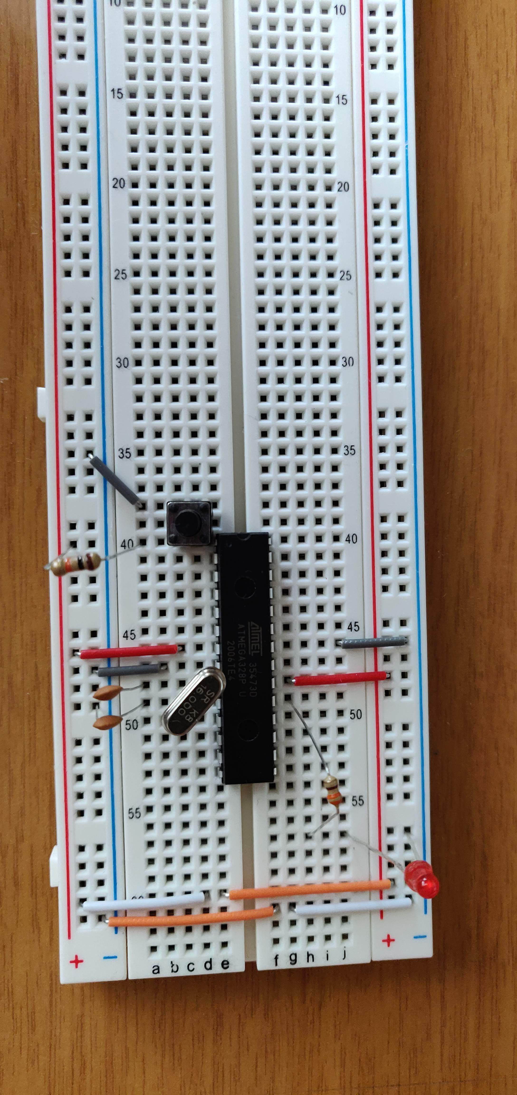

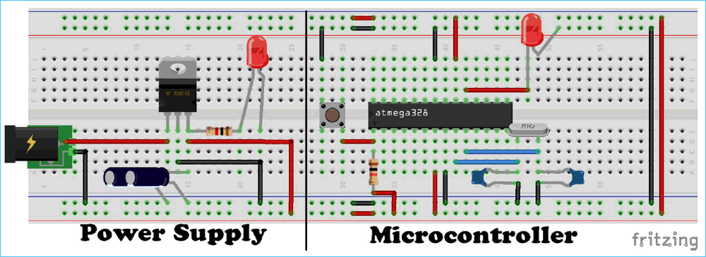
1) Build the new Arduino circuit following the schematic.
2) (Optional) Build the power supply circuit.
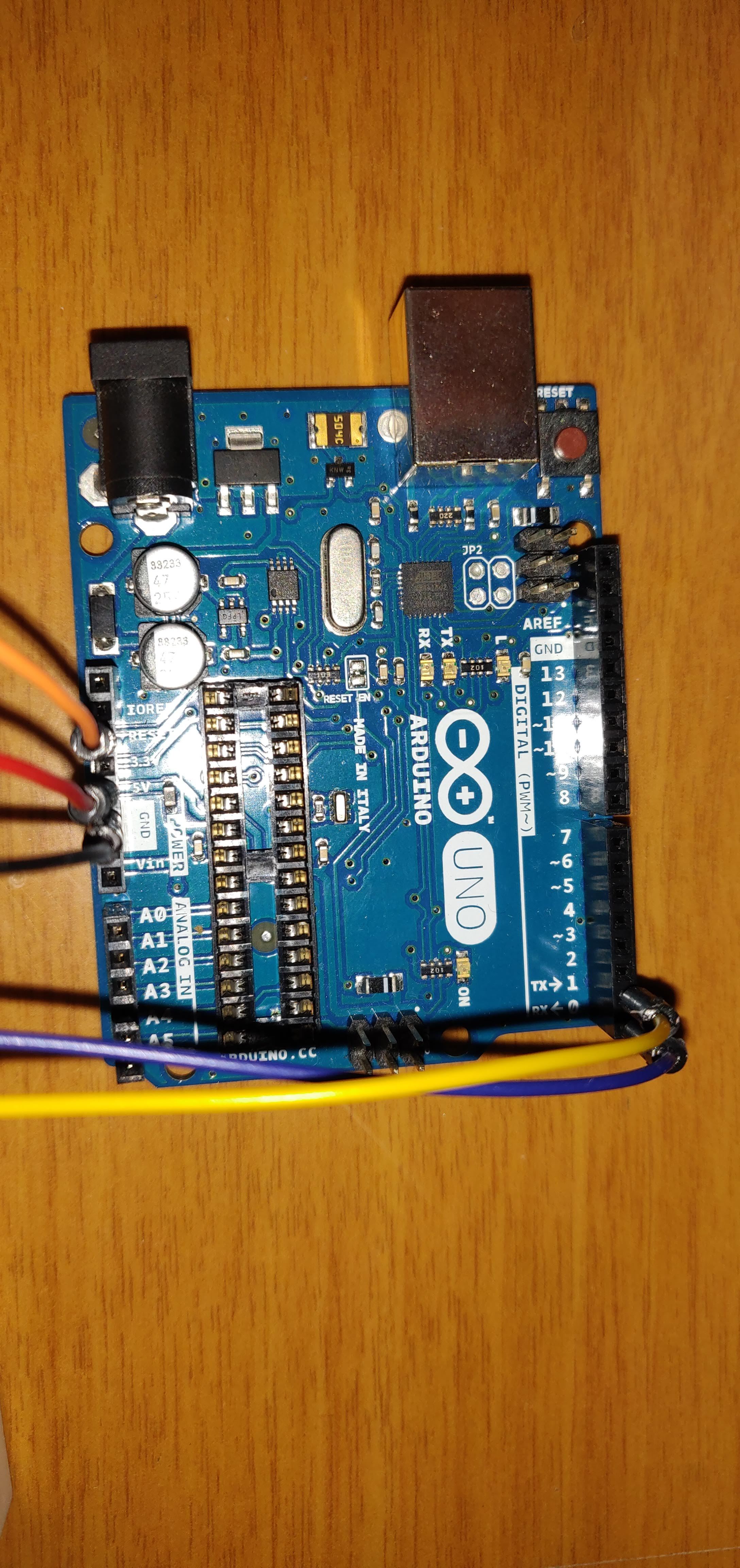
3) Prepare the Arduino so that you can load the bootloader on the ATMega328.
- Connect the Arduino to the PC
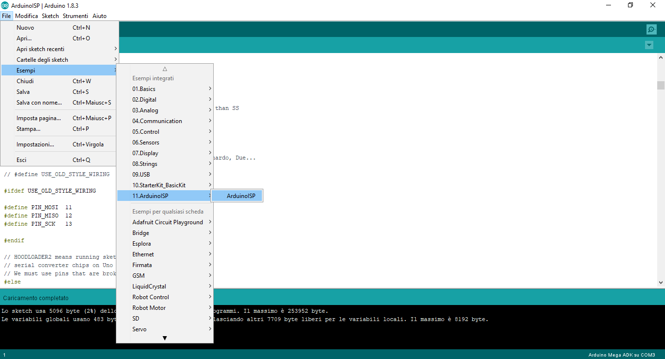
- Open the Arduino IDE and load the ArduinoISP example by clicking on File -> Examples -> ArduinoISP or alternatively using the attached fw.
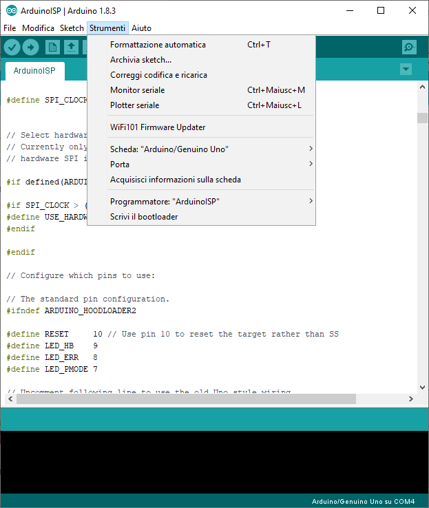
- Select the Arduino board in use in the Tools -> Boards menu.
- Make sure that the port in use (Tools -> Port) corresponds to that of the Arduino connected to the PC.
- Load the skecth by clicking on the "Load" button
4) Connect the Arduino board to the custom circuit following the diagram (To avoid problems, disconnect the Arduino from the PC before connecting it to the custom circuit).
5) Connect the Arduino to the PC and start the Arduino IDE.
- Then select "Arduino / Genuino Uno" as board by clicking on "Tools -> Boards -> Arduino / Genuino Uno".
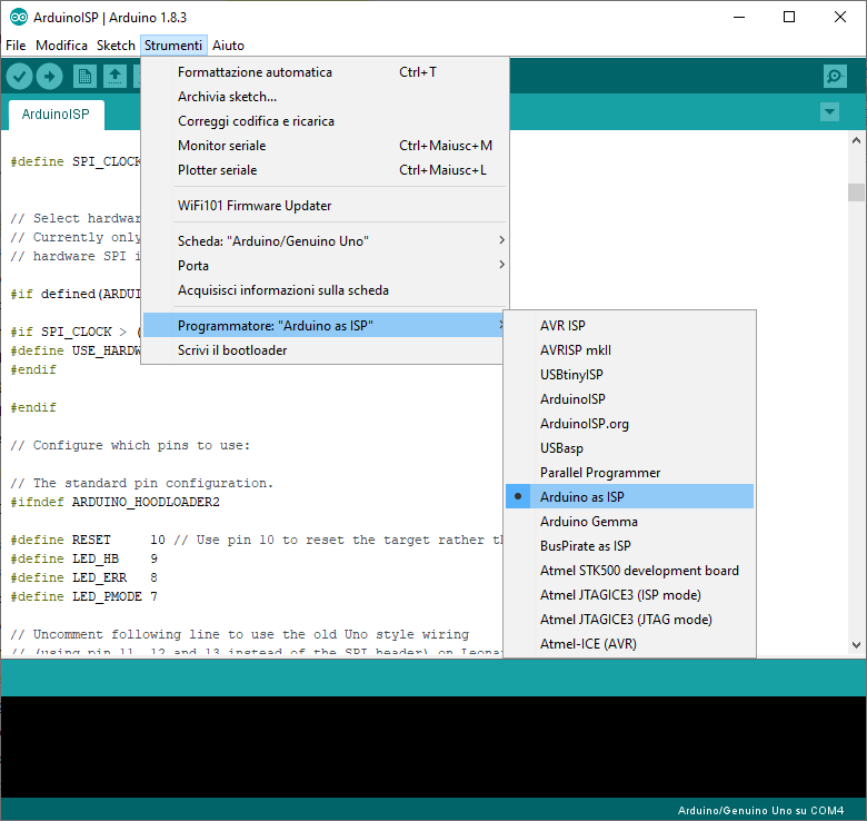
- Select "Arduino as ISP" by clicking on "Tools -> Programmer -> Arduino as ISP".
- Make sure that the port corresponds to the Arduino board connected to the PC, by selecting the appropriate item in "Tools -> Port".
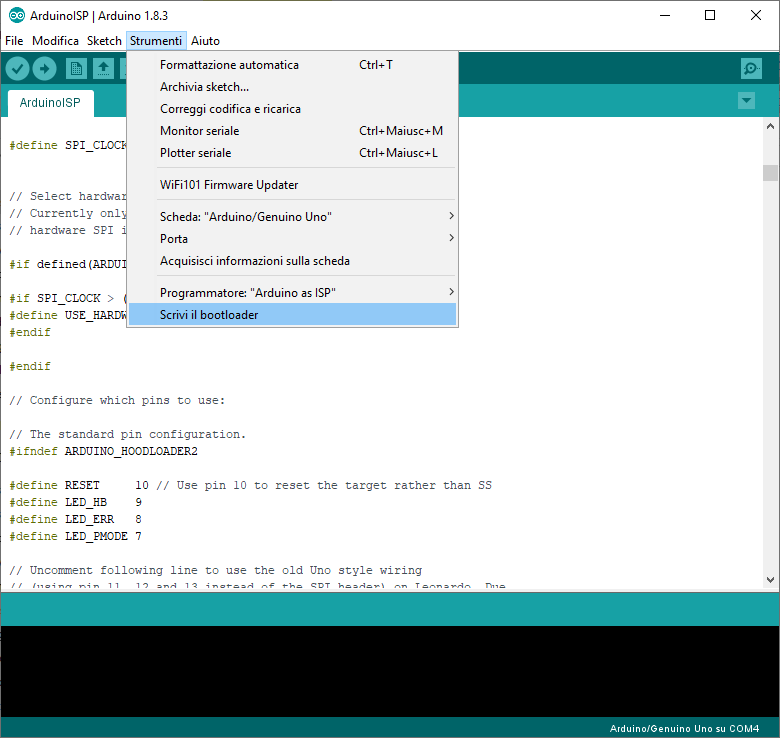
- Load the bootloader by clicking on "Tools -> Burn Bootloader".
Upload a Sketch With Another Board Arduino Uno
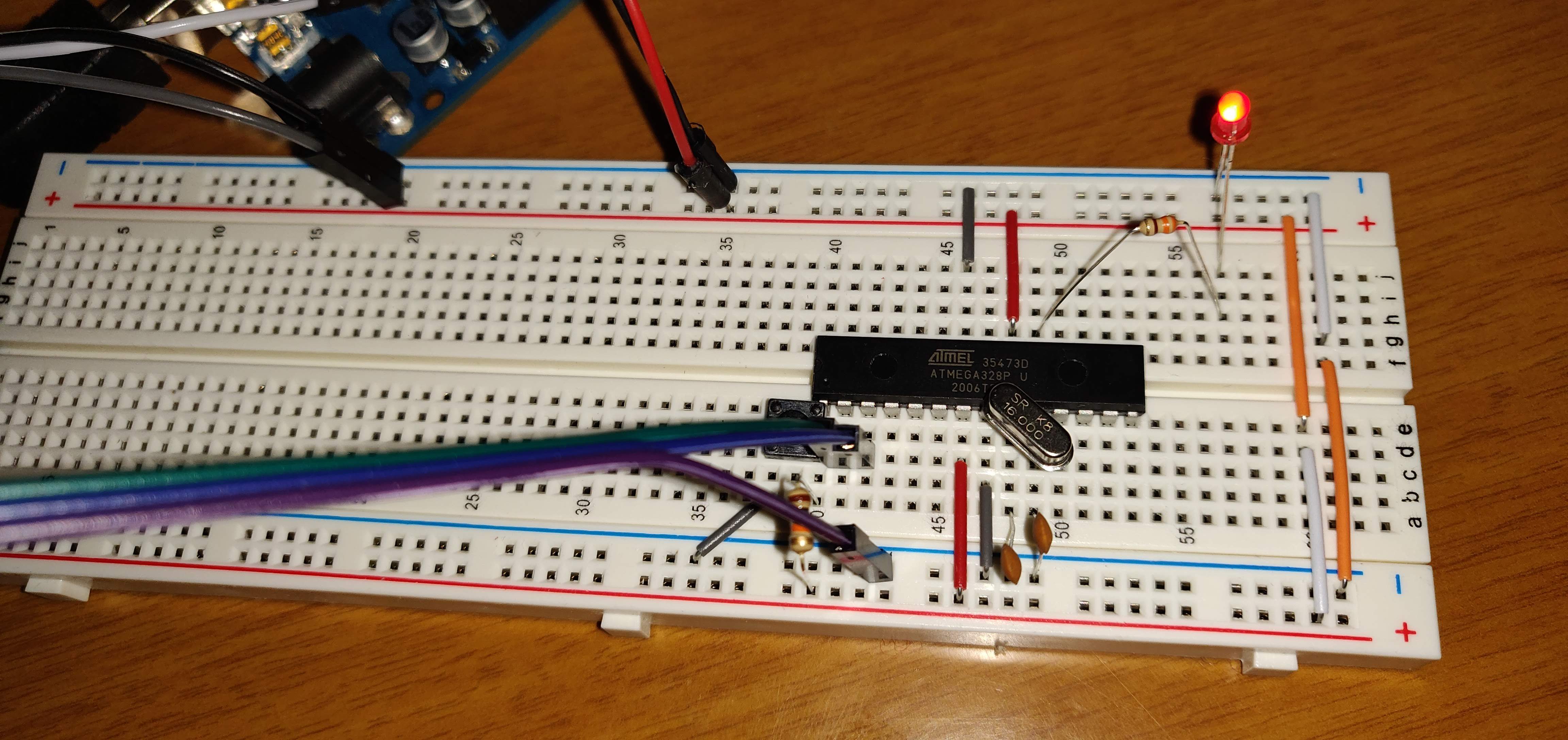
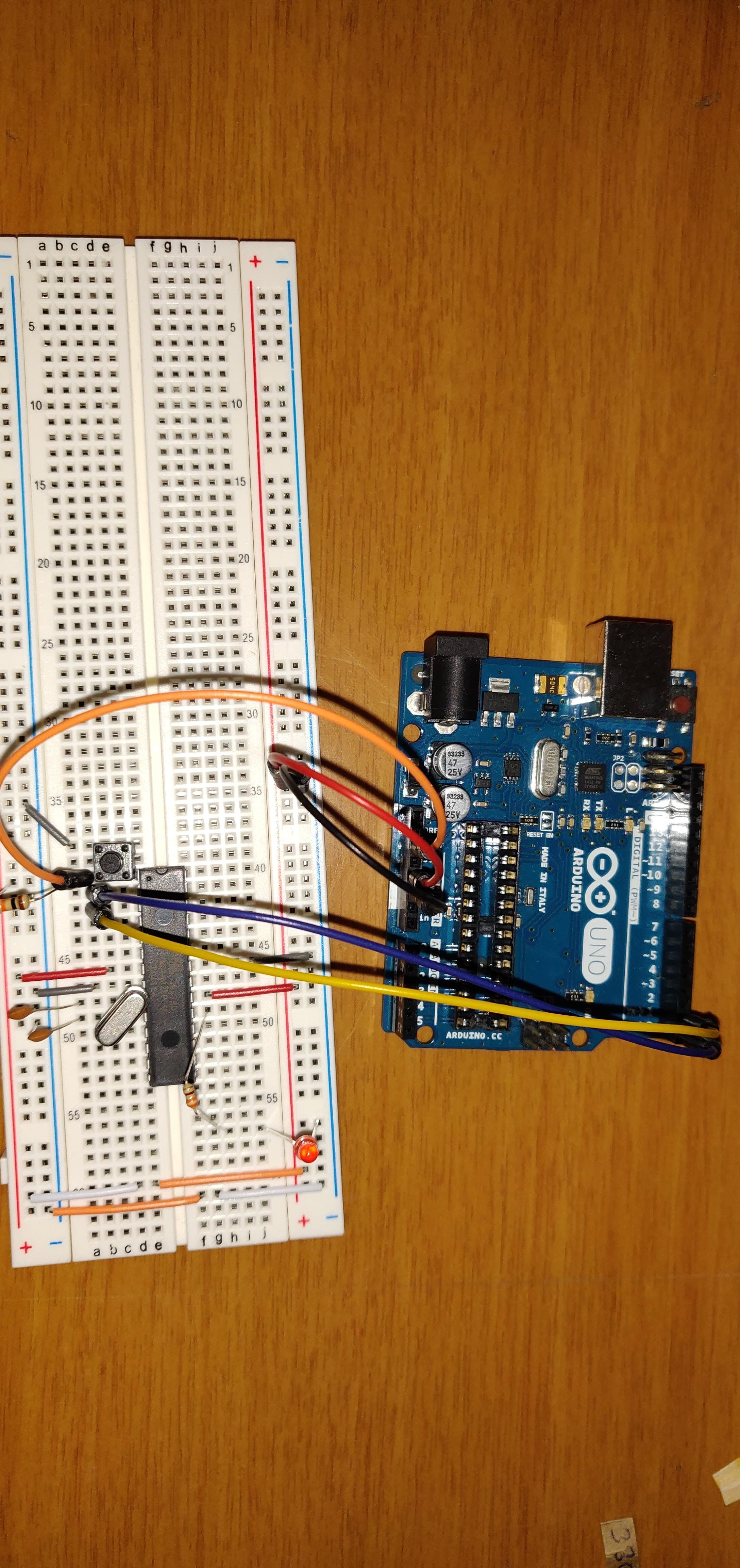
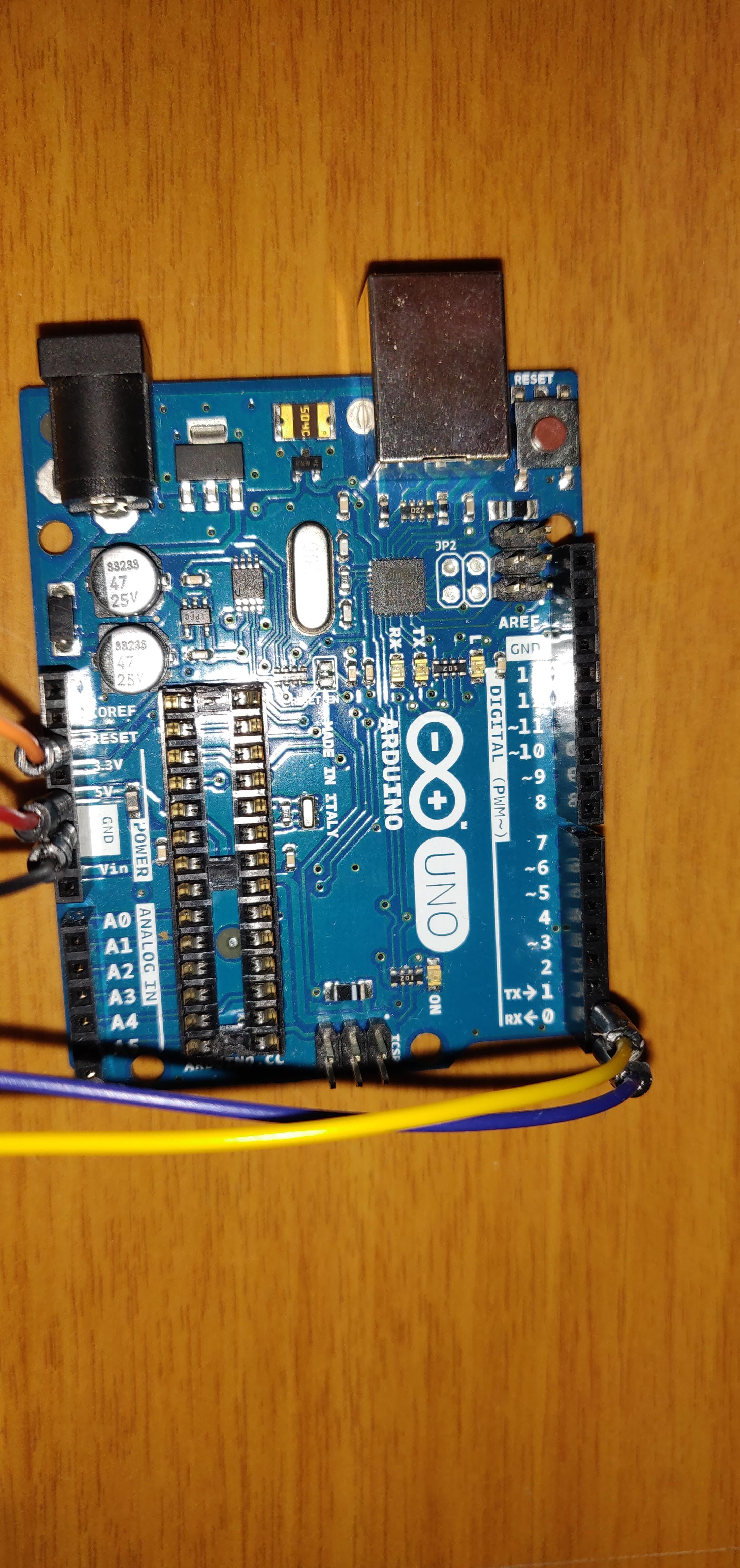
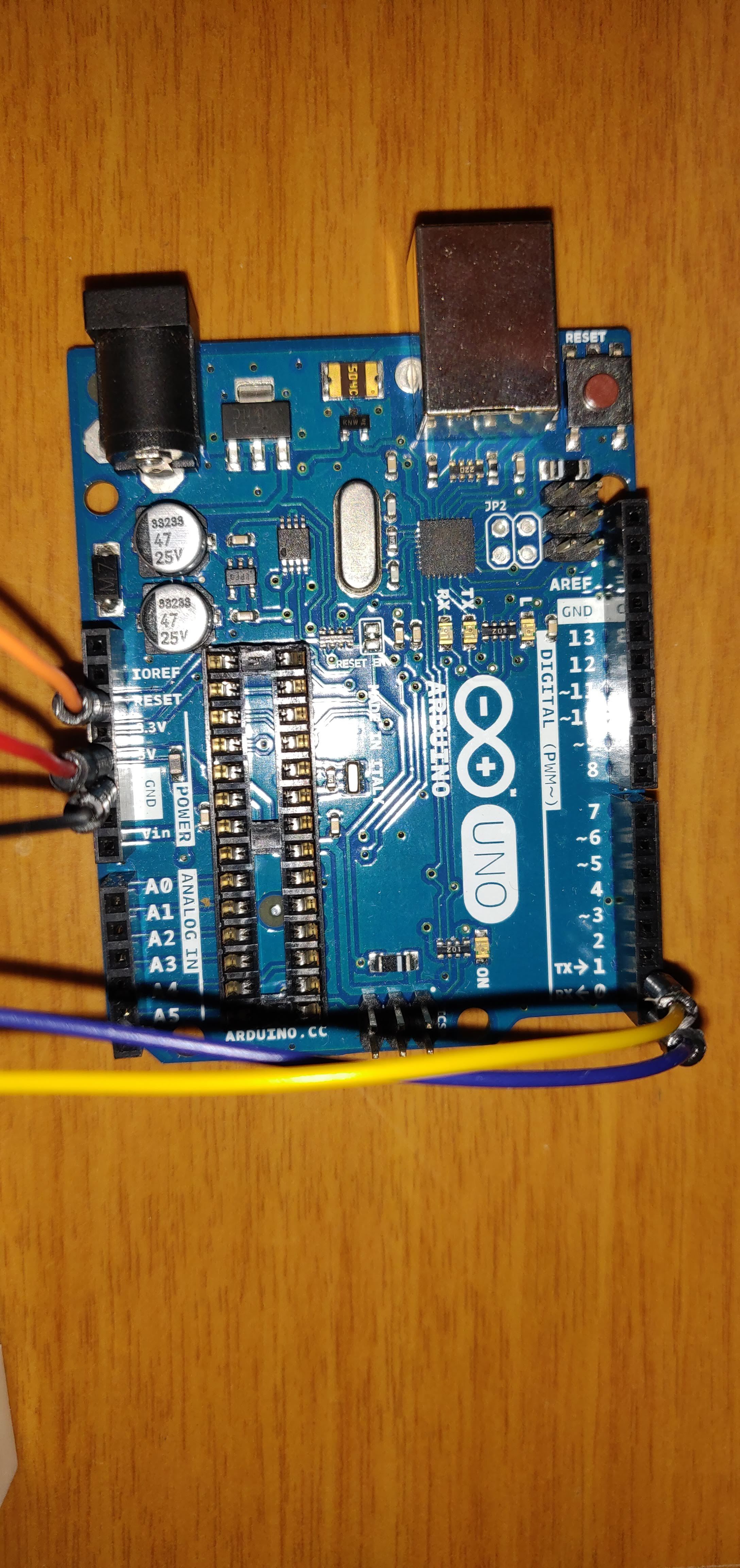
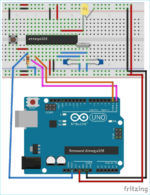
In order to load a sketch on the Arduino breadboard, you need to use either another Arduino UNO board or a USB serial converter such as the FTDI module.
- Arduino UNO as a programmer
If you want to use another Arduino UNO to program the Arduino breadboard, you need to:
- 1) Remove the microcontroller from the board.
- 2) Connect the board to the arduino bradboard as indicated in the schematic.
- 3) Connect the Arduino to the PC.
- 4) Choose or Create an Arduino sketch.
- 5) Select "Arduino / Genuino Uno" as board by clicking on "Tools -> Boards -> Arduino / Genuino Uno".
- 6) Select "USBasp" by clicking on "Tools -> Programmer -> USBasp".
- 7) Make sure that the port in use (Tools -> Port) corresponds to that of the Arduino connected to the PC.
- 8) Click on the "Load" button.
USB Serial Converter
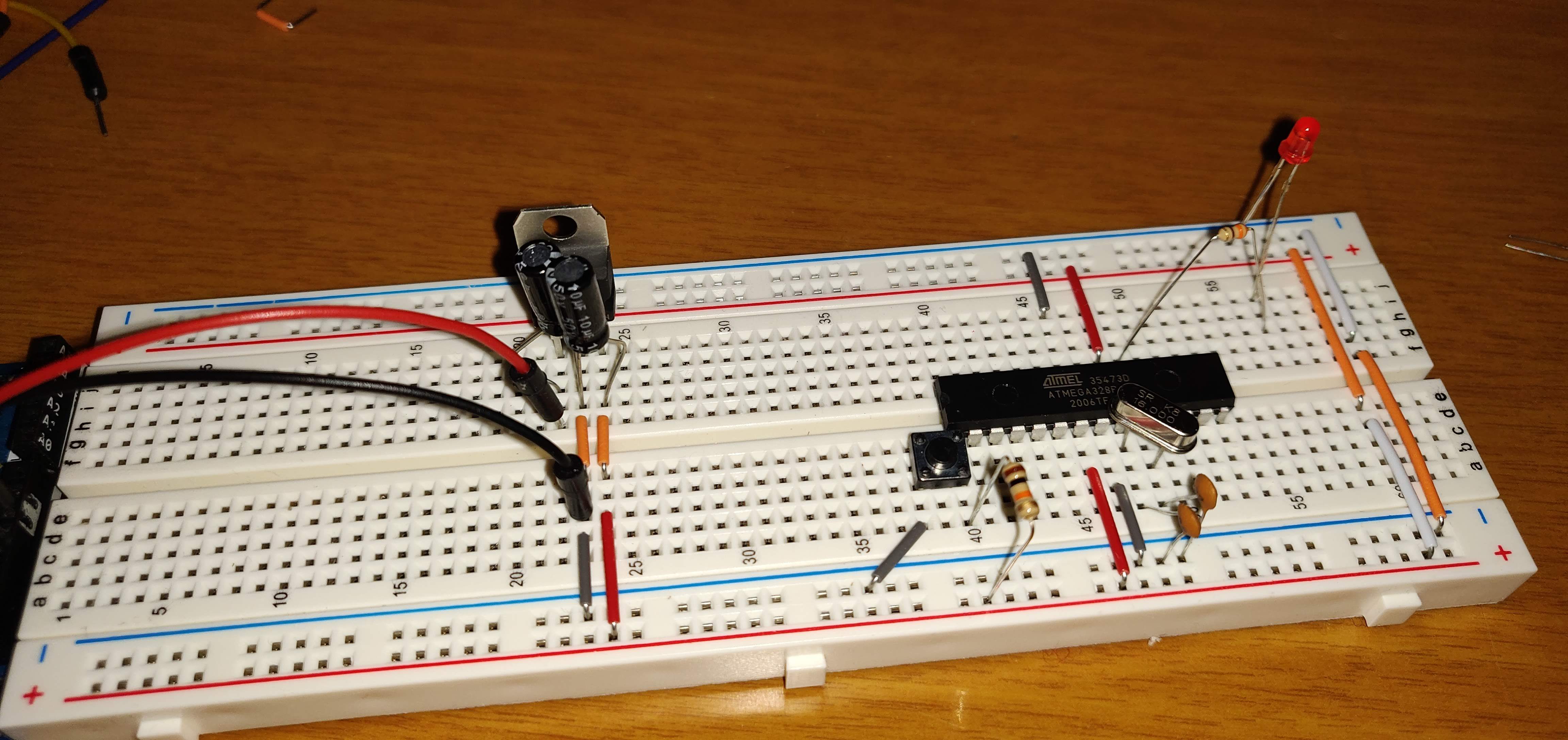
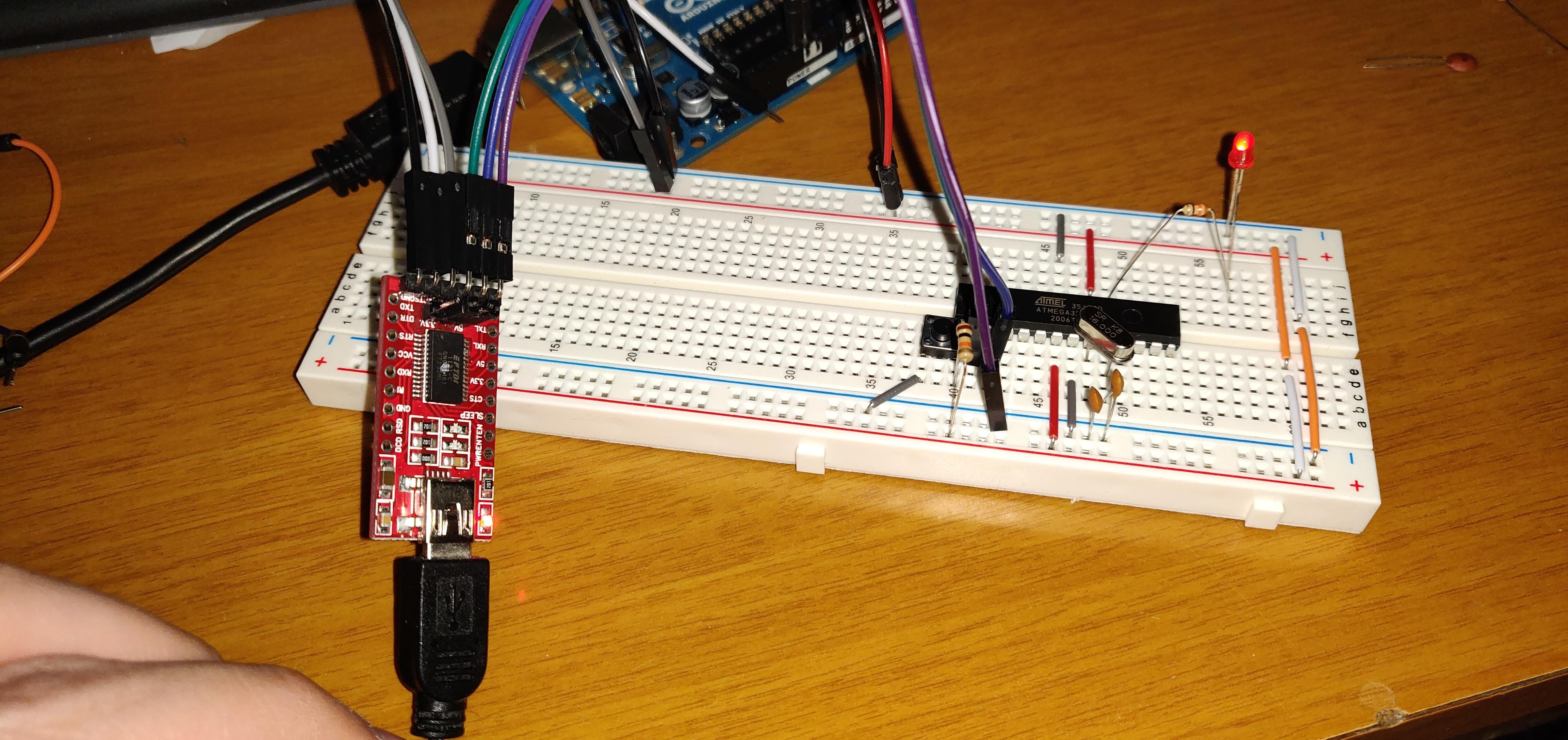
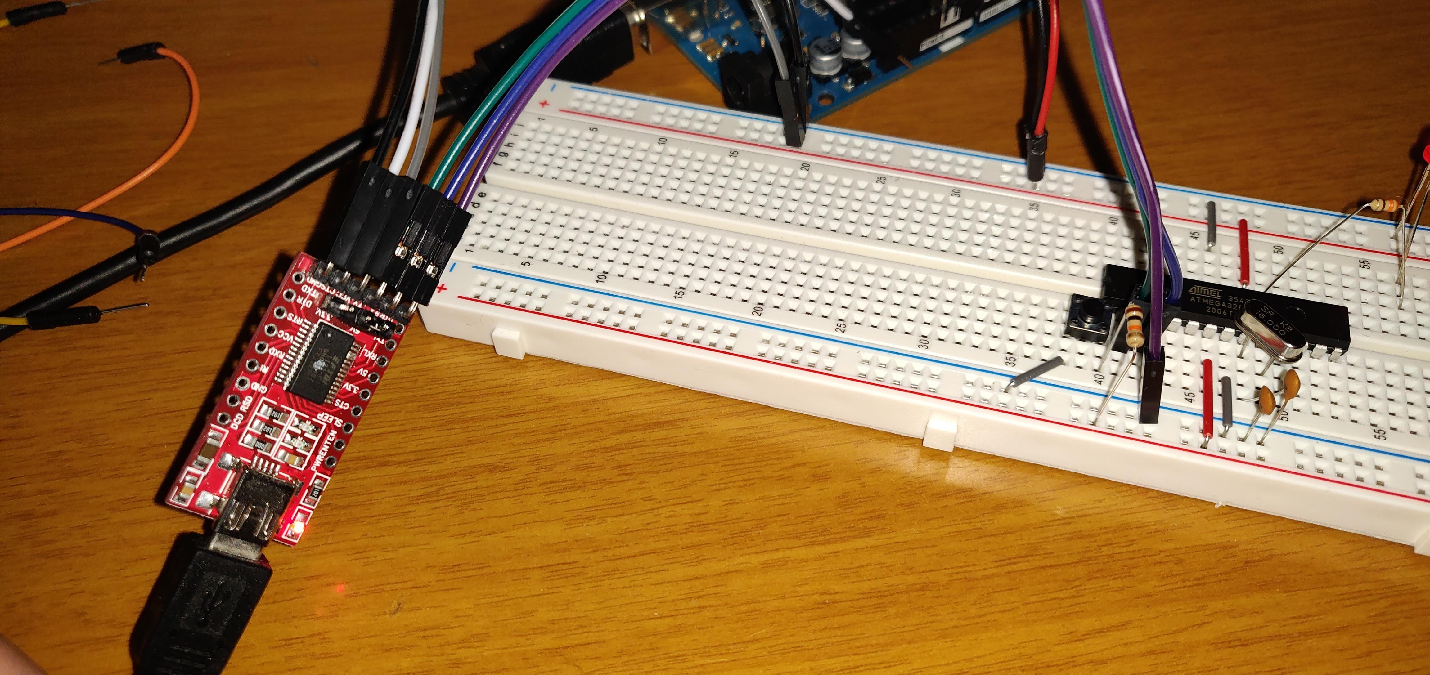

If you don't have an Arduino UNO to use as a programmer, you can use a USB serial converter.
In this case you need to:
- 1) Connect the converter to the Arduino breadboard as follows: pin RXD -> pin Tx ATMega328 (pin 3) pin TXD -> pin Rx ATMega328 (pin 2) GND -> GND (pin 8) 5v -> Vcc (pin 7) pin DTR -> pin RESET ATMega328 (pin 1) If the module does not have the DTR pin, it is still possible to load by performing a manual reset.
- 2) Connect the FTDI module to the PC.
- 3) Choose or Create an Arduino sketch.
- 4) Select "Arduino / Genuino Uno" as board by clicking on "Tools -> Boards -> Arduino / Genuino Uno".
- 5) Select "USBasp" by clicking on "Tools -> Programmer -> USBasp".
- 6) Make sure that the port in use (Tools -> Port) corresponds to that of the Arduino connected to the PC.
- 7) Click on the "Load" button.
ATTENTION:
- If the FTDI module does not have the DTR pin, hold down the RESET button on the breadboard and then click on the "Load" button. Press and hold until the IDE displays the "Uploading…" message. As soon as this message is shown, release the button. At this point the upload should proceed without problems.