FirstContact: an Automatic Contact Lens Applicator
by lance lee in Workshop > 3D Printing
223 Views, 1 Favorites, 0 Comments
FirstContact: an Automatic Contact Lens Applicator
Ever get bothered that when you put on contact lenses, you mess it up too many times and you just wish there was a better way? Here you go!
Supplies
You will need:
- A 3D printer
- Ultimaker downloaded to your computer
- PLA filament (for the main chassis)
- ABS filament (for the connecting rods and the eyelid receptacles)
- A laser cutter
- Laser cutting software such as LightBurn (you can also use Inkscape to alter the joints if need be)
- Acrylic paneling (for the joints) (note: thickness doesn't matter too much, but 2mm thick acrylic is preferable)
- Rubber bands
- Scissors
Optional:
- Masking tape
- Tweezers
Prep
Download the files provided below.
I suggest having replacement nozzles when 3D printing.
Exporting the stl files will depend on what 3D printer you use and what filament, however to replicate this you will need PLA and ABS.
I also suggest
Main Chassis
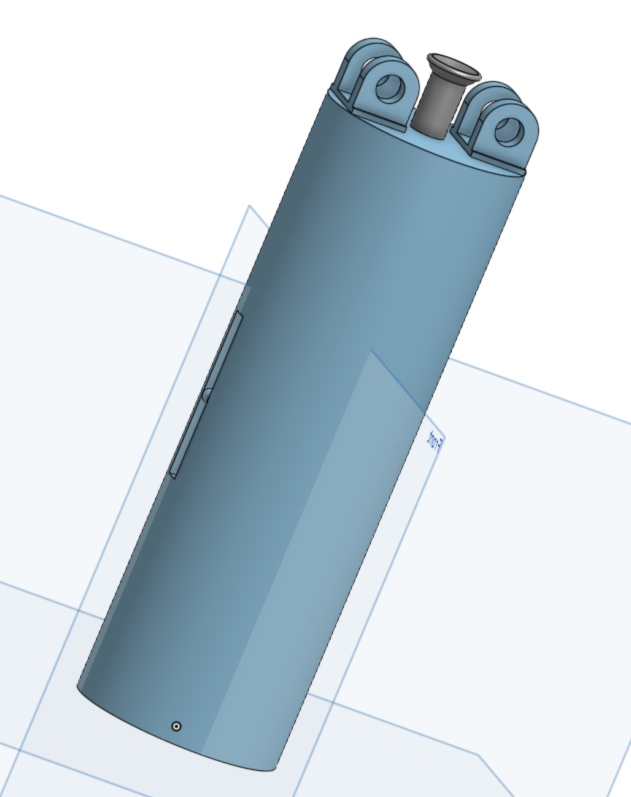
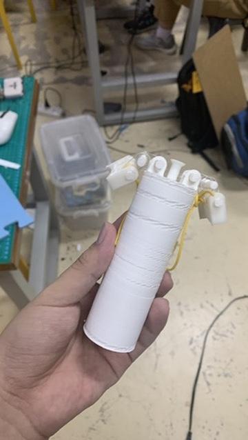
First, print the body provided in final applicator body.stl using PLA filament. I suggest using 0.8 mm nozzles to make the process faster, although I would not recommend speeding up the print through the nozzle speed at it may come out with defects like what you can see here.
Note: Earlier revisions of this design featured a much larger body than the final product. I would recommend using the larger body, however personally I didn't find the smaller body any less convenient.
Downloads
Joints
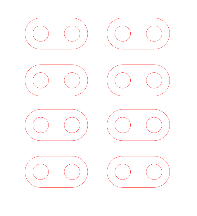
Using a laser cutter, cut out the figures provided in joints.pdf. This allows the receptacles to articulate well with the main chassis and the connecting rods.
Note: I suggest if you're printing the larger one, to make sure to print extra joints and connecting rods. Two sets should be enough for the larger set-up, however.
Connecting Rods
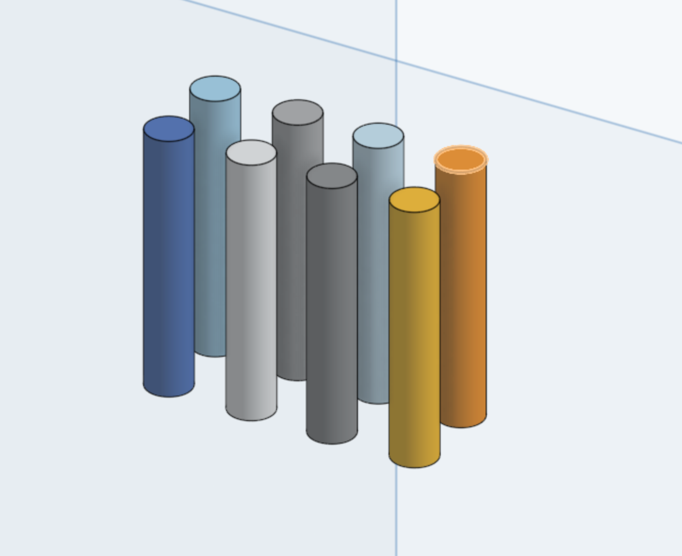
Print the file provided in conrods.stl using ABS plastic. Only 6 of these are required, however I included 8 in case an extra is needed. Optionally, you may want (read: need) to wrap these in one or two layers of tape when assembling the full object. The rods are loose otherwise. I suggest using a 0.4 mm nozzle for these, as the finer level of detail with a 0.4mm nozzle helps with the connecting rods' rigidity.
Eyelid Receptacles
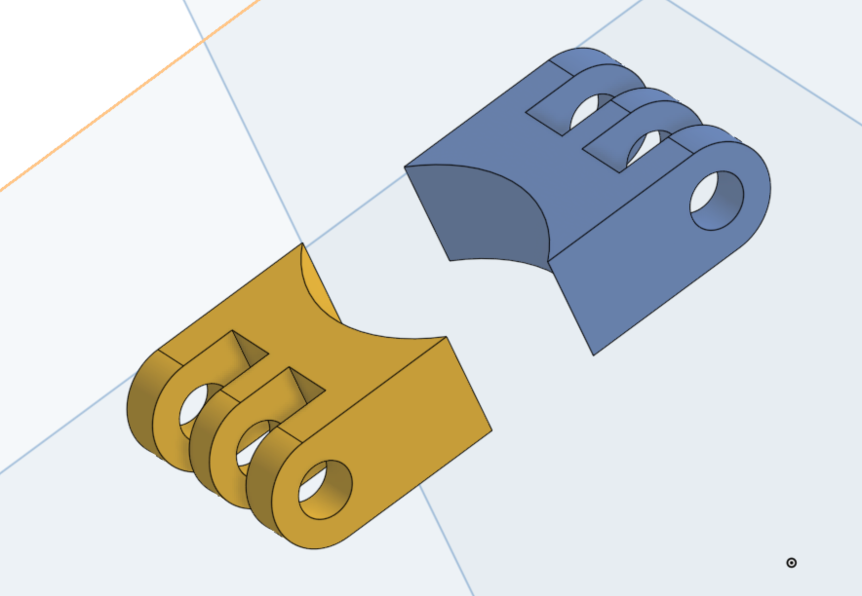
Print the receptacles found in, well, receptacles.stl. if I were to change a part of this final assembly, I would have made the curved bits way thinner than they currently are while keeping the joints the same.
Assembly, Part 1
If everything has been printed, now is the time to assemble the final object.
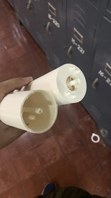
Cut the rubber bands so they become long strands. Thread one end of a rubber band through the holes in the main chassis such that when you finish, they wrap around the pole in the middle of the hole. You can use tweezers to make the threading process much easier. Then, tie off the rubber band and cut any excesses off if you need or want to.
Now, take the other end of the rubber band and thread it through the middle hole of the receptacle. You should have one end loose and one end tied to the main chassis. Pull at the loose end so that when you put the receptacle in the approximate location, the rubber band should be extended. If not, pull it further until you reach the desired tension. Then, tie the rubber band off at the receptacle end, and cut accordingly. I suggest making it quite a lot tenser than I have it in my images, as the rubber band being too loose could make the eyelid receptacles not open us properly.
Repeat this process with the other rubber band.
You should be left with the acrylic joints, connecting rods, and the eyelid receptacles joined to the main body with rubber bands, with one on each side.
Assembly, Part 2
Now, insert two of the acrylic joints between the corresponding holes on one side of the chassis such that the joints are right next to each other. Wrap a connecting rod with one to two layers of masking tape, and then insert it into the joints. Take two more acrylic joints and add them in between the joints, and add another connecting rod. Finally, wrap another connecting rod in masking tape, same procedure as the first time, and place one joint per slot within the receptacle, before inserting the connecting rod.
Repeat this process for the other side.
Note: If you're printing the larger model provided, I suggest repeating the joint-to-joint steps one or twice, adding masking tape to the connecting rods as necessary to make sure the rods don't fall out during use.
Usage
To use the device, place a contact lens on the inverted dome. Then, close the receptacles together. Close your eyes. Put the receptacles up to your eyelids. Release them when they're secure on your face. Then, push in until you can feel the contact lens on your eye. I highly recommend dousing the contact lens with the prescribed lubricant of your choice before application.
Conclusion
You did it!