First-Arduino-Project

My initial idea was to create a mask with a visor that could open at the press of a button, accompanied by a light turning on when the visor was raised. I aimed to blend functionality with aesthetics, envisioning a piece that was both practical and visually appealing. However, as I worked on the project, I decided to tweak my concept slightly.
Instead of a wearable mask, I crafted a box-like structure that retains the same mechanical features. While not wearable, it still opens the visor with a button press and activates a light when the visor lifts.
I found the idea of creating not just a functional item but also a decoration for my room intriguing. This project became an opportunity to explore both my creativity and technical skills
Supplies


Tools:
- Soldering iron
- Solder
- Cable cutter
- Cable stripper (optional)
- Screwdriver
Other:
- Wooden plank
- Screws
- The second image shows a corner support used to connect two components. While this is one way to achieve the connection, it's not the only method. There are other components available that can accomplish the same goal.
I initially cut the right pieces from the wooden plank on a laser cut machine. It doesn't have to be cut by a laser cut machine so any other way is also possible
Create the Design


Before anything else, I started by creating a sketch design to ensure I knew where to place everything, such as the button. This gave me a clear picture of how my design would look. As a result, I had a better understanding of what I needed and was able to keep the design realistic and feasible.
Make the Circuit Design

After creating the sketch design, I knew what kind of mechanism I wanted for my project. I envisioned a mechanism where you press a button, and the visor goes up, activating the LED light. When the visor goes down again, the LED light turns off. To achieve this, I first created the circuit design on Tinkercad. This helped me understand how the mechanism works.
Test 1


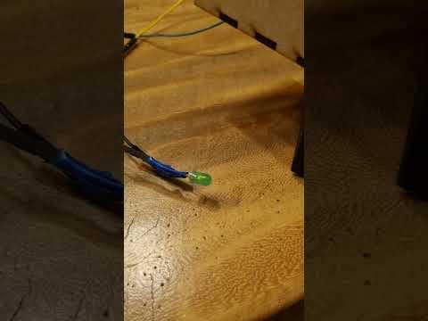
After designing the circuit on Tinkercad, my next step was to create a proof of concept to check if it would actually work. I used the same materials that I planned to use for the final product, but without the final design elements, to test if everything functioned correctly.
Laser Cut
.png)
After successfully testing the proof of concept, I proceeded to create the design using wooden planks. I used laser cutting to ensure precise dimensions and shapes for the design. Additionally, I incorporated holes in strategic locations for efficient cable management
Building the Design Part 1: Case


I began assembling the design to get a quick preview of where I would place the Arduino and breadboard. Despite having a sketch of the design, I wanted to confirm the placement to ensure everything fit perfectly.
Building the Design Part 2: Solder


Once I determined the placement for everything, including cables, I proceeded with soldering the cables onto the breadboard, LED light, and button. I positioned the Arduino and breadboard in their designated spots and began organizing the cables for efficient management.
Input configuration for the Arduino:
- Button: connected to pin 2
- LED Light: connected to pin 13
- Servo Motor: connected to pin ~9
Test 2: Test After Solder

After soldering everything onto the breadboard and ensuring all cables were securely attached, I conducted another test to verify that everything was still functioning correctly.
Building the Design Part 3: Finished


To enhance the design's appeal and make it less mundane, I painted the structure and completed the cable management. Additionally, I captured a video showcasing the finished design.
Code
#include <Servo.h>
// Constants
const int buttonPin = 2; // Pin for the pushbutton
const int ledPin = 13; // Pin for the LED
const int servoPin = 9; // Pin for the servo
// Variables
int buttonPressCount = 0; // Counter to track button presses
bool isServoMoving = false; // Flag to indicate if the servo is moving
int targetServoAngle = 0; // Desired angle of the servo
int currentServoAngle = 0; // Current angle of the servo
const int maxServoAngle = 100; // Maximum angle for the servo
const int startServoAngle = 0; // Start angle for the servo
Servo myServo; // Create a Servo object
void setup() {
pinMode(ledPin, OUTPUT); // Set LED pin as an output
pinMode(buttonPin, INPUT_PULLUP); // Set button pin as an input with an internal pull-up resistor
myServo.attach(servoPin, 500, 2500); // Attach the servo to the pin with min and max pulse widths
myServo.write(startServoAngle); // Move servo to the start angle
currentServoAngle = 0; // Initialize the current angle
digitalWrite(ledPin, LOW); // Turn off the LED
}
void loop() {
// Read the state of the pushbutton
if (digitalRead(buttonPin) == LOW) {
// Wait for the button to be released
while (digitalRead(buttonPin) == LOW) {
delay(10); // Small delay to debounce the button
}
// Toggle the buttonPressCount variable and set the target angle
buttonPressCount++;
if (buttonPressCount % 2 == 1) {
targetServoAngle = maxServoAngle; // If buttonPressCount is odd, set target angle to max angle
} else {
targetServoAngle = 0; // If buttonPressCount is even, set target angle to 0
}
isServoMoving = true; // Set the moving flag to true
// Debounce delay
delay(100); // Small delay to debounce the button
}
// Move the servo towards the target angle if it's moving
if (isServoMoving) {
if (currentServoAngle < targetServoAngle) {
currentServoAngle++; // Increment the current angle
if (currentServoAngle >= targetServoAngle) {
currentServoAngle = targetServoAngle; // Ensure the current angle does not exceed the target
isServoMoving = false; // Stop moving once the target is reached
}
myServo.write(currentServoAngle); // Move the servo to the current angle
} else if (currentServoAngle > targetServoAngle) {
currentServoAngle--; // Decrement the current angle
if (currentServoAngle <= targetServoAngle) {
currentServoAngle = targetServoAngle; // Ensure the current angle does not go below the target
isServoMoving = false; // Stop moving once the target is reached
}
myServo.write(currentServoAngle); // Move the servo to the current angle
}
}
int actualServoAngle = myServo.read(); // Read the current angle of the servo
if (actualServoAngle == maxServoAngle) {
digitalWrite(ledPin, HIGH); // Turn on the LED if the servo is at the max angle
} else if (actualServoAngle == startServoAngle) {
digitalWrite(ledPin, LOW); // Turn off the LED if the servo is at the start angle
}
delay(15); // Small delay for smoother movement
}
Problems
Although the overall design wasn't particularly difficult, I did encounter some challenges when designing the mechanism for the visor. Initially, I expected the mechanism to be more complicated, but it still presented some unexpected difficulties.
I also want to mention that balancing the visor was challenging with just one servo. Eventually, I found a solution by adding a long screw on the other side to act as a pivot mechanism. This allowed me to achieve the movement I needed, although it made it difficult to keep the visor perfectly straight.
Reflection
I started this project with no prior knowledge of Arduino, but I was excited because I had experience building and configuring gaming PCs, which involved connecting cables to the right inputs—similar to Arduino. I had some soldering experience, so that part went smoothly. Despite appearances, I did face challenges in designing the project. I had to carefully consider the engineering aspects and watched tutorial videos to understand how others approached similar tasks.
Although the engineering aspects of my design weren't overly complex, I still needed to learn from others' experiences. Through this project, I gained a deep understanding of Arduino, learned how to create various mechanisms, and improved my circuitry skills by combining different components to achieve specific goals. It also opened my eyes to the possibilities of using Arduino in game development.
I enjoyed the hands-on crafting aspect, which is quite different from coding, and found immense satisfaction in seeing the finished design come together. Overall, I feel like I've learned a lot and am eager to tackle another Arduino project in the future.