Final Project Step 2 Back Plate
by JeremyBraithwaite in Design > Software
611 Views, 0 Favorites, 0 Comments
Final Project Step 2 Back Plate
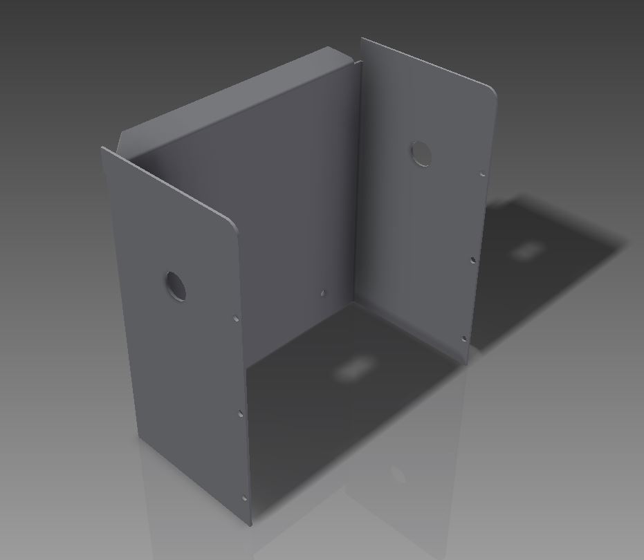
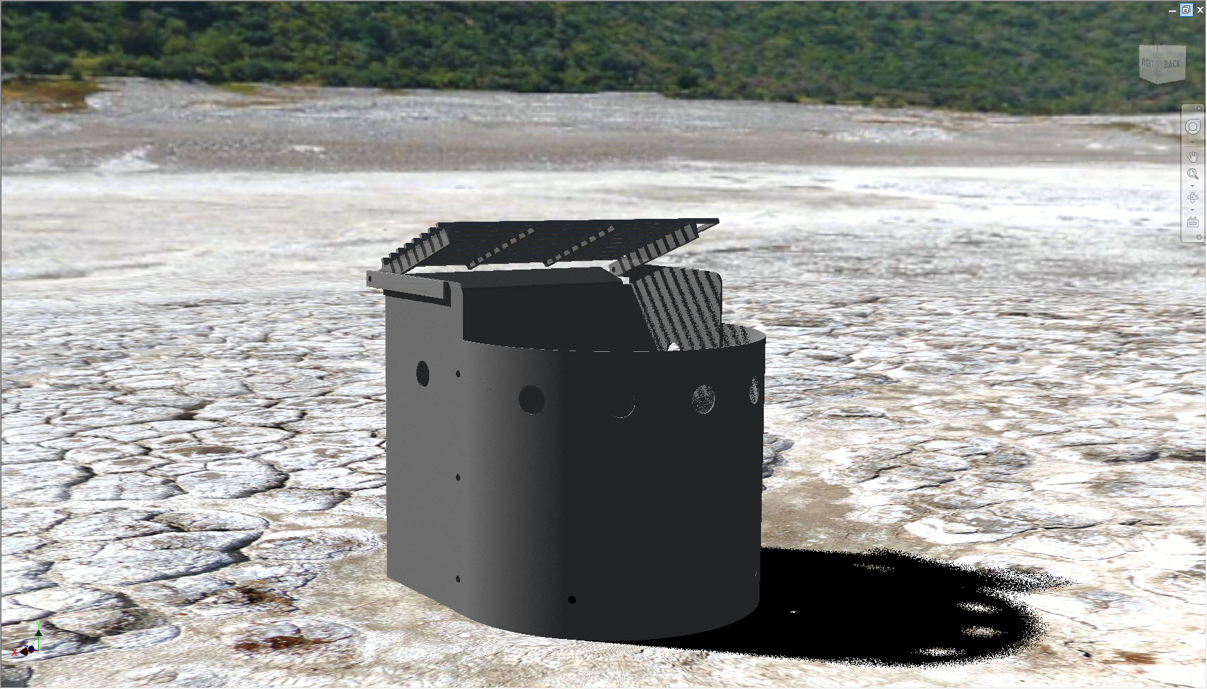
This is an opportunity to show what you know about Inventor. This is not intended to be a fully detailed instruction but more of a road map to get you started a give some direction. This is part 2 of a 6 part project. Please see the attached file for details.
Downloads
Set Up Sheet Metal Styles
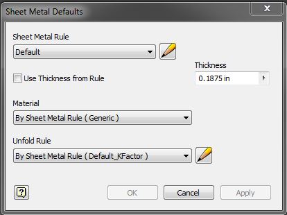
Customize Sheet Metal Styles to suit part.
Create Face
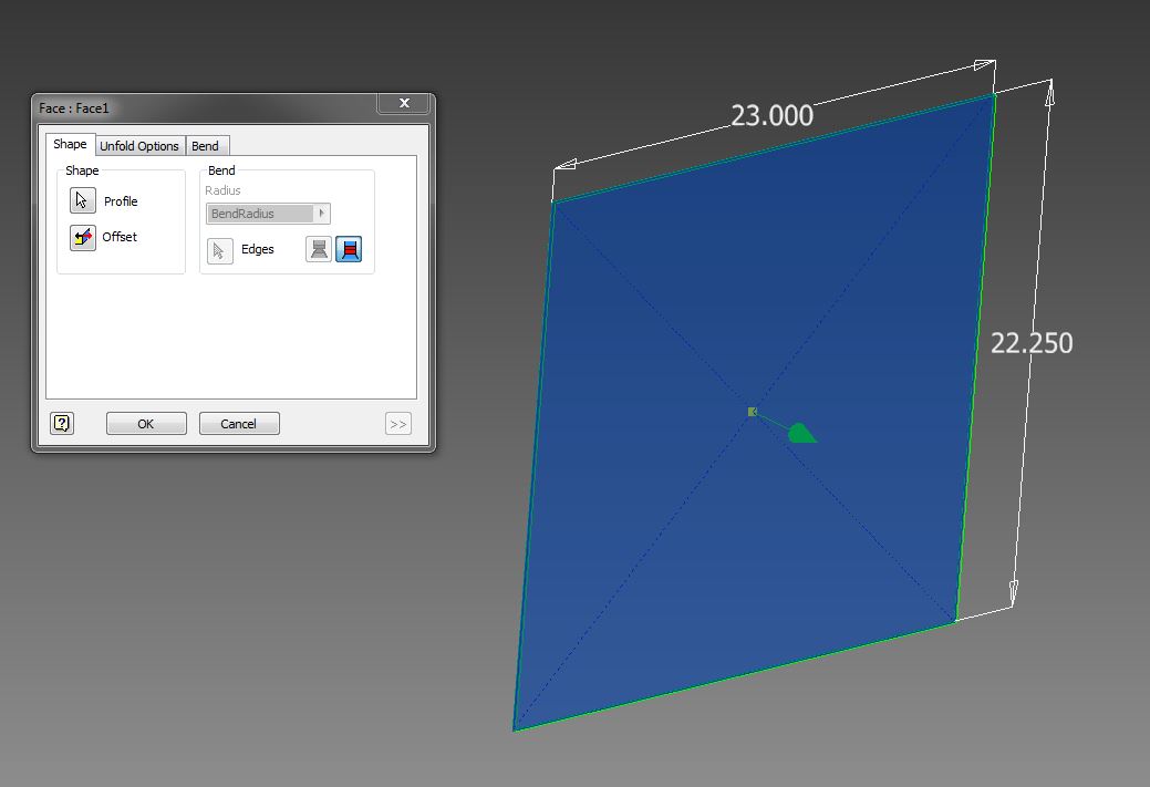
Create a 2D sketch for the back face and use the "Face" commend to create it.
Add a Centered Flange
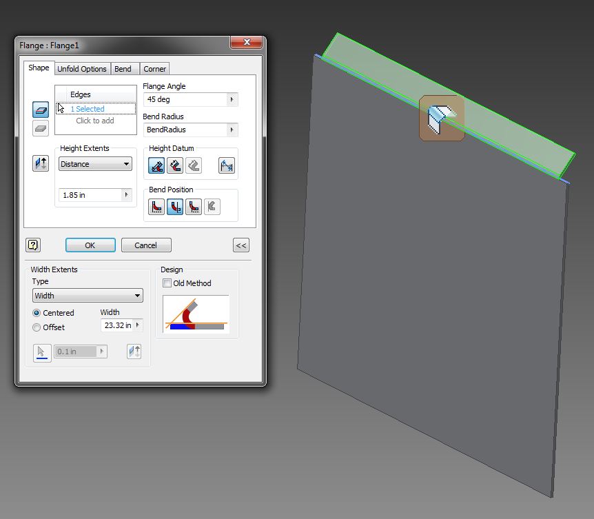
Add a centered Flange to the top edge of the back face, Select the double arrow in the bottom right corner of the flange creation screen to open the additional size refinement and flange placement criteria.
Cut the Tabs Off the Flange
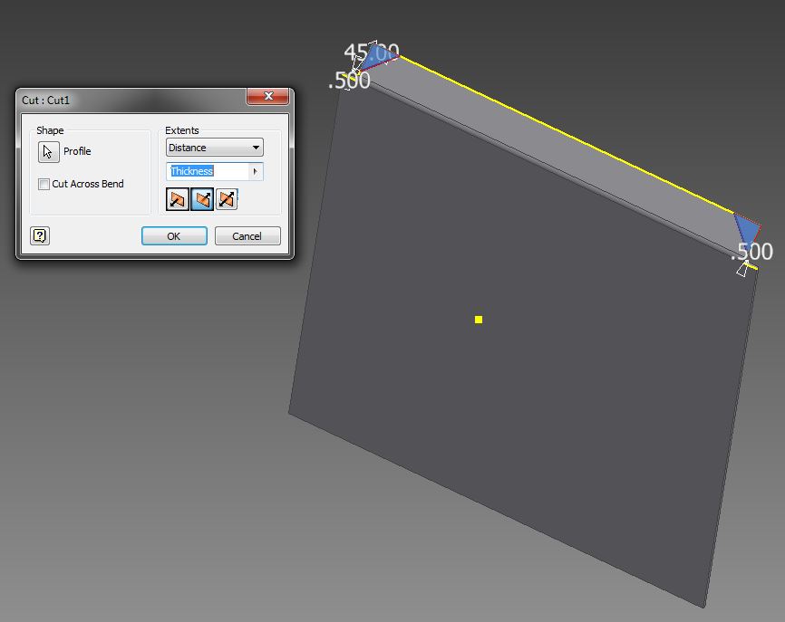
Use the "Corner Chamfer" command or create a 2D sketch and use the "Cut" command to add chamfers on angled flange.
Add Side Flanges
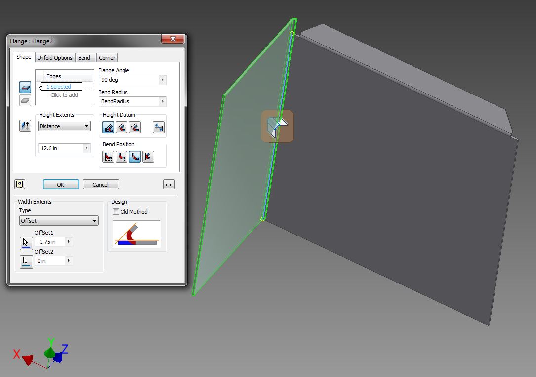
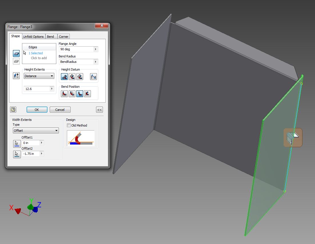
Add side flanges to the back plate. Make sure your flange placement and sizes give you the final dimensions required. Use the "Measure" function for quick checks on distances. To enable "Measure" hit the "M" key or look in the "Inspect" tab.
Create Sketch and Features From Side Flange
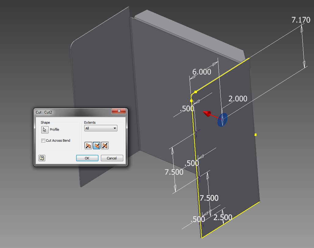
Create a 2D sketch on the side of one of the flanges, create a points set for creating the side holes and create a circle for cutting the large air hole. Once complete use "Cut" to create the large air hole through all.
Create Side Holes
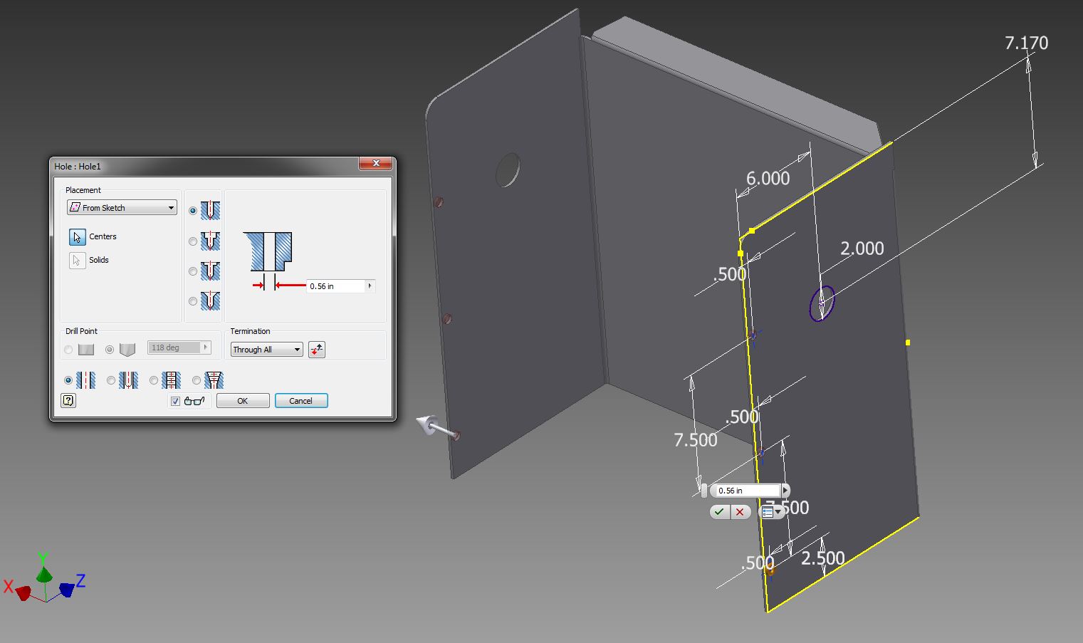
Create the side holes using the "Hole" feature command, through all.
Create the Holes on the Back Surface for the Anchor Bars
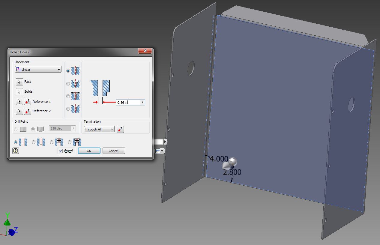
Create the holes on the back surface for the anchor bars using the "Hole" feature and "Linear Placement".
Create Flat Pattern
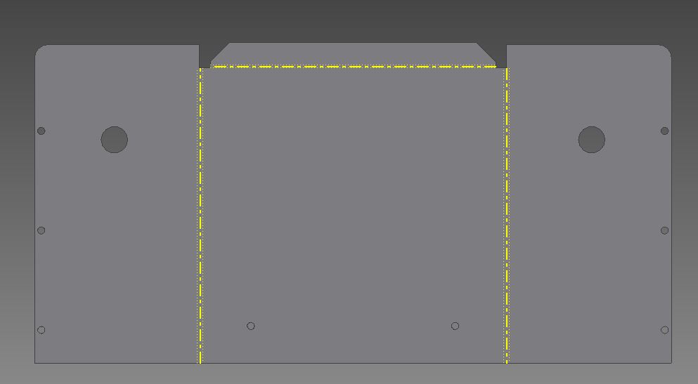
Create a flat pattern of the completed part.