Face Recognition Automatic-Door
by tobias7227 in Circuits > Raspberry Pi
1846 Views, 19 Favorites, 0 Comments
Face Recognition Automatic-Door

This project demonstrates enhanced security and convenience for homeowners by implementing a highly secure, facial recognition-based system on doors. The system uses a camera to verify the homeowner's face, automatically unlocking the door for quick and secure access.
I created this project to address the risks of carrying keys, which can be lost or stolen. Unlike keys, your face is always unique and cannot be misplaced. This project ensures that your home remains secure while making entry fast and effortless.
Supplies
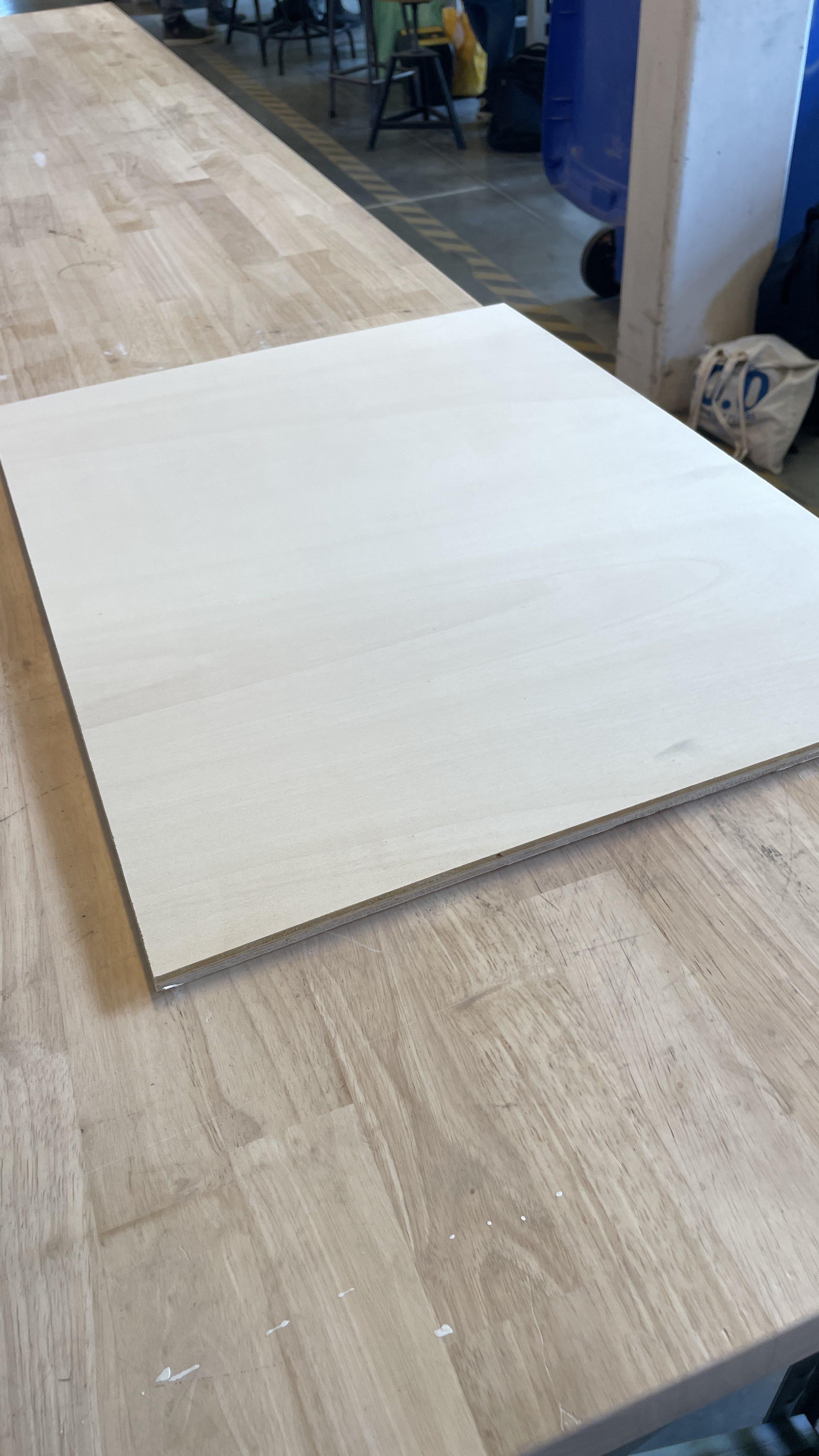
- 2 plywood with the following dimensions: 600 mm x 450 mm x 5 mm.
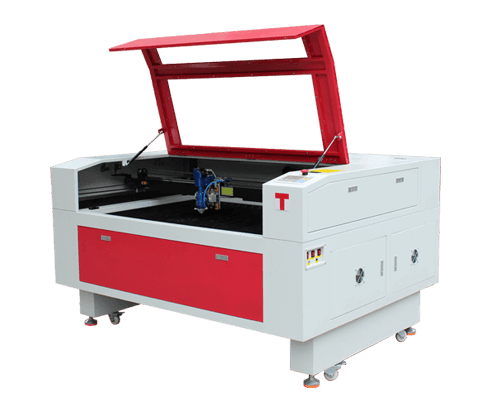
- A lasercut machine
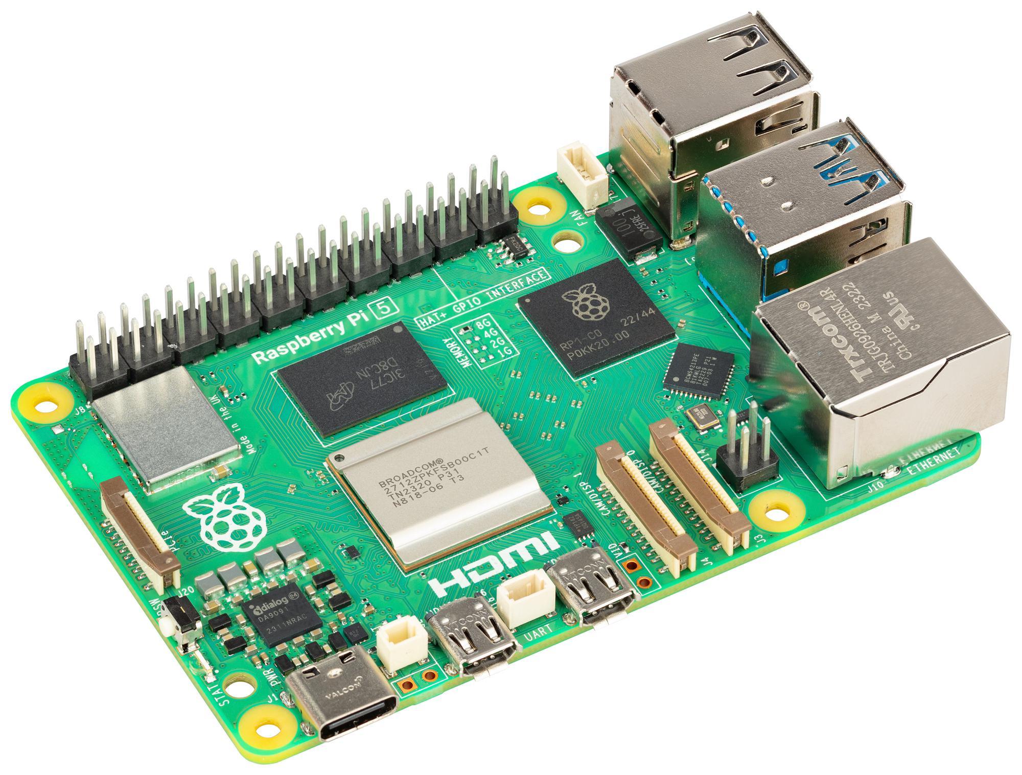
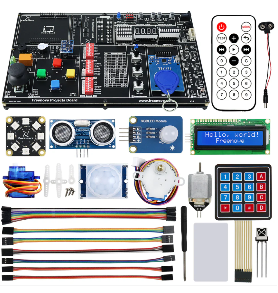
- RaspberryPi with the Freenove Project Kit
- Webcam, can be any webcam/camera. I am using the ASUS ROG Eye S - Webcam
Total Cost: €311
Downloads
Buy Ply-Wood

For this project, you will need to purchase two pieces of plywood with the following dimensions: 600 mm x 450 mm x 5 mm. Make sure to select high-quality plywood that is smooth and free of any major imperfections, as this will affect the final look and durability of your project.
Laser-Cut
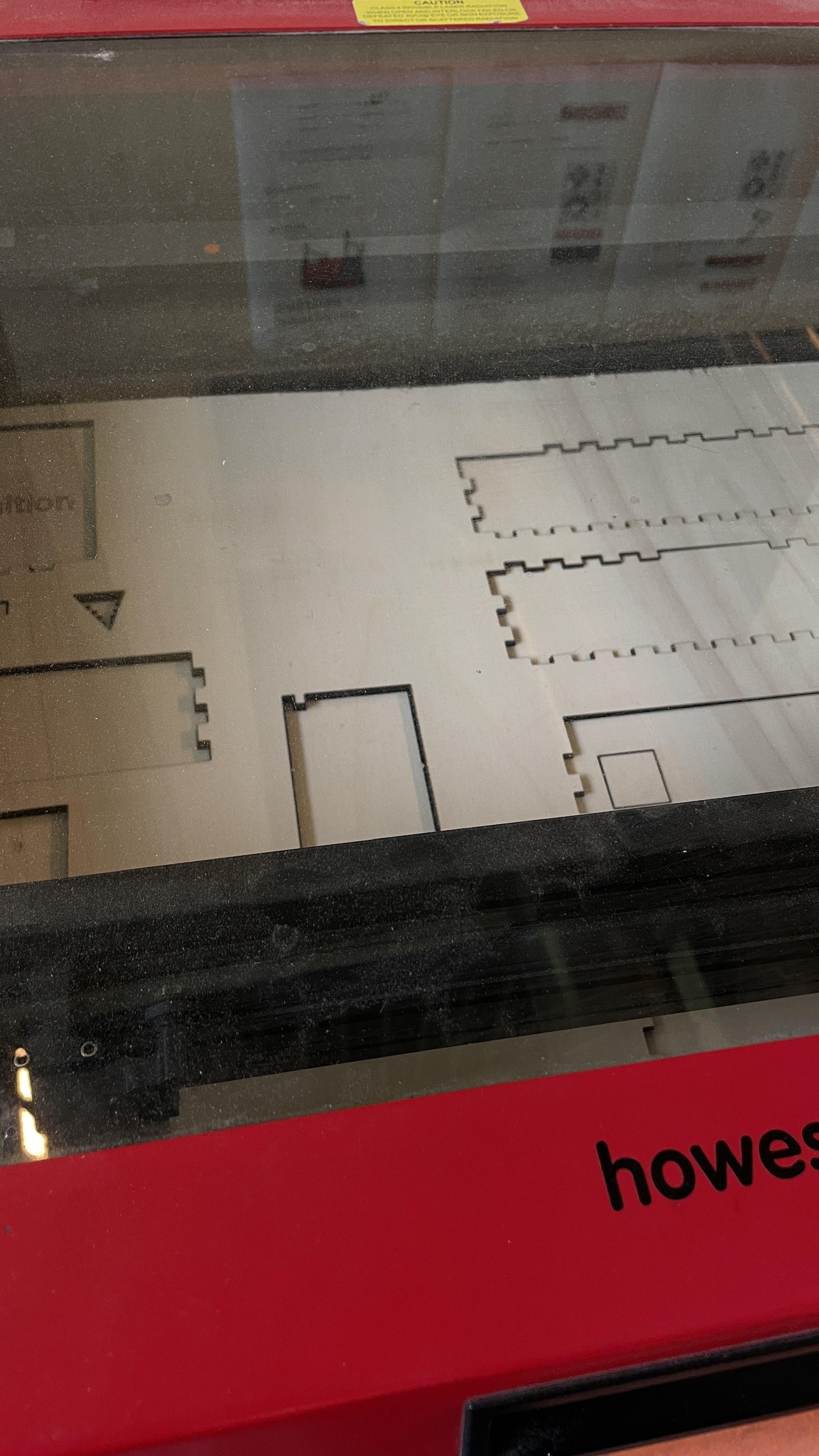
For this step, you will need to laser-cut the plywood pieces using the provided files. Each file corresponds to one of the plywood sheets, and they have been designed to fit the dimensions of 600 mm x 450 mm x 5 mm.
- Prepare the Laser Cutter: Ensure that the laser cutter is properly set up and calibrated. Make sure that the cutting bed is clean and free from any debris.
- Load the Files: Upload the provided files into the laser cutting software.
- Secure the Plywood: Place one plywood sheet onto the laser cutter bed, ensuring it is aligned correctly and securely held in place. Repeat this step for the second sheet after the first one is cut.
- Adjust Settings: Configure the laser cutter settings according to the material specifications. Use the appropriate power, speed, and frequency settings to achieve clean cuts without burning or charring the wood.
- Start Cutting: Begin the cutting process for the first file. Monitor the process to ensure that the cuts are clean and accurate. Once completed, remove the cut piece and load the second plywood sheet to cut using the second file.
- Inspect the Cuts: After both pieces are cut, inspect the edges and surfaces to ensure they meet the project requirements. Clean any residue or debris from the cut edges if necessary.
These steps will help you achieve precise and clean laser cuts for your project components.
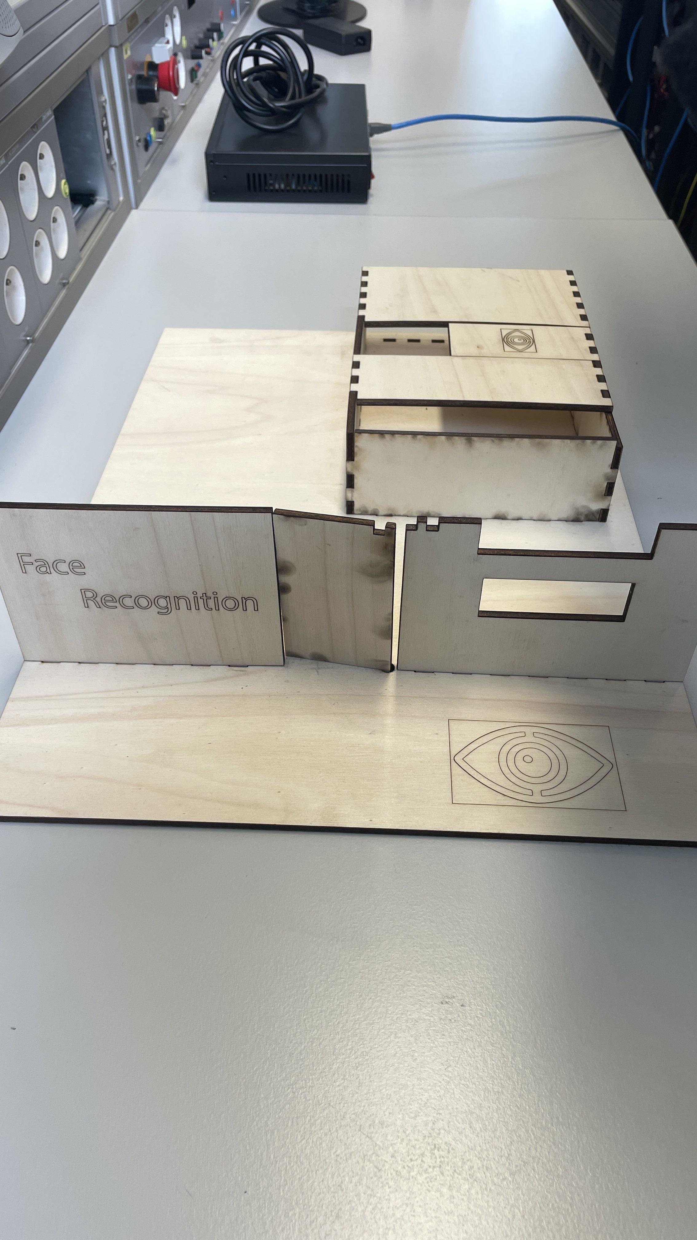
Assemble the Wooden Parts
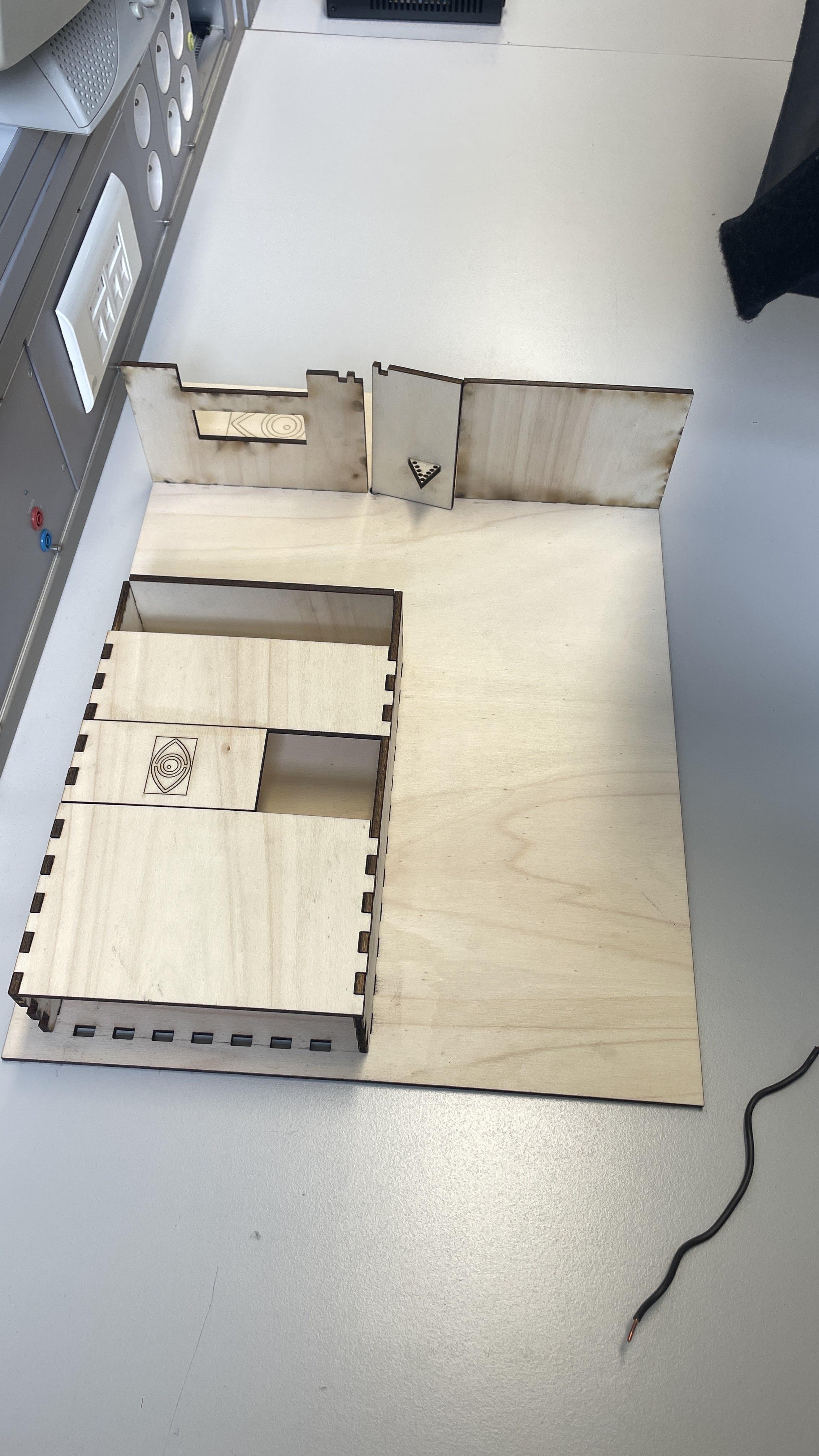
Now that you have your laser-cut plywood pieces, it's time to assemble them. Each piece has been precisely cut to fit together seamlessly.
- Organize the Pieces: Lay out all the laser-cut parts for a better overview. It is pretty straight-forward which parts go where.
- Start with the Base: Begin by assembling the base structure. Fit the corresponding pieces together by aligning the slots and tabs. Gently press them into place until they snap together.
- Secure the Top: Attach the top piece last. Align its tabs with the corresponding slots on the assembled sides. Gently press it down until it fits securely.
- Optional: Reinforce Joints: For added stability, you can apply wood glue to the joints before fitting the pieces together. This will ensure a more durable and permanent assembly. If you choose to use glue, allow sufficient drying time according to the glue manufacturer's instructions.
Your wooden parts should now be fully assembled, forming the intended structure with precise and clean joints.
Glue Wooden Part on Door
Now apply the wooden part on the door with:
- Wood Glue: If using wood glue, apply a generous but even layer of glue on the back of the wooden part. Spread it out to cover the entire contact surface.
- Double-Sided Tape or Mounting Strips: If using tape or strips, apply them evenly across the back of the wooden part, ensuring full coverage, especially around the edges and corners.
- Or any other material you can use to make it sick on the door
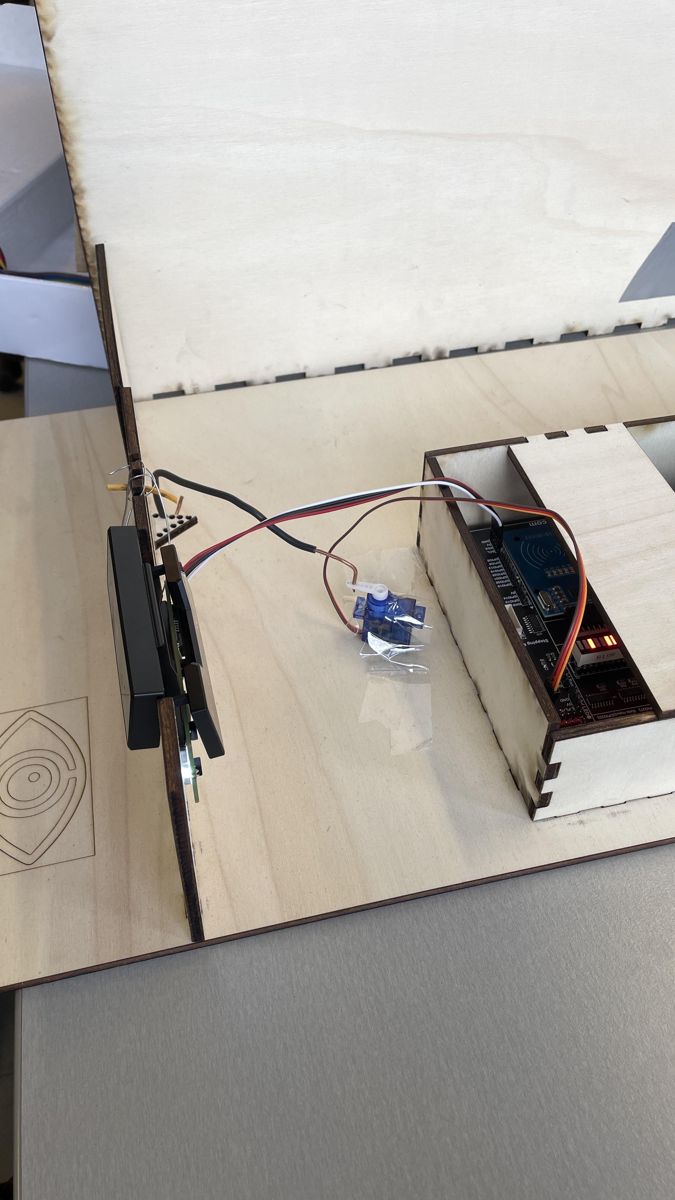
Install Servo Motor
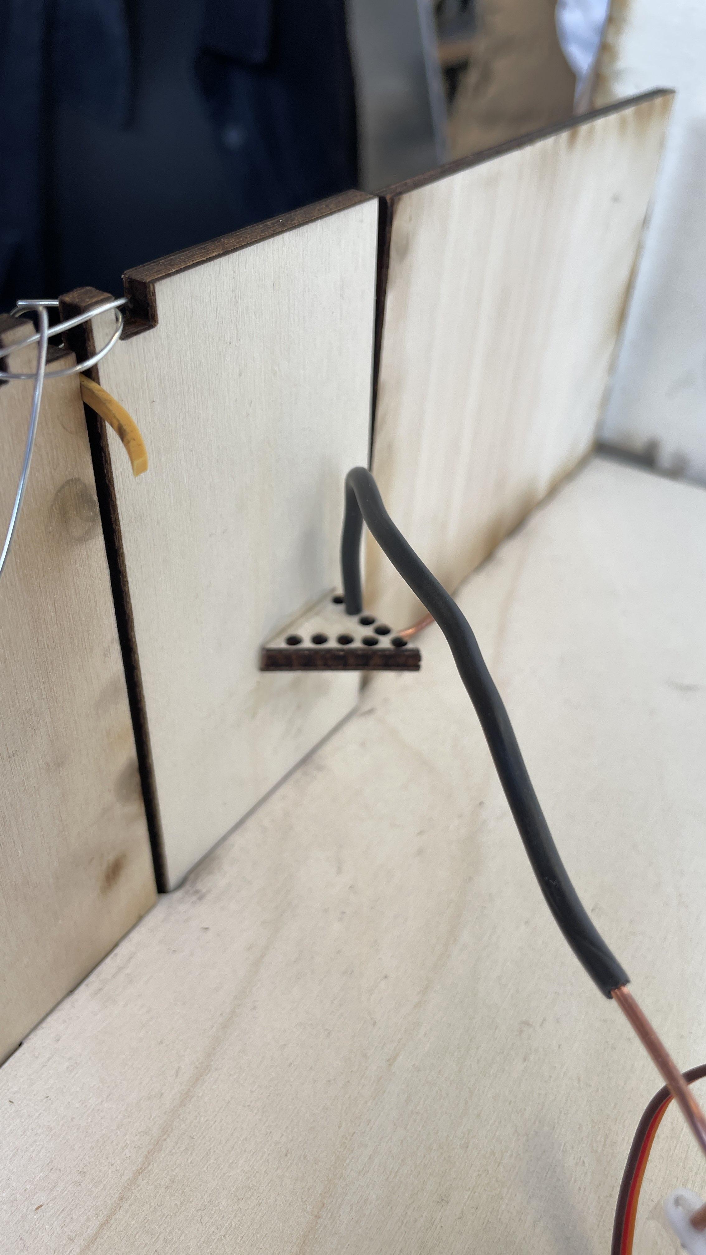
In this step, you will install the servo motor and connect it to the wooden part on the door using a copper wire.
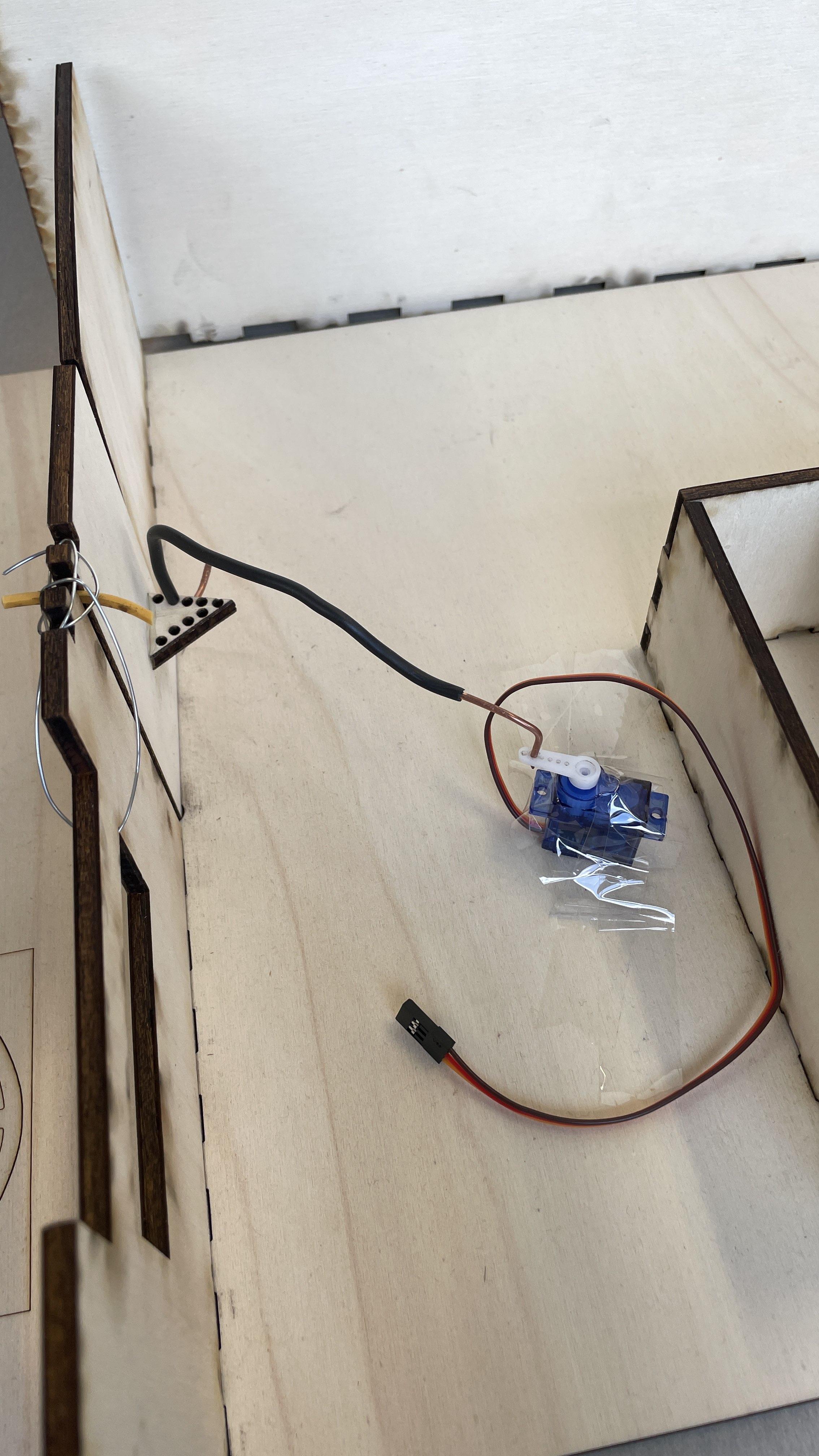
- Position the Servo Motor: Place the servo motor on the ground at an approximately 80-degree angle to the door. Ensure it is positioned in such a way that it can effectively control the movement of the door.
- Secure the Servo Motor:
- Using Tape: If you are using tape, you can use double-sided tape on the bottom, or tape it from the top to the ground with normal tape.
- Using Glue: If you are using glue, apply a generous amount to the bottom of the servo motor and press it firmly onto the ground. Allow the glue to dry according to the manufacturer’s instructions to ensure a strong bond.
- Check Stability: Ensure that the servo motor is securely attached and does not move. This is crucial as the motor will generate movement.
- Connect the Copper Wire:
- Insert one end of the copper wire into the servo motor arm. Secure it tightly so it will not come loose during operation.
- Insert the other end of the copper wire into the wooden part that you previously attached to the door. Ensure it is secured firmly to transmit the motor's movement effectively.
- Test the Setup: Gently test the connection by manually rotating the servo motor arm. Ensure that the copper wire moves smoothly and transfers the motion to the wooden part on the door.
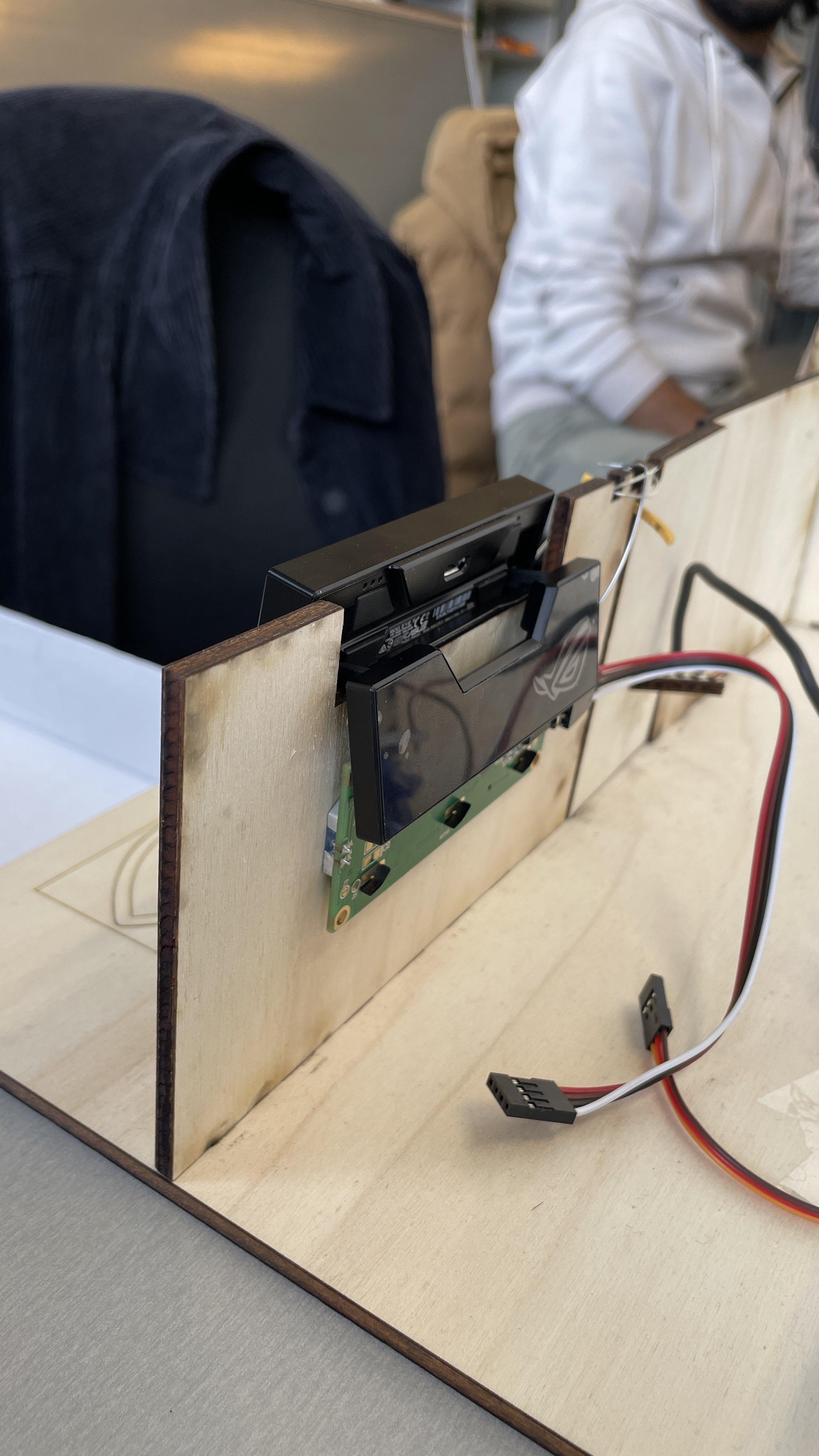
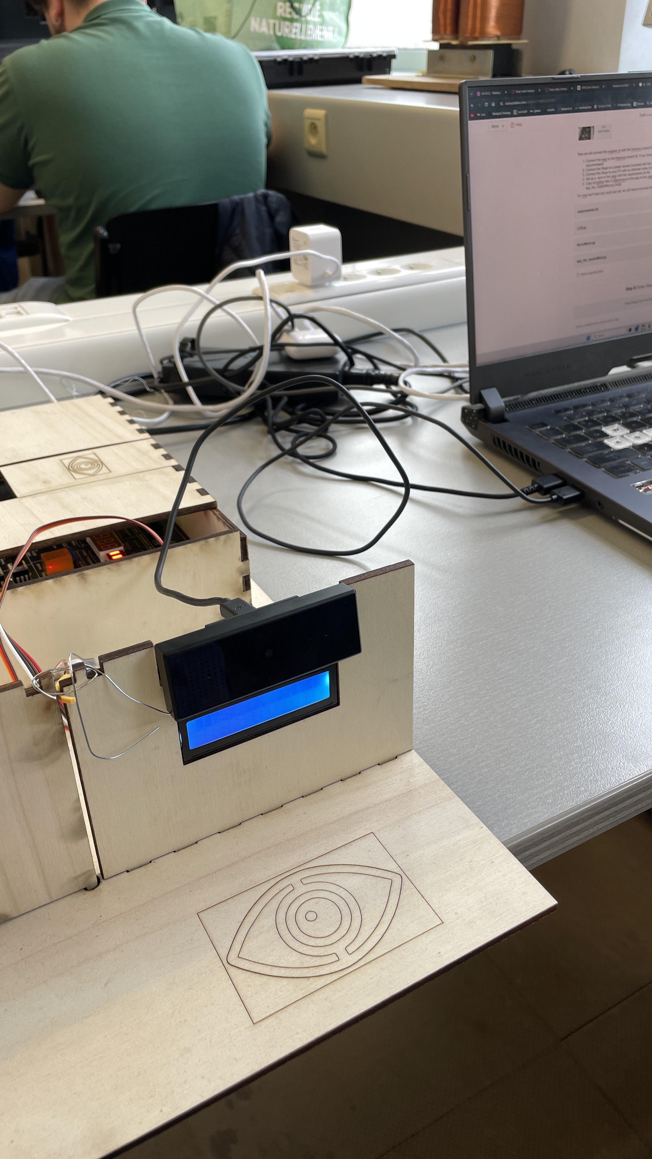
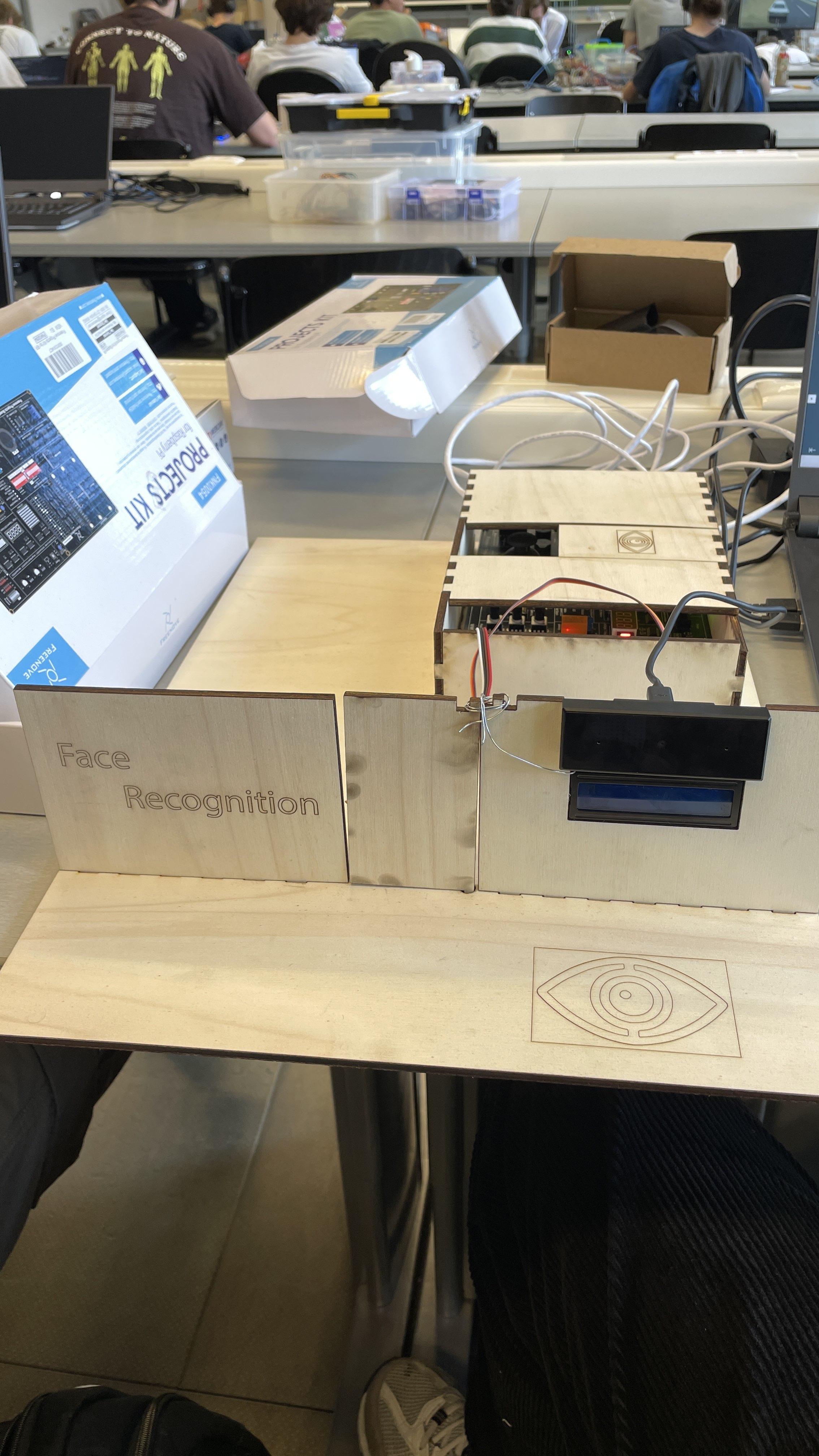
Install the LCD and Camera
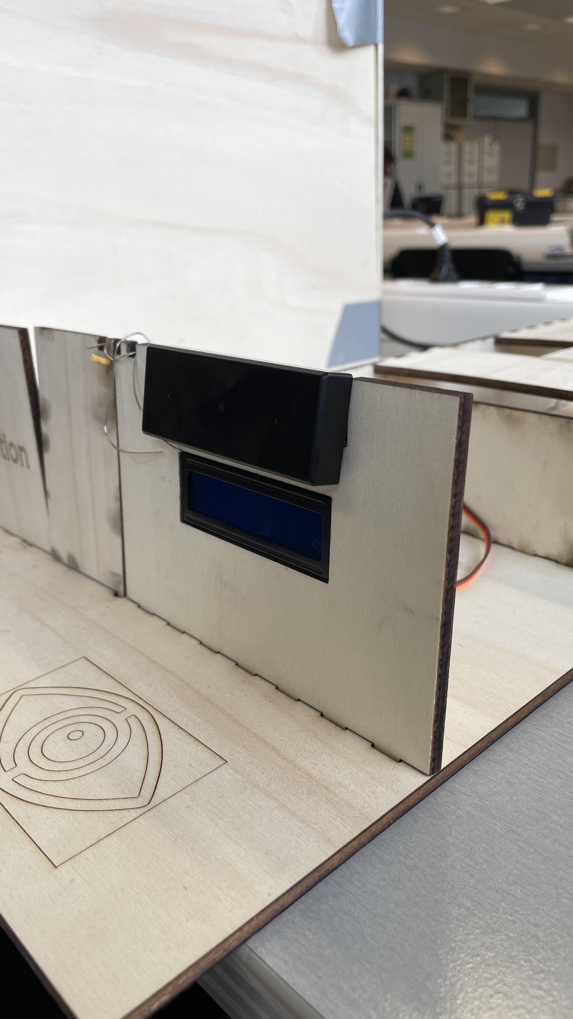
In this step you will place the LCD and Camera on the right wall.
Pretty straightforward:
- Place the LCD in the pre-lasercut hole in the wall. It will fit perfectly
- Place the camera above the LCD also in the hole made for the camera.
Make sure both are secure and sturdy as optimally these would not move.
Connect Your RaspberryPi
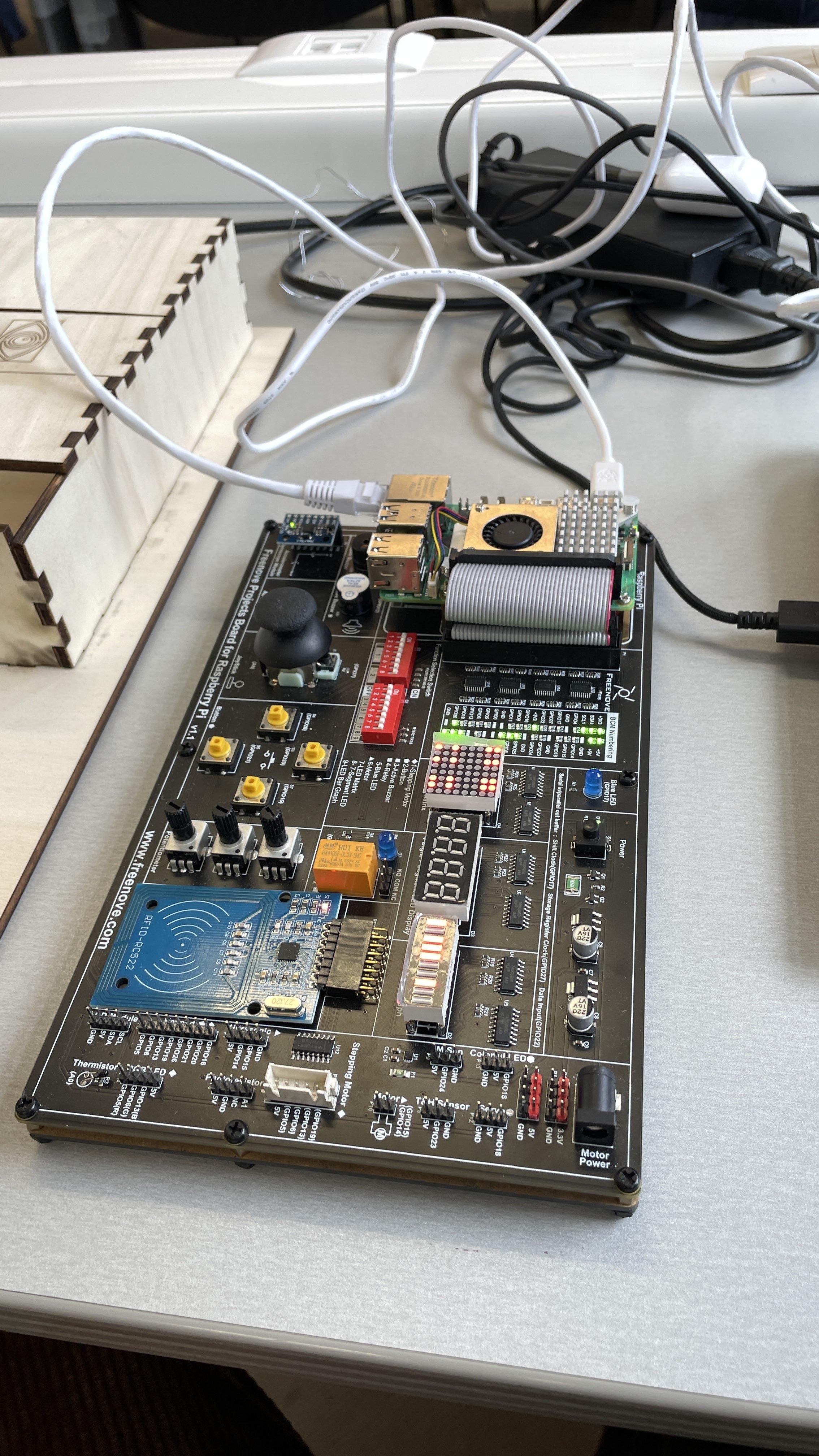
Now we will connect the raspberr pi with the freenove project kit and our PC:
- Connect the raspi to the freenove project kit. If you have trouble with this, please look at the freenove project kit documentation
- Connect the Raspi to a power source (included with the Raspi)
- Connect the Raspi to your PC with an ethernet cable (included with the Raspi)
Setup and Connect Your Project Kit
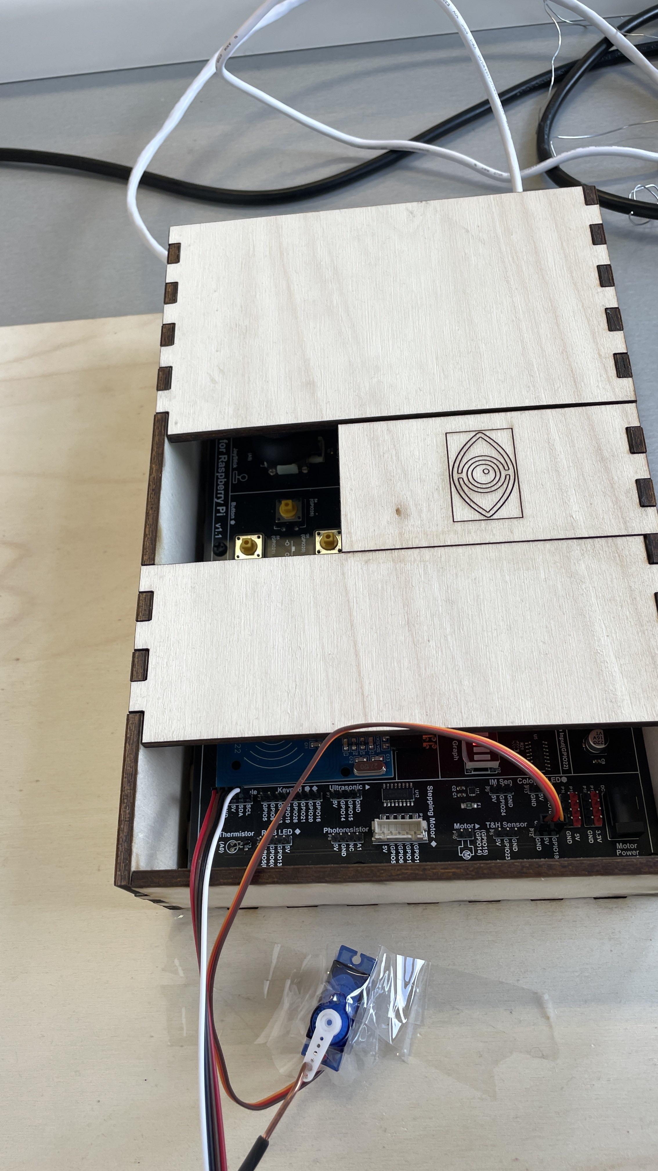
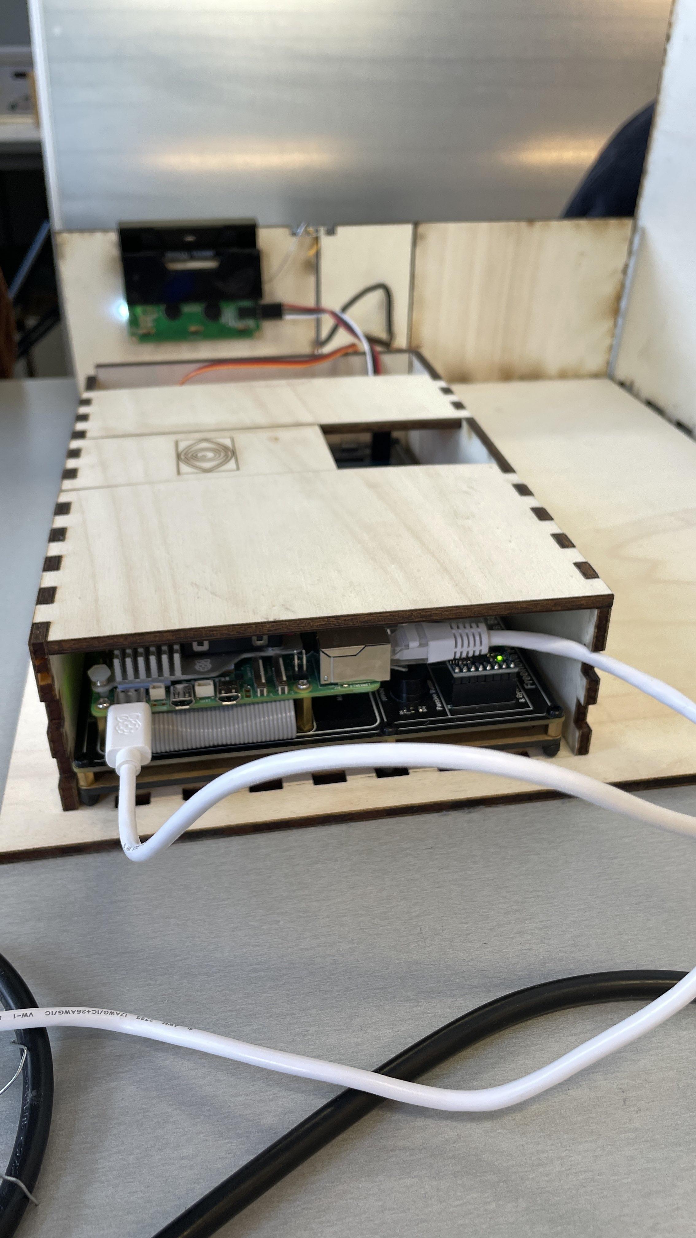
In this step, you will connect the servo motor and LCD to the project kit, and then connect the camera to the PC.
- Place the Project Kit Inside the Box:
- Carefully place the project kit inside the box, ensuring that it fits well and is stable.
- Connect the Servo Motor to the Project Kit:
- Locate the servo motor connection pins on the project kit.
- Connect the servo motor’s wires to the corresponding ports on the project kit. Ensure that the connections are secure and correctly aligned.
- Connect the LCD to the Project Kit:
- Find the LCD connection pins on the project kit.
- Connect the LCD screen’s cables to the appropriate ports on the project kit. Make sure the cables are securely attached.
- Secure the Connections:
- Double-check all connections to ensure they are secure and properly fitted. Loose connections can cause malfunctions.
- Tidy up any excess cables inside the box to keep the setup clean and organized.
- Connect the Camera to the PC:
- Take the camera’s USB cable and connect it to an available USB port on your PC.
- Ensure the camera is detected by the PC and is working correctly.
Start Everything Up
In this final step we will start all the required processes for this to run
- Refer to the GitHub (https://github.com/howest-mct/2023-2024-projectone-ctai-TobiasPottier) for any code needed to run the ai model and connection to the raspi