FPGA Function Generator
.png)
Authors: Nick Mah and Vlad Killiakov.
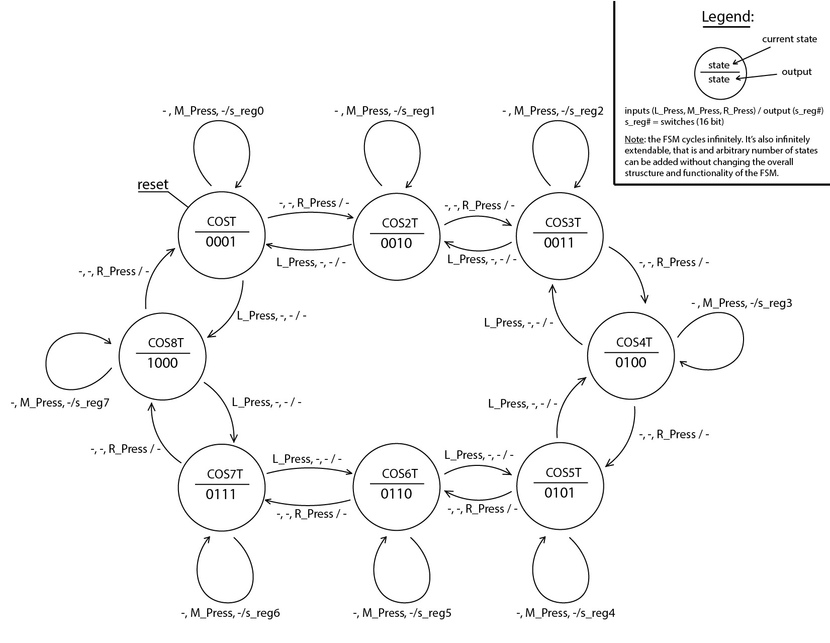
In this project, we will learn how to implement a function generator. Before we start, we should talk about how the project actually works. We will be using 16 switches, 16 leds, 5 buttons and 1 additional pin. The output function is based off a Fourier series that you manipulate using the 5 buttons and switches. There are 8 total sin waves (with different preset frequencies) that you are allowed to modulate the amplitude for. They vary in that their frequencies range from 1-8 times the preset frequency. The switches allow you to set the amplitude of each wave. The left and right buttons allow you to switch between the sin waves with different frequencies (preset values are: sin(t), sin(2t), sin(3t) etc.). The middle button will allow you to apply the amplitude that you selected using switches to the sin wave state (frequency) that you are on.
Intro to Fourier Series Implementation
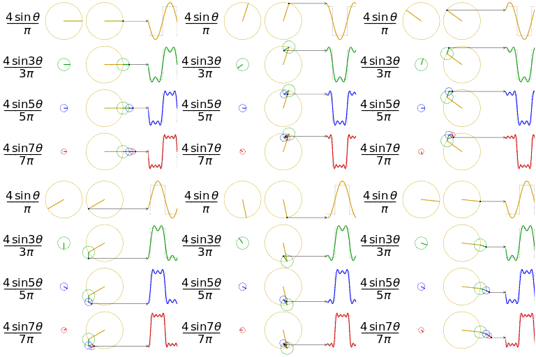
Before we start, I want to give a brief explanation as to how we are using the Fourier series.
The way we are using the Fourier series to generate our waves is that we have 16 different waves, representing 8 unique frequencies and 2 amplitude directions(positive amplitudes and negative amplitudes). We aren't doing FFT or any sort of Fourier calculation. All of that is done by you and inputted into the board using the switches and buttons.
Gather Materials
What you need:
1 - Basys3 Board(Using other FPGA Dev boards or FPGAs in general will work, but you will need to adapt the IO for the code to meet your IO capabilities)
1 - Decade Capacitance Box
1 - Decade Resistance Box
Assorted Wires and Leads(small gauge wire will work best for you)
1 - Oscilloscope (LEDs on the FPGA will also work)
How the Code Works
A Little Bit About How the Code Works:
For those of you who would like to edit the code to suit their needs or have a few additional questions, here's a brief description of how the different project modules work:
General Structure:
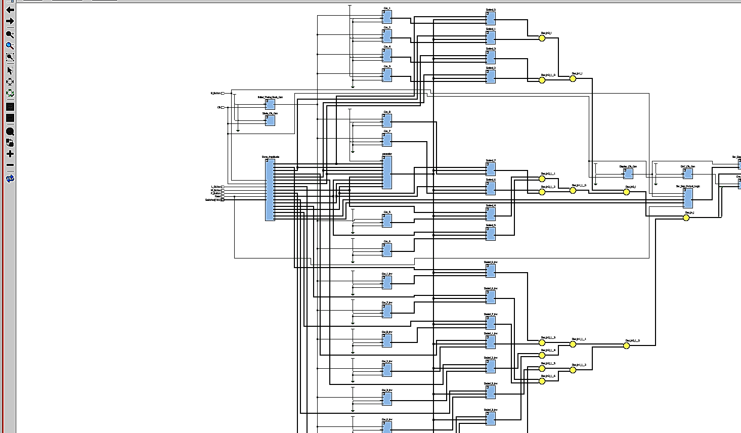
The top module is called "Fourier_Func_Gen". This files declares all of the components and interconnects them together. There are a few modules (Fourier_Register, Disp_Output and Sev_Seg_Driver) that allow the user to see the values of certain states on the seven segment display. The Fourier_register determines when to push the switch values to a register and which register to push to through a FSM. The buttons on the Basys board allows the user to change which register he wants to the set the amplitude of. The value of the sine wave is determined through a large lookup table. The different frequencies of the sine waves before they are added together are pre-determined to be 1,2,3,4,5,6, 7, and 8 times the base frequency. values of the sine waves are calculated, a scaling function multiplies their value with the amplitude stored in the registers that were determined by the the state machine (input by the user). After that, the scaled sinusoid values are added together and pushed to the sigma_delta module. This module uses sigma delta modulation to generate a pulse density function. This value is the end output that you read on the oscilloscope after it passes through a low pass filter. Also, the LEDs on the board light up to represent the value of the summed sinusoids to give a visual representation of the wave if you don't have an oscilloscope on hand.
This next section will go over each individual module:
Fourier_Func_Gen
As mentioned earlier, this is the top module of the design. This file serves mainly to link up all of the other sub-modules together. In terms of processing, this file sums up all of the scaled sinusoids together. Everything else is handled by the other sub-modules within it.
Clk_Divider
This sub-module generates the clock for various files. Currently, there are 4 different clocks, one for the state machine, one for the DAC output, one for the seven segment display and one for the sinusoid base frequency. This module works by adding up a variable every clock pulse, when it hits a divider, the counter resets and a toggle is flipped. This slows down the divides the clock by the value of the divider.
Fourier_Register
This file is one of the most important sub-modules as it holds the main state machine. There are a total of 16 states: 8 for all supported frequencies and another 8 for the same frequencies, but with a negative amplitude. The state machine uses both Mealy and Moore outputs. The Moore outputs are defined within the Fourier_Register module and the Mealy outputs are defined outside the module. This was done to make the code easier to read and make the state machine more obvious.
There is also a code controlling the buttons within the sub-module. This code determines when a button goes from not being pressed to being pressed and sends out a pulse synchronously. This allows the state machine to react to only the change in the button state instead of continuously cycling the button. There is no debouncing on this button. This is because I found that it works without it pretty well most of the time. Adding debouncing would be a good upgrade to this project. Another thing to note is that the buttons need to be pressed two times in order to change to the negative states. This allows me to display the value of the positive and negative state with the same button in order to save IO as well as make it easier to use. The main design decision for requiring a button press to set the register is so that the current value of the registers don't switch while the user is switching through states, which would be very tedious, especially, when you need to skip a register.
Sev_Seg_Output_Logic
This file is pretty simple. It takes the current state of the state machine, the current register that's being edited and a button. When the button is pressed, it alternates between displaying the current state and the current value of the register. This lets the user know which state he is editing and what the current value of the state is. The important thing to note , is that this value is not the current setting of the switches, but the number of the state that the user is on.
Sev_Seg_Driver
This file is a generic display driver file, except that it is also able to display a negative sign. This allows the seven segment display to show when the amplitude is negative as opposed to being positive.
Sigma_Delta
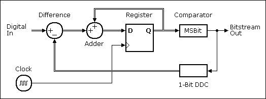
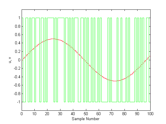
This is another critical file. The sigma delta file turns the current digital value into a sigma delta modulated analog value. The way this works is that there is a very fast loop that runs with a counter. Unlike normal counters, this counter increments itself by a weighted value, which is the current value of the sinusoid. The output of this file is a single bit output that goes high whenever the counter overflows. Thus, the larger the value of the sinusoid, the faster the counter overflows. In essence, this is a pulse density weighted output. We chose to use this type of modulation in order to get a higher frequency response, which isn't actually necessary, but it was more challenging that PWM.
Sincos_Decoder(_inv)
We will cover both decoders at the same time, since they are identical in their structure. Basically, they are both 12 bit long lookup tables with 16 bit outputs. The input is a digital value representing the angle of a sinusoid and the outputs are digital values representing the result of the following expressions: sin(angle) and cos(angle) in 16 bits. The file takes in a clock value and a multiplier. Each clock pulse, the angle increments by the multiplier. This is how we generate the 8 different sinusoid frequencies. This file isn't really a decoder, it's more of a sine and cosine wave generator. However, when this file was created, it was originally a decoder that we pass an angle into and we haven't gotten around to changing it.
Scaler
This file multiplies the amplitude from a register to its corresponding sine wave. It does nothing more and nothing less. Originally, the file used to scale the output value so that there would never be overflow issues in the waveform. However, we decided against doing that due to a large amount of errors with the scaling that was causing the negative waveforms to be canceled out by the positive waveforms, even when they had different amplitudes. Fixing this issue would add a lot more functionality to the project.
Load Code Onto Your Board
Load the bitstream file onto your basys board or use the attached project file to generate your own bitstream.
Setup Your RC Filter

Because the function generator doesn't have a built in DAC, we use sigma delta modulation to create our analog wave. In order to get a nice, smooth wave, you need to filter out the digital portion of your output. Using the decade capacitance box and decade resistance box, we will construct a low pass filter.
- Wire the circuit so that the resistor is limiting current and the capacitor is tied to ground on one end and connected to your DAC output pin and oscilloscope probe. Vin is the signal supplied by the Basys3 board, Vout is the signal read by the oscilloscope.
- Set your capacitance such that it filters out the sigma delta frequency.
- Adjust the capacitance and resistance to get the best waveform.
- The more capacitance you use, the smoother your wave will be. However your wave will also be attenuated more and more as you increase the capacitance.
Enjoy Testing Your Function Generator
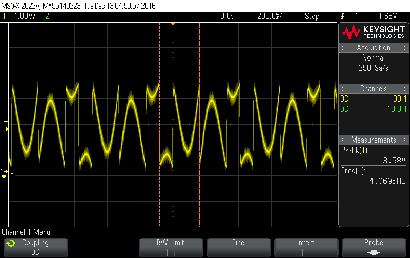
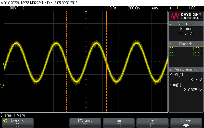
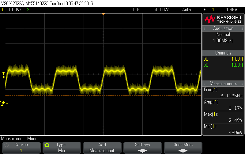
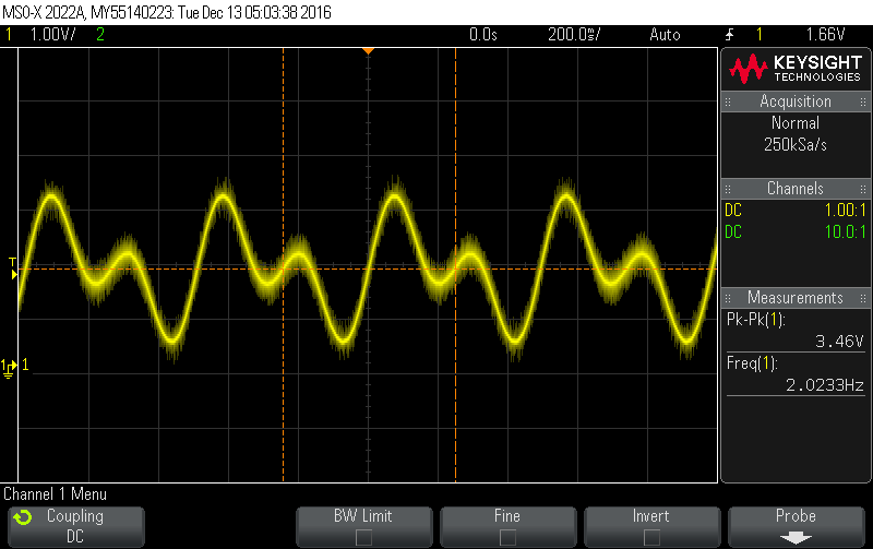
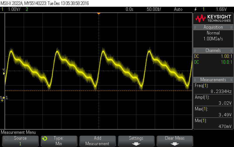
Your function generator is all set up. Because the device only uses the sum of 8 sine waves (and optionally 8 of their negative compliments), your accuracy is pretty poor. However if you would like to use it to power an actual circuit instead of just the oscilloscope, use a buffer to power the real life circuits (to reduce the amount of noise in the signal). The pin on the FPGA cannot supply enough current to get a good waveform if you wanted to power an actual device, that's why you would need to use sort of an amplifier.
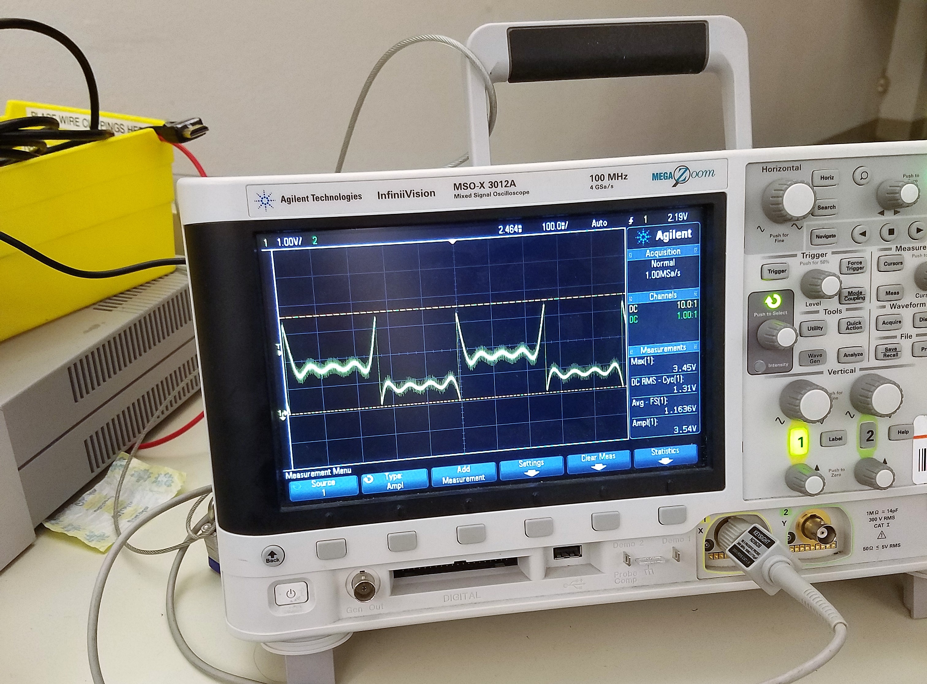
Attached are the images of the different waveforms that were obtained using our Function Generator.
Improvements
As seen in the previous picture, you can tell that there are a few issues with the current setup.
The main problem is that of overflow. As seen in the earlier picture, if our sinusoid overflows, then the wave will continue from the bottom, which is to be expected. However, this obscures the waveform and is pretty annoying. The key to fixing this is to scale the wave such that it never overflows. The best solution I can think of would require detecting what the largest possible value would be and scaling the maximum value to that.
Another big issue is the DC offset. This was a little hard to notice at first, but as we add sinusoids, there seems to be an increasing DC offset that occurs. We are not sure why this happens, but we expect it has something to do with how the sum of the waves is being scaled. Another possible cause is that the sigma delta module needs feedback in order to compensate, which we didn't add.
A third improvement that could be made is adjusting the code such that it is able to handle negative amplitudes without the need for a second, unique lookup table. This could be done in a multitude of ways. The best way we could suggest would be to switch to signed binary.
The final issue is that the source file is really big because of all the lookup tables that were used. This could be fixed pretty easily by multiplexing the waves into a single lookup table. We'd recommend keeping as many copies of the lookup table as you can since it allows you to run at higher frequencies if you desire.
These are the main improvements we can think of currently. There might be some excess code left over from previous iterations and the commenting could definitely be improved, so please let us know of any suggestions you have for improving this project. Thanks for checking it out!