Eye Writer 3.0
This is a new eye writer tutorial
and you can make it at home with arduino
please ignore my grammer mistake
and you can make it at home with arduino
please ignore my grammer mistake
Parts
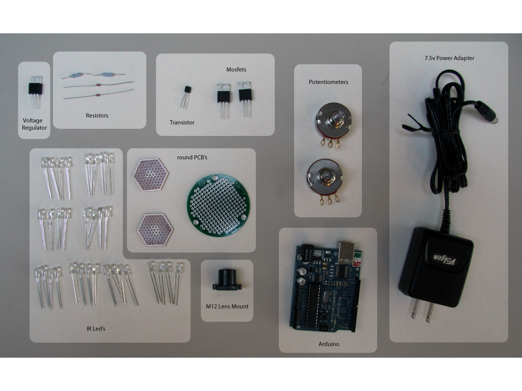
Parts are same as eye writer 2.0
Some Software
The Eyewriter 3.0 requires a few softwere of software for building and running. In this step we will explain how to download and install an IDE, openFrameworks, and the eyeWriter software.
A. Integrated Development Environment pike android (IDE)
An integrated development environment (IDE) is a software application that provides comprehensive facilities to computer programmers for software development.Download and install an Integrated Development Environment (IDE) to run openFrameworks if necessary.
http://www.openframeworks.cc/setup
B. openFrameworks likr c++ librqry
Openframeworks is a c++ library designed to assist the creative process by providing a simple and intuitive framework for experimentation.Download and install openFrameworks if necessary.
http://www.openframeworks.cc/download
C. EyeWriter GitHub this is a software
GitHub is a web-based hosting service for projects that use the Git revision control system. It is a platform that allows people to exchange and share code.Visit the EyeWriter source page on GitHub.
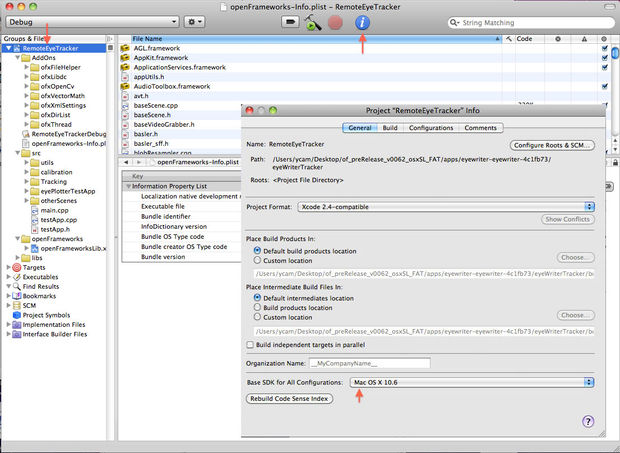
http://github.com/eyewriter/eyewriter/tree/remoteEyetrackerClick Download Source on the top right menu.Choose ZIP format.After download is complete, unzip the file and place the "eyewriter-xxxxxxx" folder into openFrameworks "apps" folder.Open the "apps/eyewriter-xxxxxxx/eyeWriterTracker/RemoteEyeTracker.xcodeproj" file to test that all installations are working correctly. The source code should load in your IDE software.please be sure you're compiling for your current Operating System (the eyewriter software was originally compiled for OSX 10.5 so you might need to change compiling from 'base SDK' to 'OSX 10.6')Build and Run the source code. The Tracking screen should load in video demo mode.
Software - Camera & Arduino
We will also need to install two additional pieces of hardware. Macam will allow our PS3 eye camera to talk to our computer and the Arduino software will permit our physical hardware to communicate with our software.
Installing PS Eye drivers
For Mac:
Macam is a driver for USB webcams on Mac OS X. It allows hundreds of USB webcams to be used by many Mac OS X video-aware applications. Since we are using a PS3 camera, this software will allow our computers to recognize the hardware.
Download the Macam driver from SourceForge.http://sourceforge.net/projects/webcam-osx/files/cvs-build/2009-09-25/macam-cvs-build-2009-09-25.zip/download
After download is complete, unzip the file and place the macam.component file into your hard drives /Library/Quicktime/ folder.
For PC:
download the CL-Eye-Driver:http://codelaboratories.com/downloads/
Arduino
Arduino is a tool for the design and development of embedded computer systems, consisting of a simple open hardware design for a single-board microcontroller, with embedded I/O support and a standard programming language
Download and install the Arduino software.http://arduino.cc/en/Main/Software
Follow the Getting Started tips if you're unfamiliar with the Arduino environment. http://arduino.cc/en/Guide/HomePage
Load Arduino Sketch
In this step you will have to load the Arduino sketch for the PS eye camera to work.
A. Arduino Sketch (Only for PS Eye)
Load the Arduino EyeWriter sketch "apps/eyewriter-xxxxxxx/eyeWriterTracker/StrobeEye/StrobeEye.pde" in the Arduino IDE software. This needs to be done in order that the eyewritter software can recognize the hardware.
With your Arduino board connected, upload the sketch to your board. Follow the Getting Started tips if you're unfamiliar with the Arduino environment.
http://arduino.cc/en/Guide/HomePage
Power Adapter
Power Adapter
In this step you will cut the wire of a power adapter to power your breadboard
Clip off the connector jack of your 7.5 Volt Power Adapter. see image here
Use a Voltmeter to determine the positive and negative wires in the adapters exposed cord.
Using a short strip of red and black wire, solder the red wire to the adapters positive wire, and solder the black wire to the adapters negative wire.
Tape the exposed wires separately to keep positive and negative apart, then tape both together to ensure no wire is exposed.
You Need Infrared Led.s
IR LED's
Gather 8 Infrared (IR) Light-Emitting Diodes (LED) and a small round Printed Circuit Board (PCB).
To build LED arrays on the PCBs youll need to know the positive and negative ends of each LED. Generally speaking the longer leg of the LED is the anode (positive), and the shorter leg is the cathode (negative). see image here
On most LEDs, there will also be a flat spot on the cathodes side of the lens.
From overhead, take note of which direction the wire bond points relative to positive and negative.
Setup a circuit of 4 LEDs in series, in parallel with another set of 4 LEDs in series.see image here Clip the legs of the LEDs and solder them together.
see image here
After soldering the LED legs together to form the circuit, solder about 2 feet (60 centimeters) of the red & green intercom wire to the LED circuits positive & negative ends.see image here
To test the LED PCB panel, build the circuit below. Look carefully to see
Hacking the Ps Camara
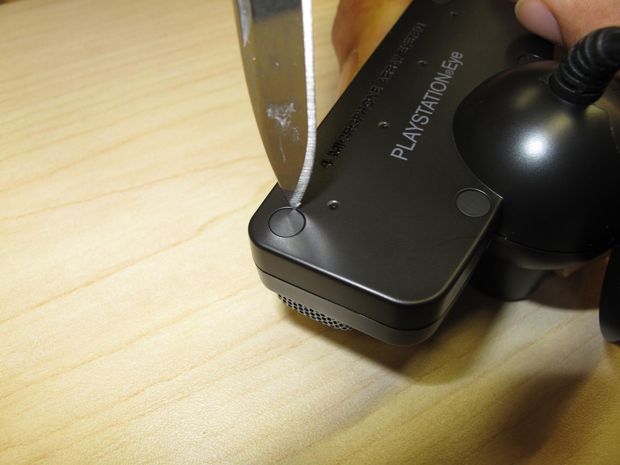
In this step we will talk about how to take apart a PS Eye camera. This is necessary for you to be able to replace the lens on the camera, insert a infrared filter and wire the v-sync.
Get a PlayStation (PS) Eye camera. Use at your own risk because the camera will undergo modifications voiding its warranty.
Pry the four plastic screw caps off the back of the casing. see image here
Unscrew the four screws underneath where the screw caps were. Keep these screws because you will need some later.
With all four screws removed, pry off the back half of the casing. A flathead screwdriver and hammer, or a pair of pointed pliers should work. It requires significant force so be very careful not to damage anything inside or hurt yourself. see image here
Pull the cord aside and unscrew the two bottom screws beside the plastic holder. Keep these screws also. see image here
Remove the stand piece.
Unscrew the five screws around the board (two screws on the side, three screws on top). Keep these screws also. see image here
With all five screws removed, lift the board out of the front casing.
There are four microphones across the top of the board. Using wire cutters, clip off the microphones because they won't be used. see image here
Now the PS Eye board is prepared for wiring. The next steps will connect wiring to the Vertical Synchronization (V-Sync) and Ground joints on the PS Eye board.
Hacking Ps Eye Camara
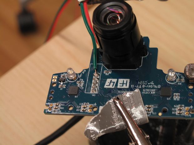
In this step we will go through getting the v-sync off the camera. The v-sync is an electrical signal that comes from the camera which communicates the camera's refresh rate. Getting the camera's v-sync is crucial for this application to work because it is the only way we can match the camera's refresh rate to our infrared LED's.
Locate the Ground joint on your PS Eye board. Some PS Eye models have 5 joints near the lens mount (left image below), while some have 4 joints (right image below). If your model has 5 joints, the Ground joint is at the end closest to the lens mount. If your model has 4 joints, the Ground joint is also at the end closest to the lens mount, and twice as wide as the other joints.see image here
Cut about 2 feet (60 centimeters) of your 4-color intercom wire, and split the red and green from the black and white.
Split the red and green wire about 2 inches (5 centimeters) from one end, and strip off a small section of insulation at the end of the green wire. The green wire will be soldered to the PS Eyes Ground joint.
Clip the PS Eye board and green wire to a stand, and prepare to solder the green wire tip to the Ground joint. Use a piece of thick paper or cardboard in between the clips teeth to prevent scrapes on the board. see image here
Solder the green wire to the PS Eyes Ground joint.
Locate the V-Sync via on the board. Its the via circled in the image below. see image here. Attention: for more recent models of the PSEye camera (identified by the golden rim around the board) the VSync hotspot can be found on the front of the PCB, directly above the R19 resistor. see image here. Very REcently a newer model was also introduced in the market (v9.2)see how to identify it in this image and how to find the vSync spot in this image
Using a sharp knife, carefully pivot the knife tip on the via, and scrape off enough insulation coating to expose the metal contact below. see image here
The red wire needs to connect to the exposed V-Sync via, but the wire is too thick to be soldered neatly to the small via, so a 30 gauge wire will be used in between. Strip the ends of a 2 piece of 30 gauge wire.
Shorten the red wire, then solder one end of the 30 gauge wire to the end of the red wire. see image here
Before soldering the 30 gauge wire to V-Sync, a test should be performed to ensure all connections are correct. Build the circuit below. When the 30 gauge wire contacts the V-Sync via, the LED on the breadboard should flicker rapidly. see schematic here
Using thin 0.022 inch (0.56 millimeters) solder, carefully solder the 30 gauge wire to the exposed V-Sync via. To confirm, ensure the LED on the breadboard is flickering.
Hacking Ps Eyecamara Finishing
In this step we will talk about how to put your camera back into one piece.
Unscrew the 2 screws holding the lens in place. Be careful not to break the fragile V-Sync connection. Detach the lens and keep both screws. see image here
Measure the square opening of the new lens mount. Cut a square from the filter sheet that is minutely smaller, and place it into the lens mount opening.see image here
With the filter in place, screw in the new lens mount. This will require some force, and one screw will go in at an angle because the new lens mount is a little too big for the board. see image here
Screw the new lens into the new lens mount on the board.
Use hot glue to cover and secure the V-Sync connection. see image here
Full Circuit
In this step we will show how to put together the circuit on the breadboard. This is the initial step to getting your Arduino to work with the eyeWriter software.
Build the circuit in the schematic below. see schematic here
After assembling the full circuit, the EyeWriter code is ready for live camera input. To switch from video demo mode to live camera mode, open the "apps/eyewriter-xxxxxxx/eyeWriterTracker/bin/data/Settings/inputSettings.xml", and edit the mode tag from 1 to 0.
Open the "apps/eyewriter-xxxxxxx/eyeWriterTracker/RemoteEyeTracker.xcodeprof" file, and Build and Run the source code. The Tracking screen should load wit
USING EYE Wariter Softwere
In this step we will take you around the eyeWriter software so that you can set it up.
Focus your camera by selecting Focus Screen on the first tab of the Computer Vision (CV) panel on the right. Rotate the lens of your camera until both video feeds look sharp, then deselect Focus Screen to return to the Tracking screen.
see image here
Select load video settings on the first tab of the right panel.
see image here
For PS3 Eye Camera:
Ideally you want a bright, balanced image with minimal noise. An example image is shown below. Under the Webcam tab, slide the Gain and Shutter settings back and forth until the video looks ideal.
Under the Compression tab, if youre using a faster computer set your Frames per second (Fps) to 30. If youre using a slower computer set your Fps to 15.
In this step we will go through the calibration setup.
Press spacebar for instructions, then spacebar again to start. Look at the red dots as they appear.
At the end of the calibration, the blue lines show any calibration inaccuracies. If there are any long blue lines, reset the calibration and press spacebar to start again.
Stare at the Catch Me box. As you stare, the boxs color will turn green.
When the box is fully green, it is caught and will appear somewhere else. Keep catching the boxes to test your eye-tracking calibration.
Keep Advantage and Jealouse Friends
LETTER DRAWING
Drawing mode starts paused by default. Before you start drawing, you can toggle the background grid on or off. The background grid can be toggled at any time by pausing.
To start drawing, switch to recording mode by staring at the paused button. As you stare, the button will turn green and switch to recording.
Drawing works with vector points. Stare at a place on the canvas for about a second to make a point. Your green eye-tracking circle needs to stay very still to make a point.
As you add points, they will stay connected by a stroke. You can create shapes and letters with these strokes. To make a new line, stare at the next stroke button.
To change what you are drawing, you can undo point which removes the last point drawn, or undo stroke which removes the entire last stroke drawn.
To save the current shape or letter and move on to the next one, stare at next letter. Your recently drawn letter will appear at the top of the screen, and you have a new blank canvas to draw a new letter on.
When you are finished drawing shapes and letters, stare at NEXT MODE to move on to Positioning mode.
POSITIONING
By default, all your letters are selected and ready for positioning. You can select individual letters by staring at Select Letter.
Select Rotate allows you to rotate your selection right (clockwise) and left (counter-clockwise).
Select Shift allows you to move your selection up, down, left and right.
Select Zoom allows you to zoom out and zoom in which shrinks and enlarges your selection.
Auto Place will place your letters side by side in the order you drew them.
When you are finished positioning your shapes and letters, stare at NEXT MODE to move on to Effects mode.
Step 17: Using EyeWriter Software - Typing
Stare at whichever key you wish to press. As you stare, the keys color will turn green then flash blue.see image here
When the key flashes blue, it has been pressed. You can see what youve typed at the top of the screen.
To speak the words typed, press the SPEAK key on the bottom left of the screen. On the middle right of the screen, SPEAK WORDS OFF/ON toggles the option to speak words automatically after they are typed and a space is entered.
Note the CAPS OFF/ON key on the bottom right of the screen. This toggles caps lock on and off, and is required to use the alternate characters on the number keys (! @ # $ % etc)
The goal is to block the ball from passing your paddle at the bottom of the screen.
The paddle will slide aligned with the x-position of your gaze. So you can stare at the moving ball and the paddle will slide horizontally in tandem.see image here
I made it but i say honestly i made it before
but i don't
have this project so i use text and pictures of old eyewriter please vote me????