Eye-Following Portrait With Raspberry Pi Pico
by just_another_person in Circuits > Microcontrollers
1183 Views, 15 Favorites, 0 Comments
Eye-Following Portrait With Raspberry Pi Pico

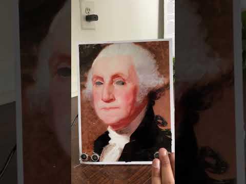
This project uses ultrasonics, as well as a servo motor, to make the eyes of the portrait follow you as you walk past.
Through it's (very) late for Halloween, this project serves as a fun decoration for your house (or a prop to scare unwarned guests...), and can be easily made and assembled in 1-2 hours. Originally, I got the idea for making this from watching some movies with similar ideas (such as Harry Potter), and wanted to create something that resembled that.
With this project, you'll never get rid of the feeling that someone is constantly watching you :)
Supplies
Circuit:
- 1x breadboard
- 1x Raspberry Pi Pico
- 2x Ultrasonic Sensor
- ~4x male-male jumper wires
- 8 male-female jumper wires
- 1x servo motor
- USB cord
Craft:
- Foam core/Cardboard
- Printed portrait + eyes (The PDF to the one I used is linked below)
- Paper
- Straw
- Wire
Tools:
- Exacto knife
- Hot glue gun
- Tape
Downloads
Cut Out the Original Eyes


Using an exacto knife or a sharp pair of scissors, cut out the eyes from the portrait. Then, cut a carboard or a foam core board of the same dimensions, as well as a rectangular hole (around 6x1 inches) centered around the same area that the eyes are positioned on the portrait. Glue the paper onto the board, making sure the edges are aligned.
Adding the New Eyes


Cut a small piece of paper, slightly shorter in length, but wider than the hole in the board (around 5x3 inches-- reference the first image above). Center it over the hole, making sure it goes over the eye holes.
Flip the board over, and mark a dot on the area where the paper meets the side of each eye (image 2). It should look as if the person in the image is looking to the right.
Taking the paper out, glue the eye cut-outs (linked with the pdf in the material section) onto the markings you made. Now, if you move the paper from side to side, it should look like the portrait's eyes are moving.
Paper Slot

Now, using the paper with the new eyes made in the previous step, cut out a slightly larger piece of paper (around 1 inch larger in dimensions), and align it over the smaller piece, gluing or taping the edges down. Then, using hot glue, secure the paper surrounding the smaller sheet, so it fits snugly in, but has room to slide in and out without too much difficulty.
Servo Moving Mechanism


Cut a small piece of a straw, and pull a wire through it. One end of the straw should be taped/glued to the card with the eyes along with an end of the wire, and the other should have a bit of wire (around half an inch) extending out to the other side (image 1).
Separately, take ~2 inches of carboard, cut into a half-inch wide strip. Glue it vertically near the paper slot, with the servo motor on top (image 2). This will become the stand for the servo motor, to prevent it from bumping onto the board when it turns.
Take the wire extending out of the straw, and wrap it around one of the servo attachments, securing the connection with glue.
Now, when you turn the servo, it should also move the eyes in a linear motion from side to side.
Circuit


This circuit uses Raspberry Pi Pico, as well as two ultrasonic sensors and a servo. A pinout diagram is attached above for reference.
*When referring to the pin connections in this step, I am referring to the physical numbers of the pins on the board*
Ultrasonics:
Add male-female jumper wires to the end of the ultrasonics, to connect it to the breadboard.
VCC: both ultrasonics connect to the VBUS (pin 40)
TRIG: For Ultrasonic #1, I connected it to GPIO 2 (pin 4). For Ultrasonic #2, it was connected to GPIO 4 (pin 6).
ECHO: For Ultrasonic #1, I connected it to GPIO 3 (pin 5). For Ultrasonic #2, I connected it to GPIO 5 (pin 7).
GROUND: use any available ground pin (Pin 3,8,13,18, ect.)
Servo:
First, add three male-male jumper wires to the ends of the wires, so they can be connected.
VCC: connect to VBUS (pin 40)-- [if there isn't enough room, connect the pins going to VBUS to the positive or negative rail. Then, use a single jumper wire to connect that rail to VBUS.]
GROUND: any available ground pin
SIGNAL: use a GPIO pin. I used GPIO 15 (pin 20).
Inserting Sensors


Cut out holes for the sensor on either side of the portrait, and tape them into place. Then, glue/tape the breadboard into the center of the board, making sure that it isn't straining any connections
If you want it to have a wider range of detection, you can add extensions on either sides of the picture frame, and connect the sensors to that as well.
Code
Code: https://github.com/just-another-person1/Projects-/blob/main/Object%20Following%20Portrait
Here's a quick explanation of what the code's doing:
1) Imports + Pin setups:
time & sleep-- sleep is used to delay the execution of part of the program for a given amount of seconds
Pin, PWM (Pulse Width Modulation)-- useful for controlling the amount of power delivered the output. Since we're also importing Pin, it means we refer to the pins while setting up by their GPIO number rather than pin (board) number.
math-- to preform basic math functions in the code
2) Servo & Ultrasonic connections: Refer to the GPIO connections made in the steps above, and modify the outputs for any changed pins.
At the start, we also set the servo so that the eyes are pointing towards the middle (line 17).
3) Distance Functions: The ultrasonic sensor sends an ultrasonic wave, which is then reflected back by nearby objects. This function times how long it takes for the sensor to send and receive the waves, and then uses the distance formula (distance=speed/time) to find how far the waves went. It divides that distance by two to only measure the distance the wave takes reaching the object.
For this code, since we have two ultrasonic sensors, we use two different functions, with distance #1 being for the ultrasonic on the left, while distance #2 is for the right.
4) While True loop: If ultrasonic #1 detects an object less than 40 cm away, it signals the servo to turn left (as the obstacle is on that side). If ultrasonic #2 detects an object less then 40 cm away, it moves to the right.
Stand


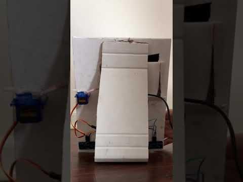
Glue a piece of carboard to the back of the board (reference the image above), making sure that it does not strain the circuit.
Now, your project is done! Run it by either keeping the USB connected to the computer, or to a power outlet.