Extendable Handheld Gimbal for GoPro/SJ4000/Xiaomi Yi/iLook
by MithilR in Circuits > Cameras
3811 Views, 39 Favorites, 0 Comments
Extendable Handheld Gimbal for GoPro/SJ4000/Xiaomi Yi/iLook
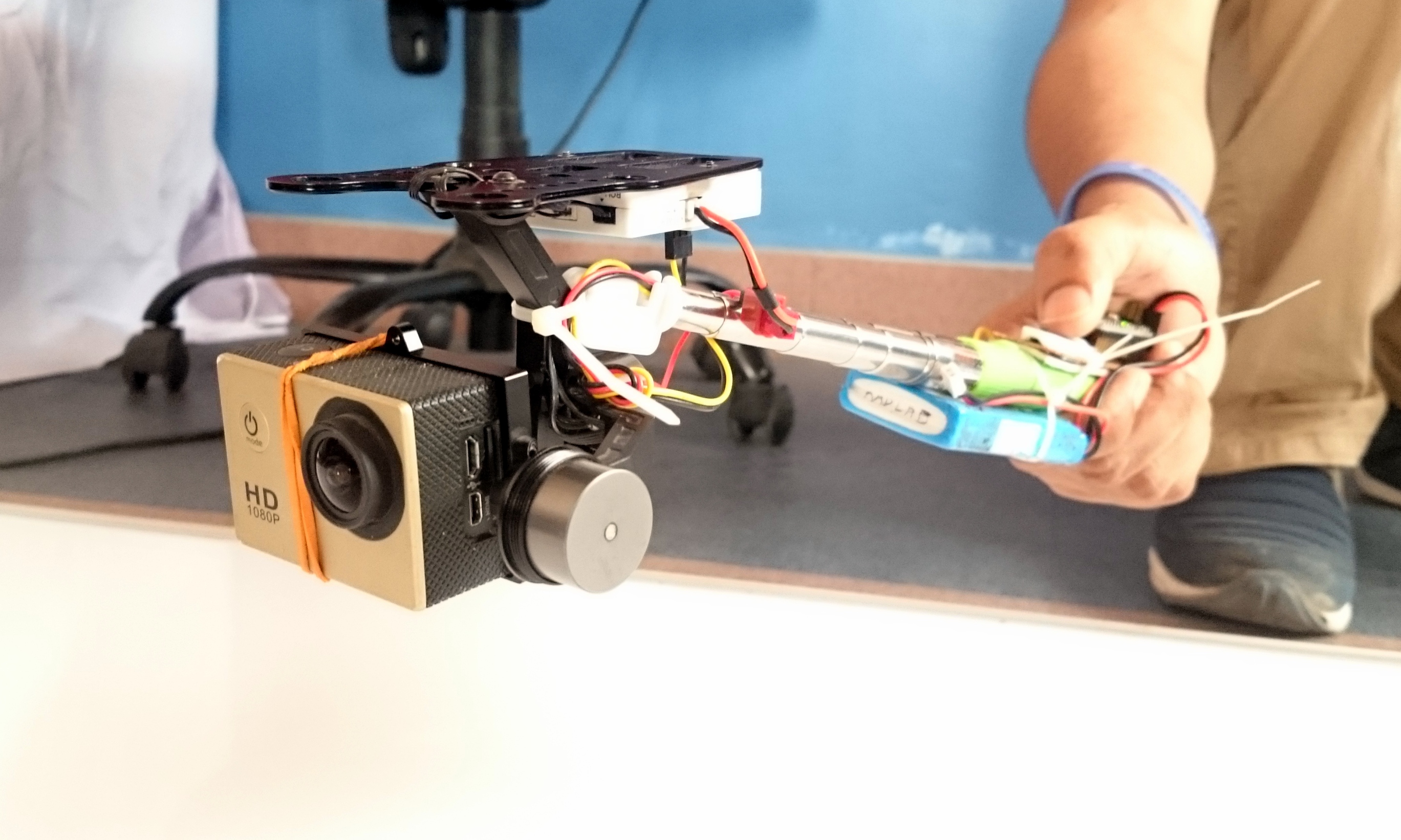
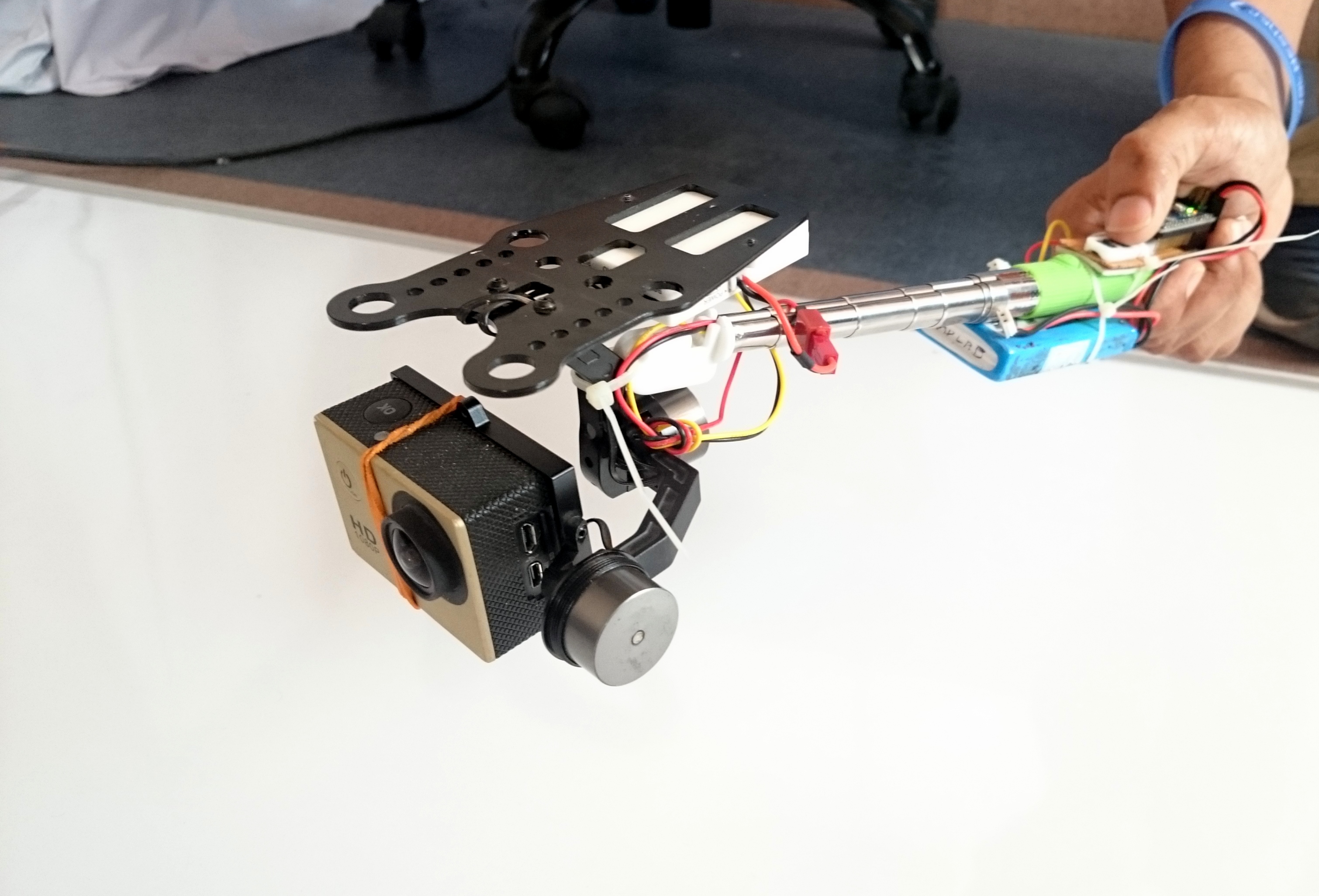
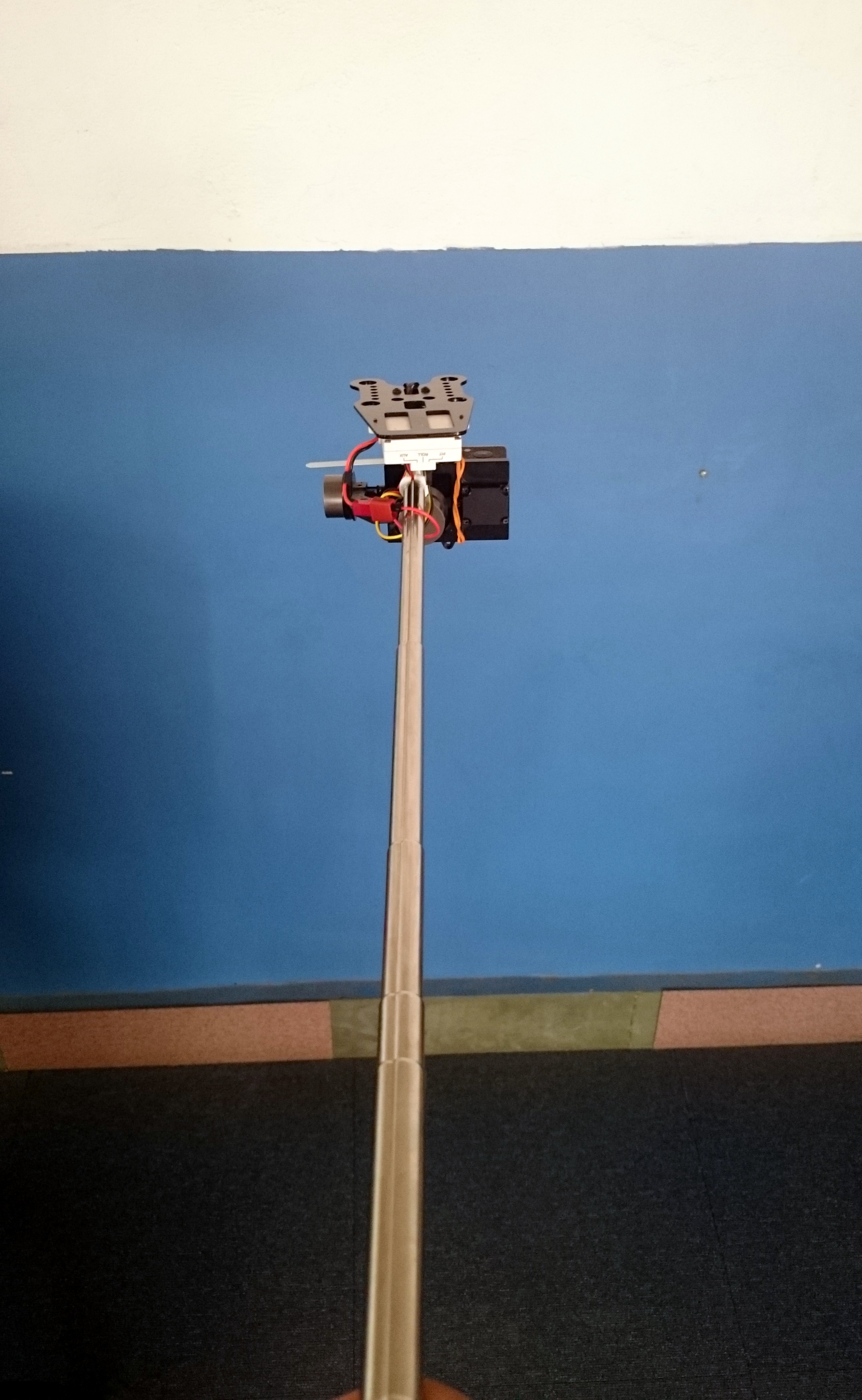
This tutorial will guide you how to hack a selfie stick and a 2D Gimbal to make an extendable handheld gimbal which can mount cameras like
- GoPro
- SJ4000/5000/6000
- Xiaomi Yi
- Walkera iLook.
A Gimbal is a stabilization mechanism which removes the shakiness of the camera upon movement and helps in giving a smooth image or video. With this build you will be able to control the tilt of the camera in the vertical direction using the buttons provided.
If you have any questions or comments please reply in comments or mail to rautmithil[at]gmail[dot]com. You can also get in touch with me @mithilraut on twitter.
To know more about me: www.mithilraut.com
Sponser: www.radlab.sfitengg.org
List of Components
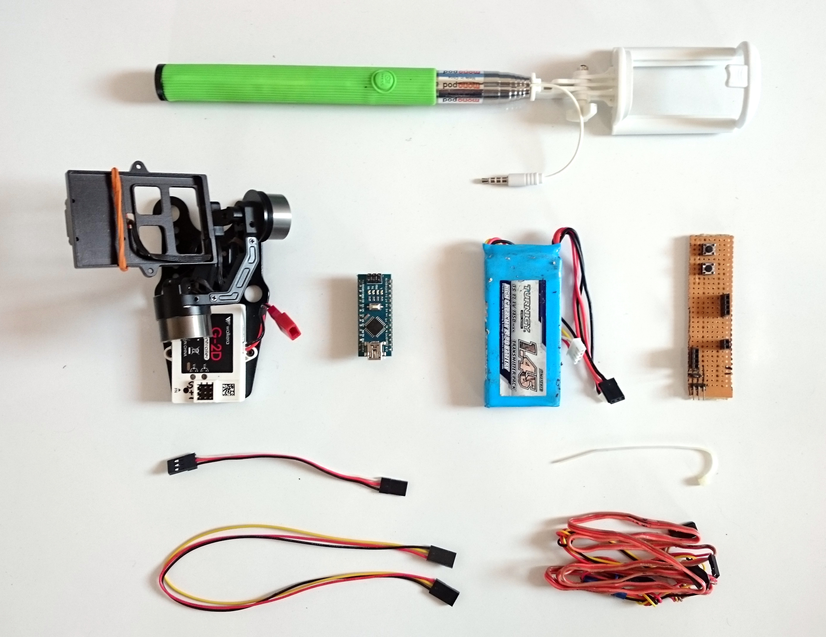
Components
- Extendable selfie stick (90cm extension).
- 2D camera Gimbal. I am using Walkera G-2D Camera Gimbal. But you can use a different one like this. Choose a lighter Gimbal for more comfort.
- Arduino Nano
- USB Type A Mini cable
- Rechargeable battery (7-12V). I am using this LiPo battery by turnigy. Make sure the size and weight is as small as possible. Smaller size will make it more handy. Also the output plug should be JST-SH type, else you will have to convert.
- Perforated prototyping board 8.5*2.5 cm.
- Tactile push button * 2 (To control the angle of tilt)
- Female burg strip (3-4cm)
- Servo extension cable
- 1 - 15cm
- 1 - 32cm
- 3 pin rainbow cable or servo cable (85cm). Check the extension of the selfie stick and get accordingly.
Tools required
- Soldering Iron and solder wire
- Double sided adhesive tape
- Insulation tape
- Cable tie 6inch * 5
Disassembling the Selfie Stick
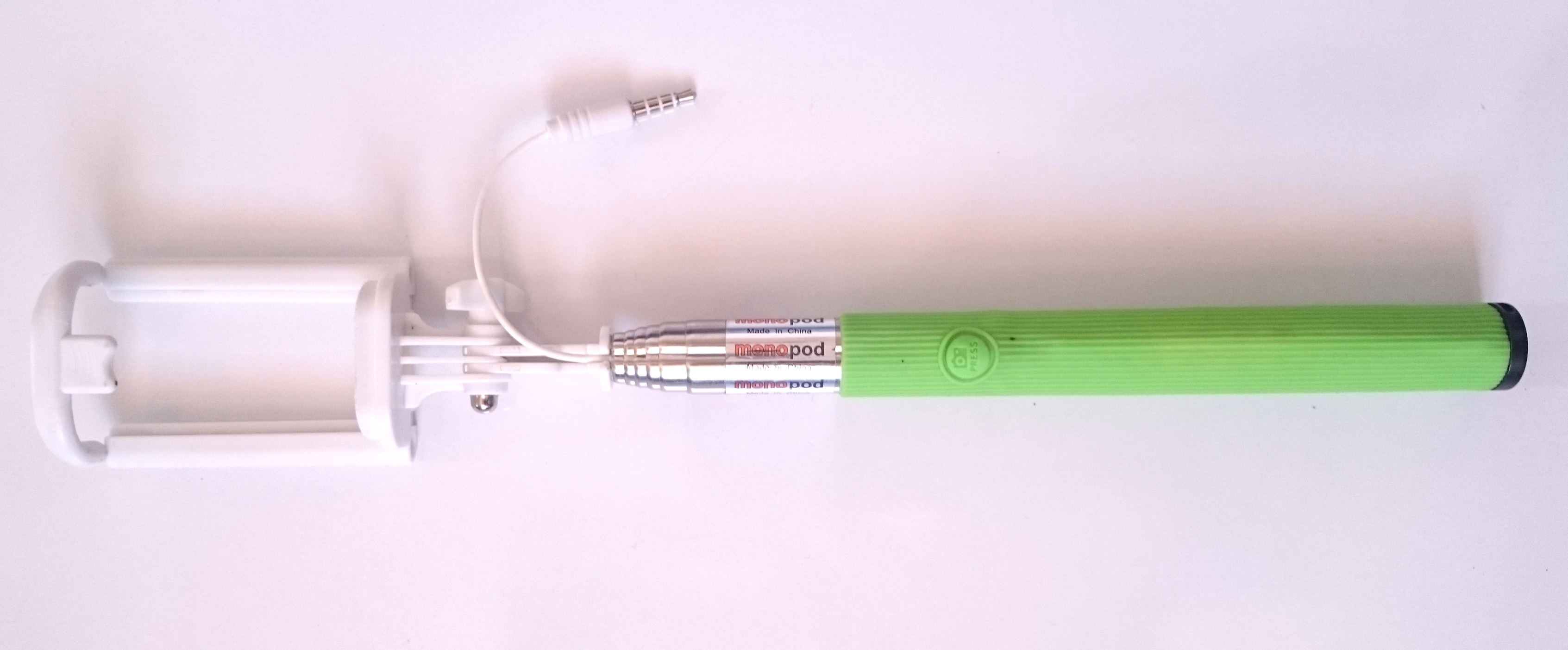
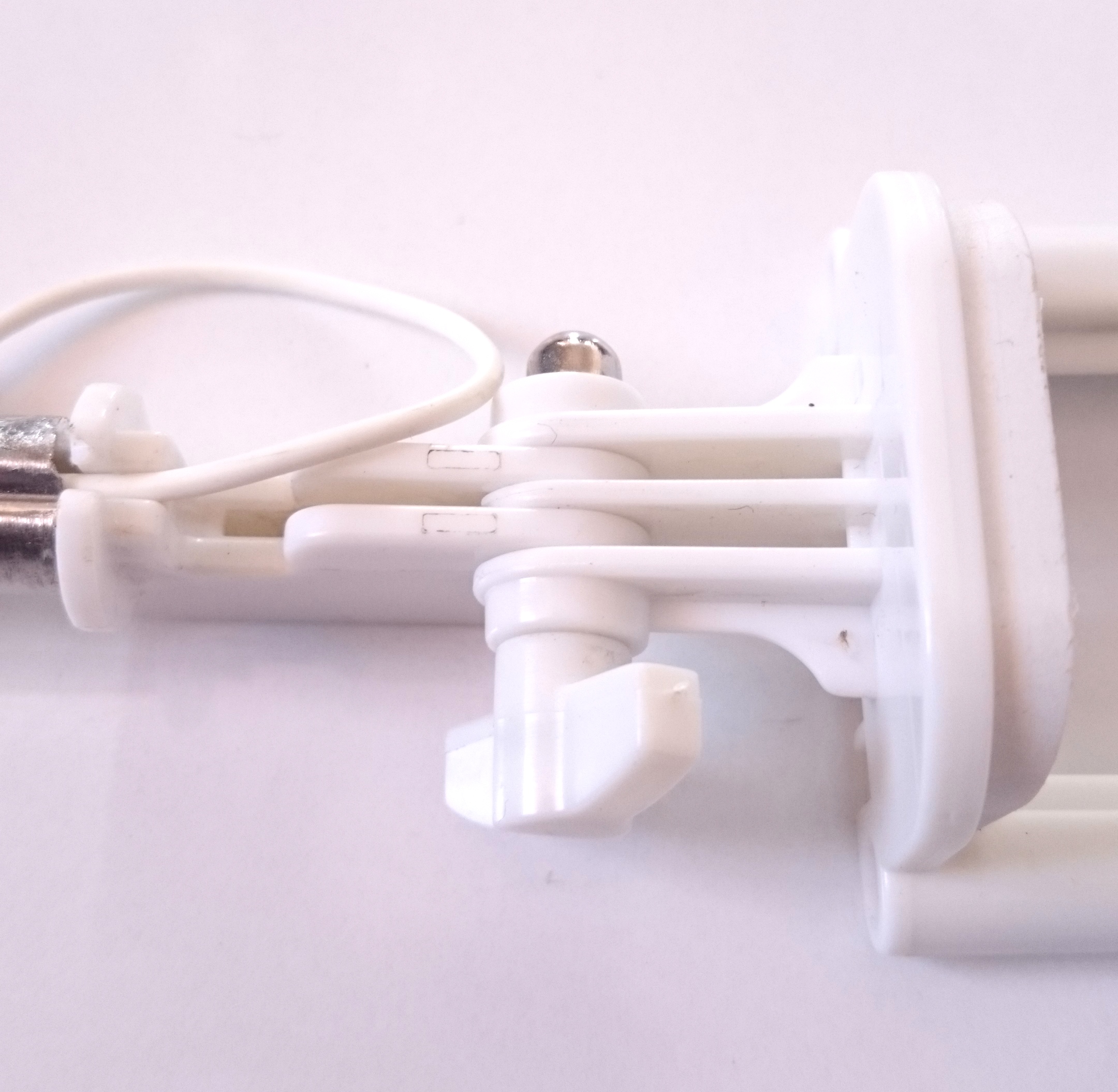
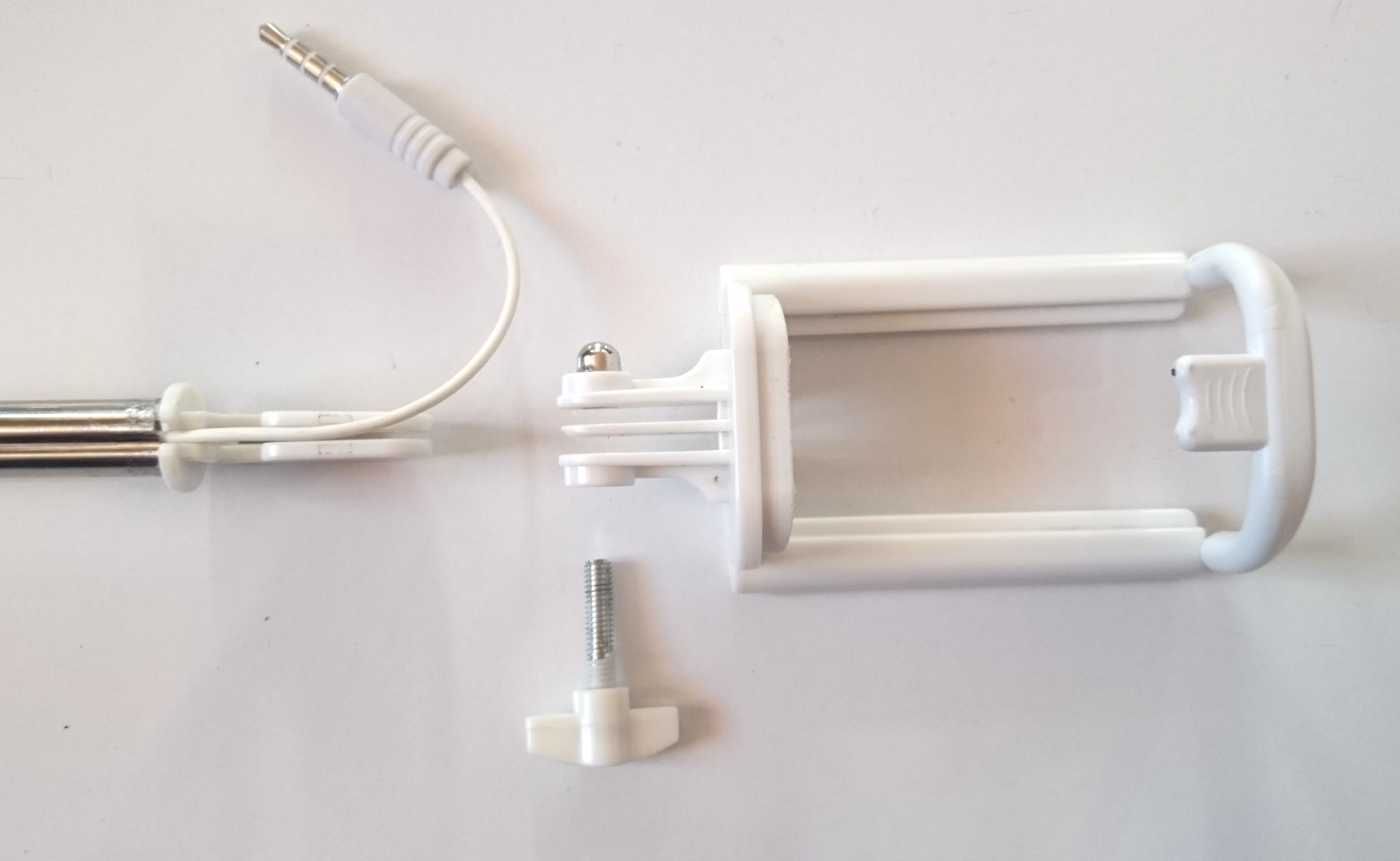
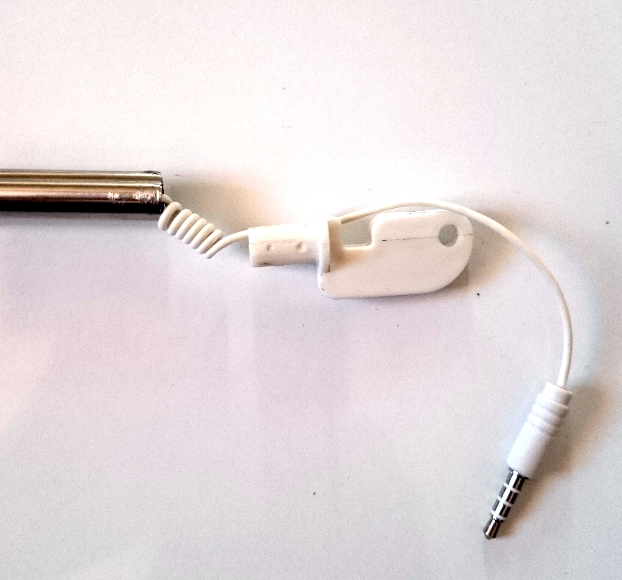
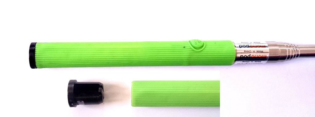

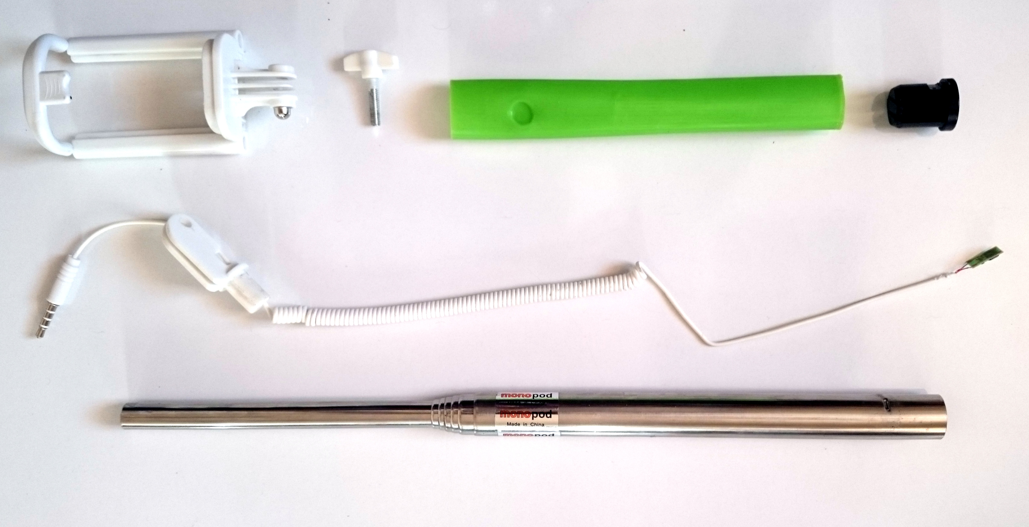
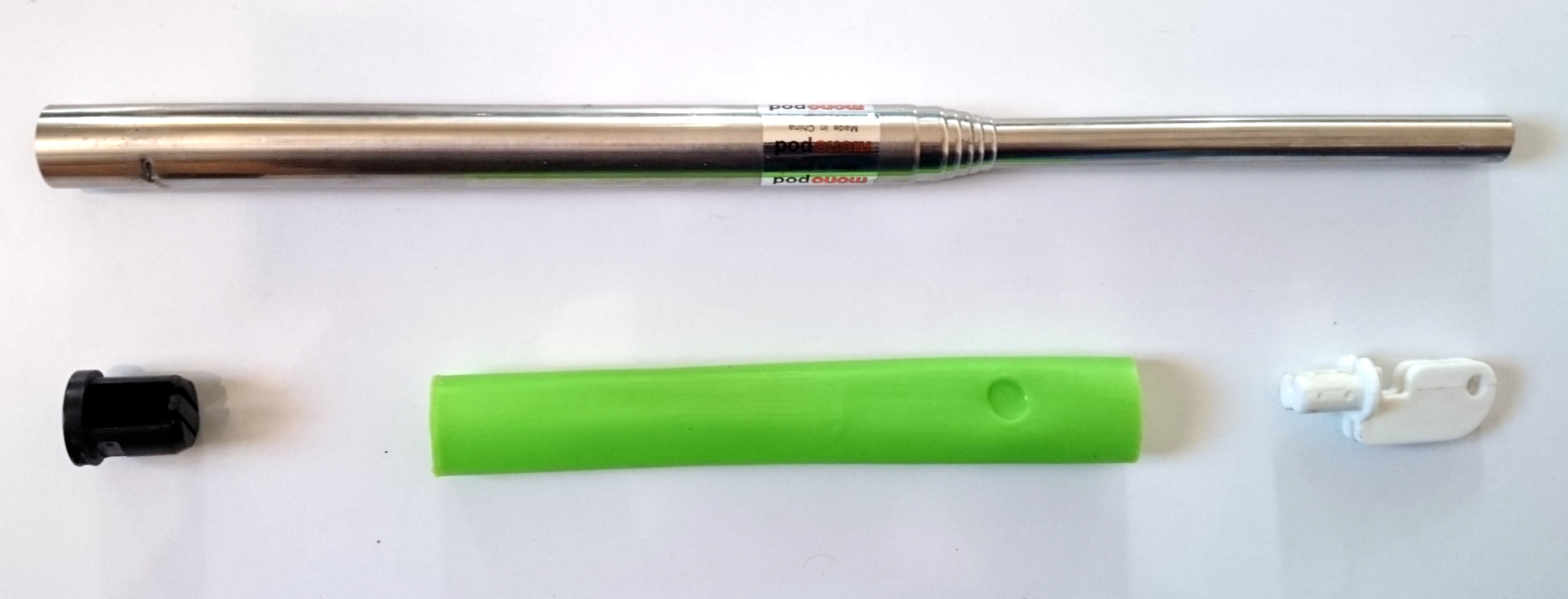
- The selfie stick consists of 3 parts. The mobile holder, the telescopic extension, the audio cable.
- Unscrew the joint between the mobile holder and stick to separate the two.
- Pull out the base of the joint from the stick using pliers. This reveals the spring audio passing through the stick.
- On the base of the stick, pull out the black cap which enclosed the audio cable.
- Pull or slide out the grip cover. This will reveal the camera trigger button. The pull the audio cable out of the stick.
- Of all the parts we require
- Extendable stick
- Base cap
- Grip cover
- Mobile holder base
Soldering the Components on the Prototyping Board
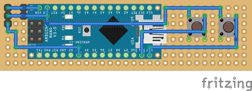
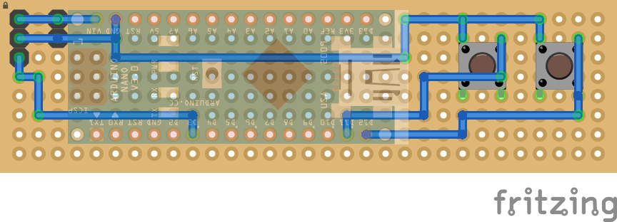
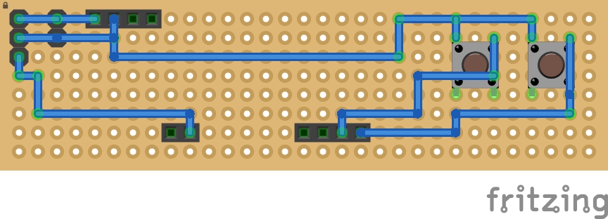
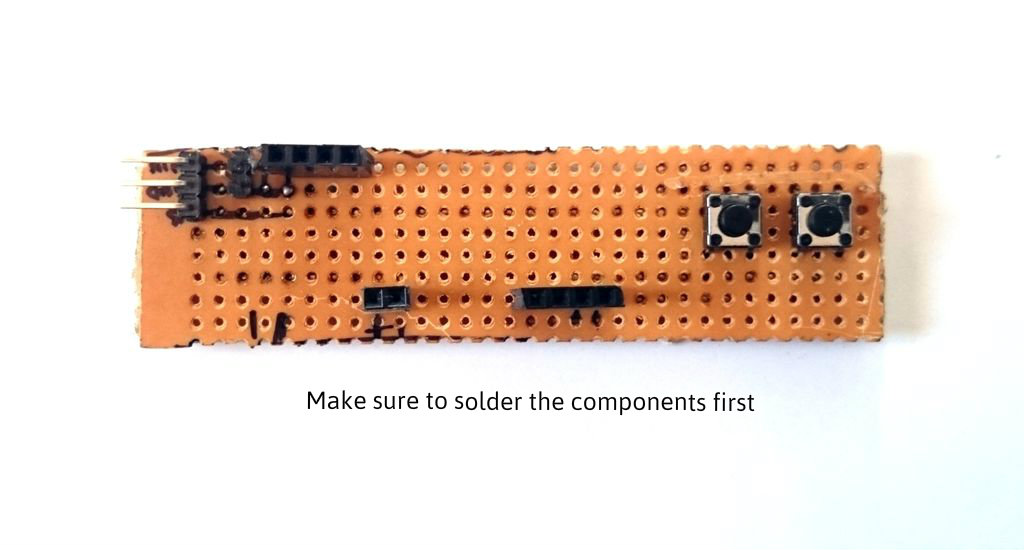

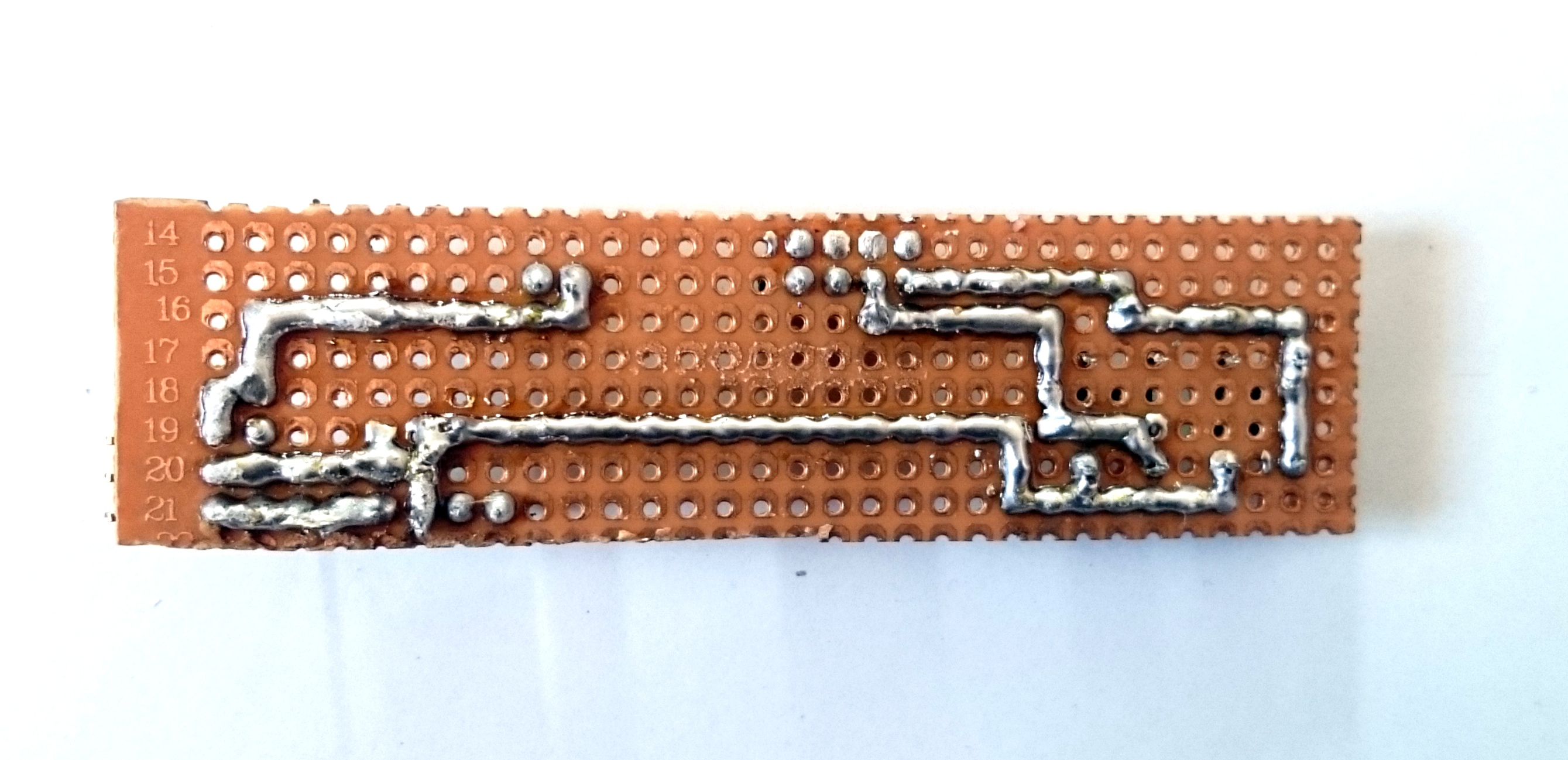
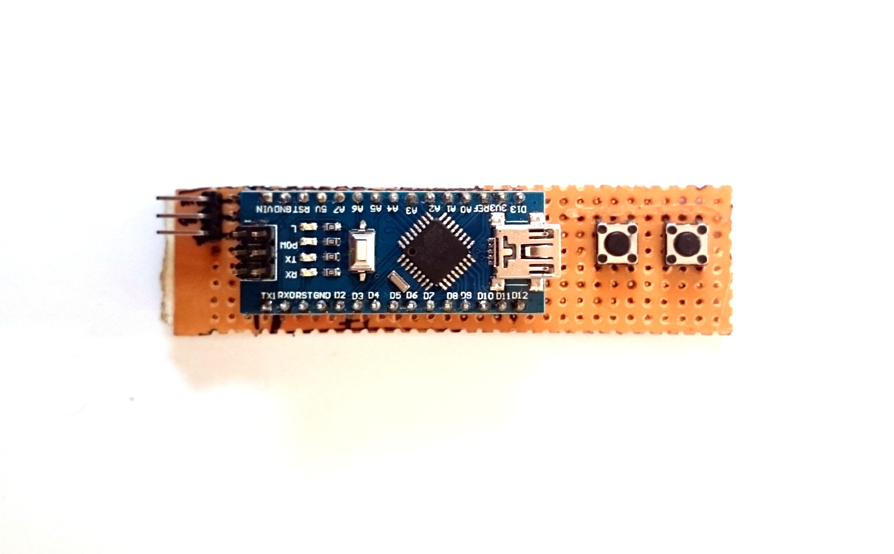
Using a marker mark the wires on the bottom side of prototyping board as shown in the image. Then solder each component. Further proceed to solder the connections on the bottom side. Once all this is done, the Arduino Nano should fit in the female berg strips as shown in the image.
Prepping the Connection Cable
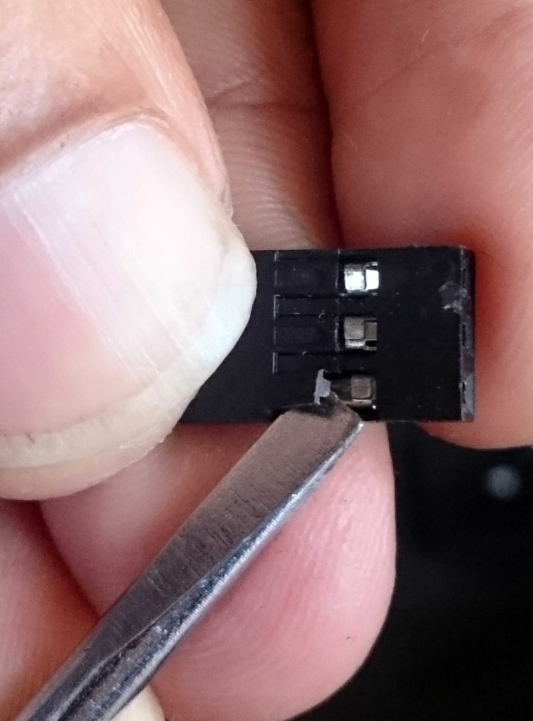
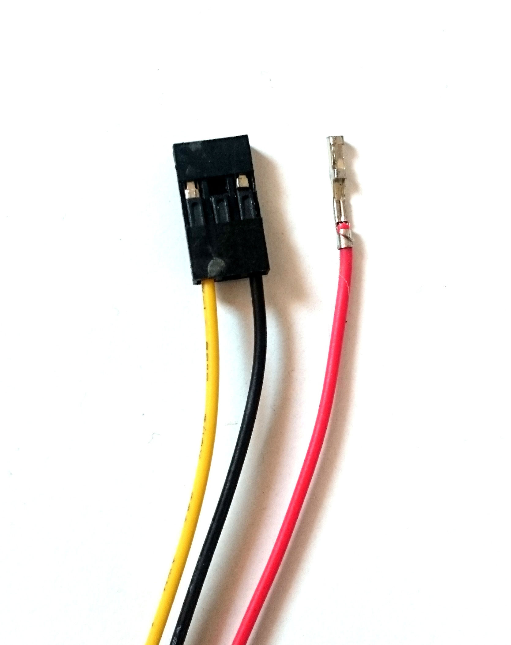
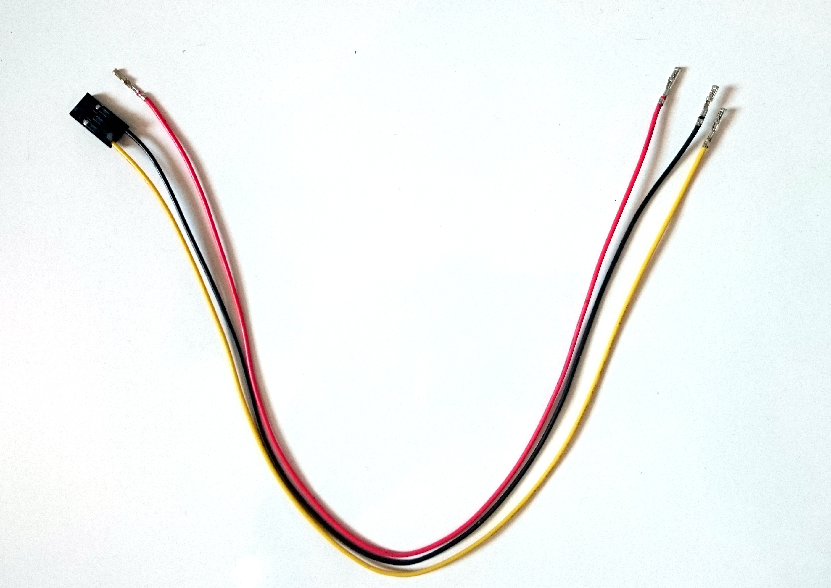

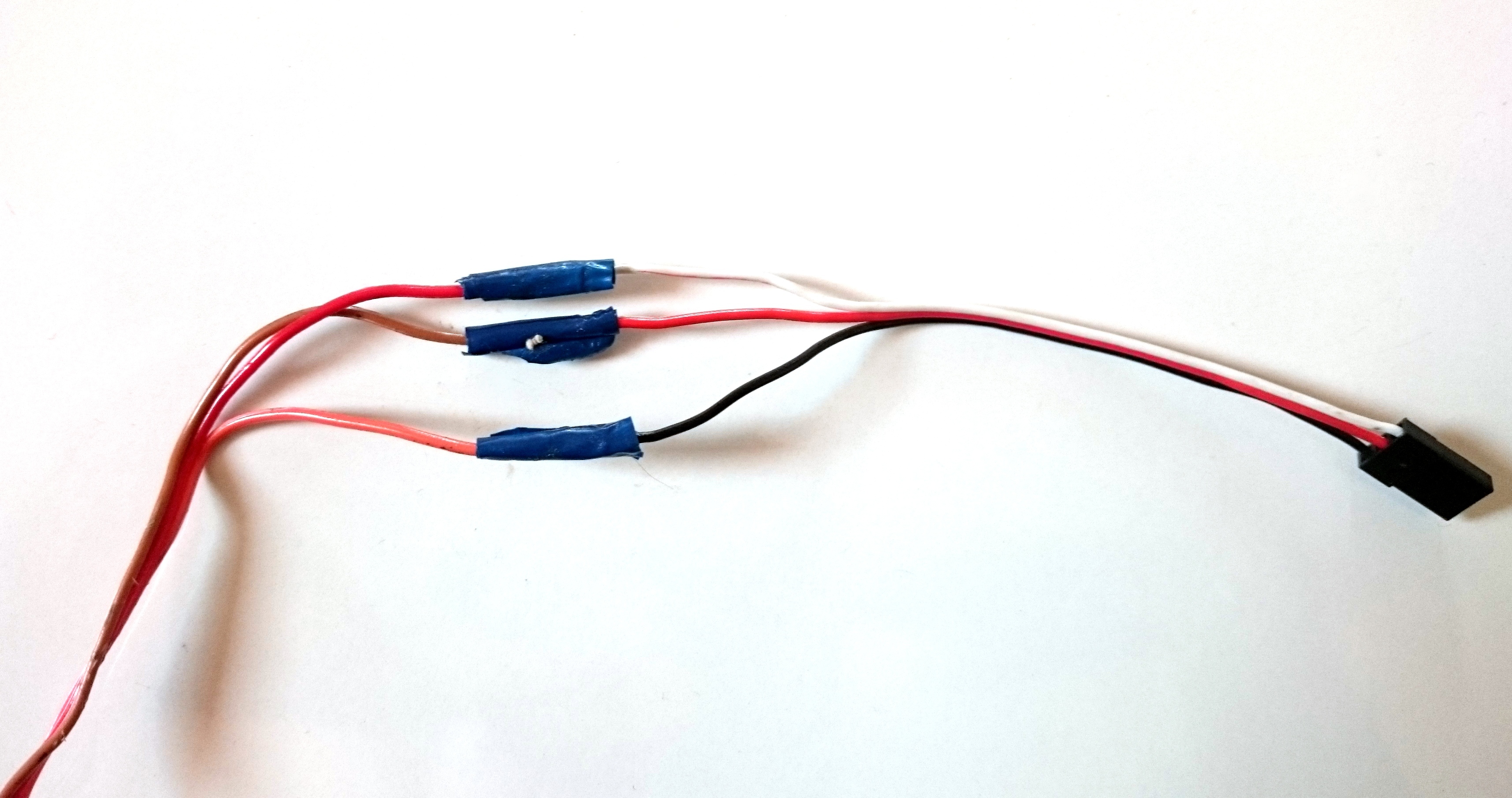
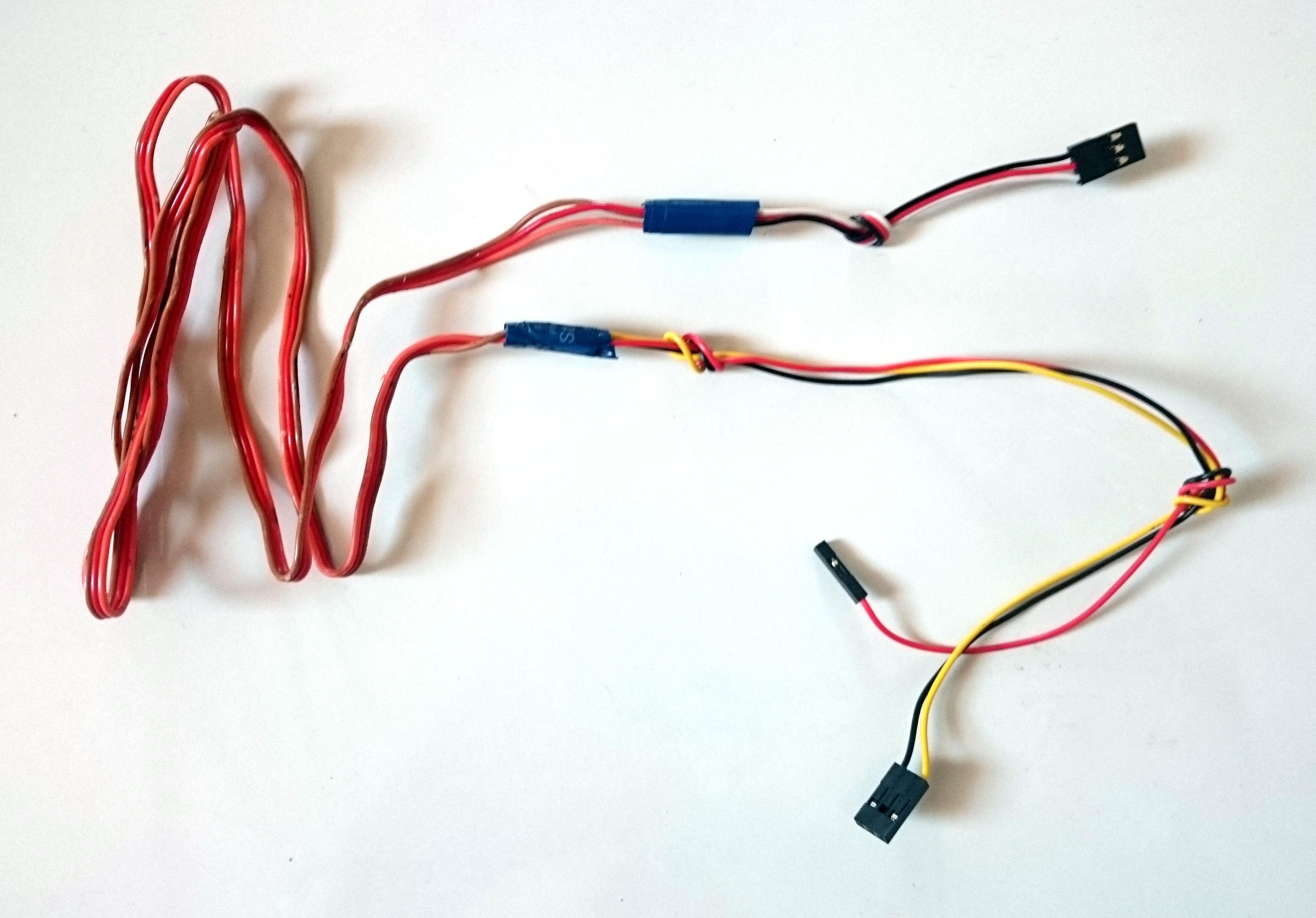
The spring audio cable only had 2 wires running through it. For operating the Gimbal, we require 3 connections i.e. Vcc, GND and Signal. So we are using a long (85cm) 3pin rainbow cable (a.k.a servo cable). Try to find a cable as thin as possible so that it fits inside the extendable stick.
For the rainbow cable:
- Using a wire stripper, strip 1cm portions of both the ends of the rainbow cable.
For 32 cm servo extension cable:
- Using a screw driver remove the red wire from the JST-SH connector from the other end and rearrange the black and yellow cables to go in the 1st and 3rd slot of the connector.
-
Strip the other end of the cable.
- Make the following connection by splicing the two ends of the rainbow cable and the servo extension cable
-
Red --- Red (Vin)
-
Orange --- Yellow (Signal)
-
Brown --- Black (GND)
(If you have a cable of other color make connections respectively)
-
- Seal each splice with insulation tape. Seal once again the group of splices with insulation tape.
Similarly for the 15 cm servo cable:
- Strip one end of the cable.
- Make the following connection by splicing the two ends of the rainbow cable and the 15 cm servo extension cable
- Red --- White (Vin)
- Brown --- Red (GND)
- Orange --- Black (Signal)
- Seal each splice with insulation tape. Seal once again the group of splices with insulation tape.
Note: It is important to maintain polarity on both sides which is why rearranging the cables within the connector is required.
Reassembling the Stick
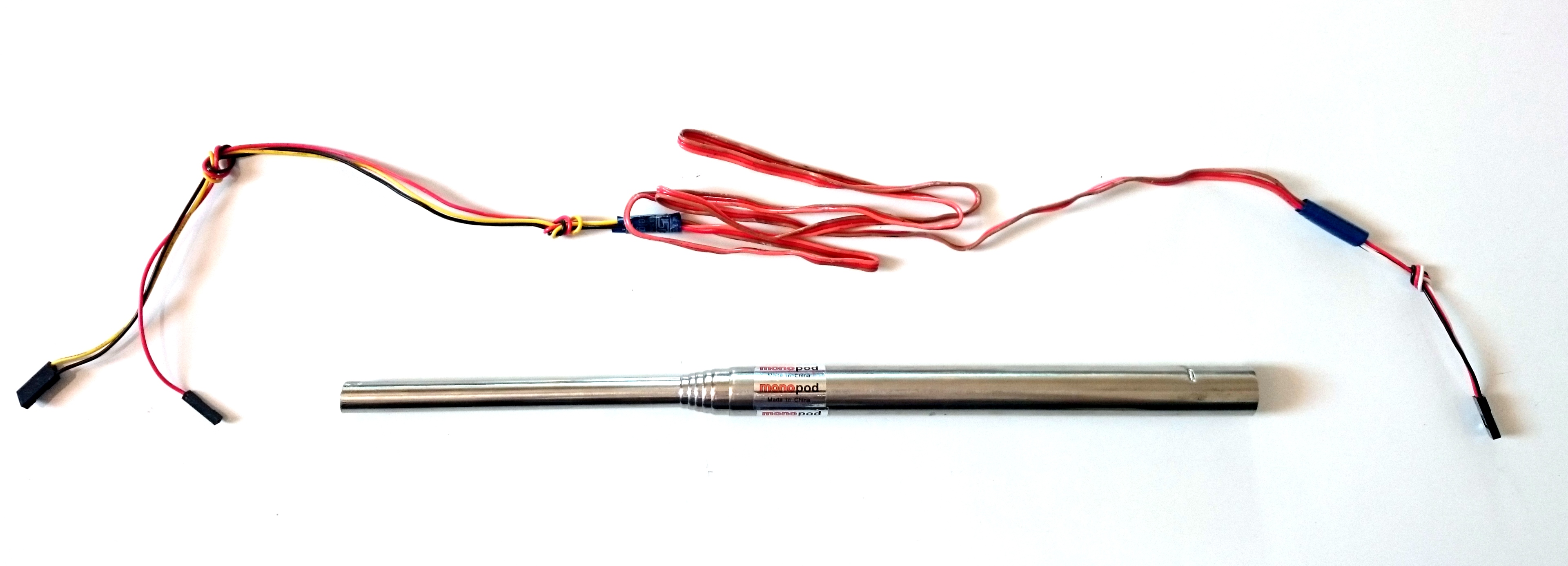


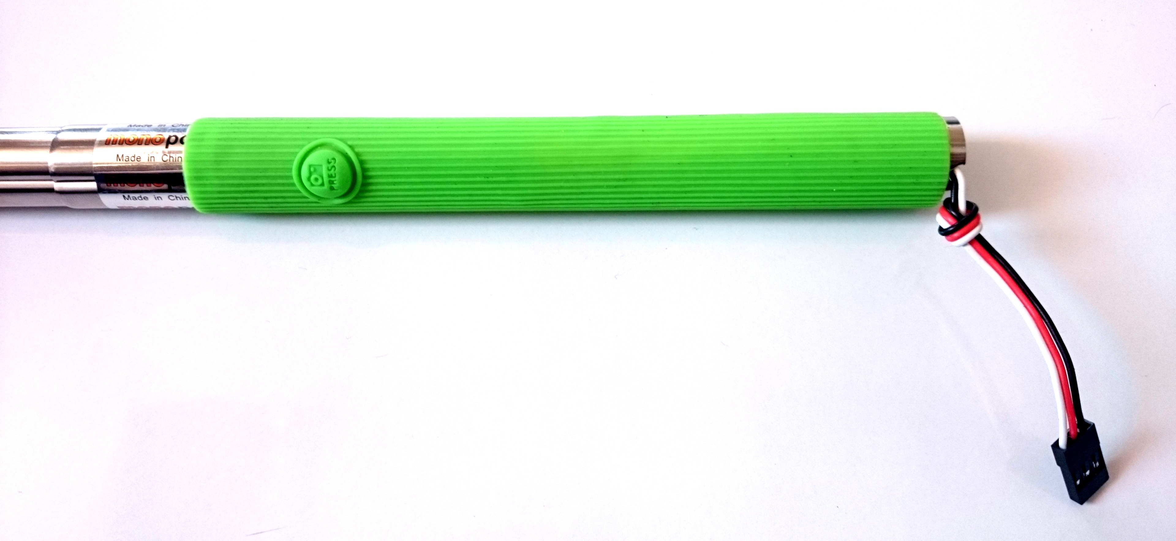
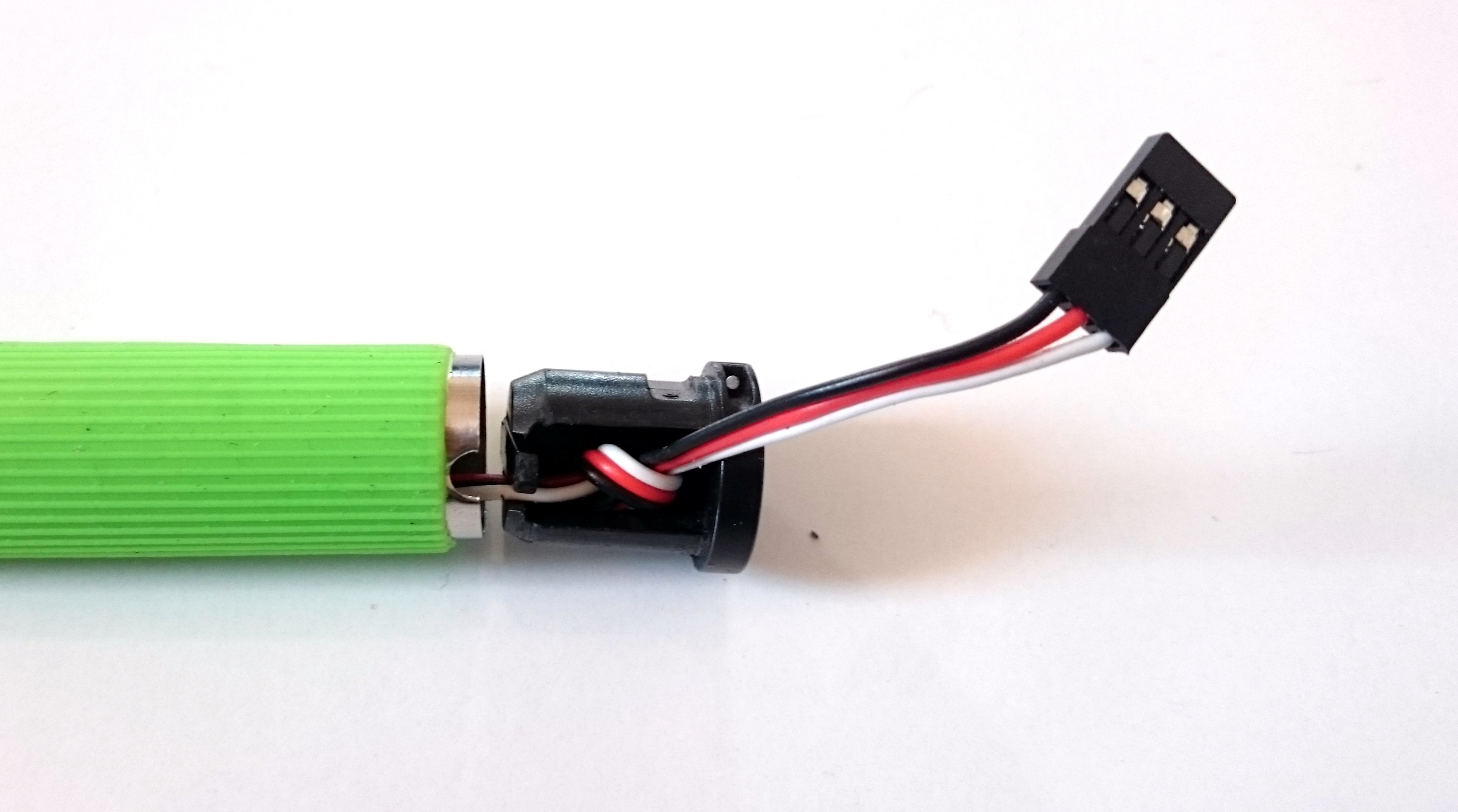
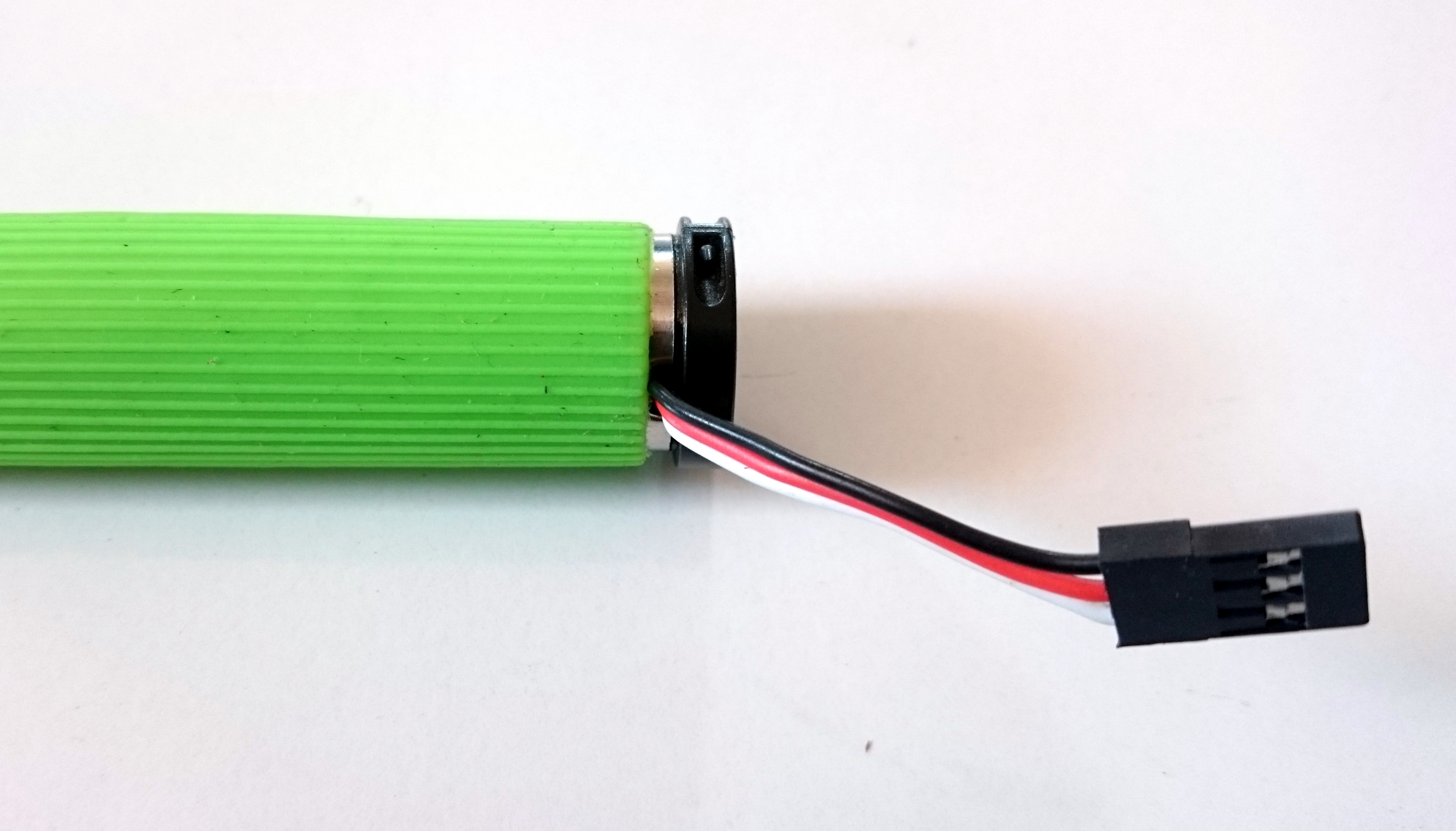
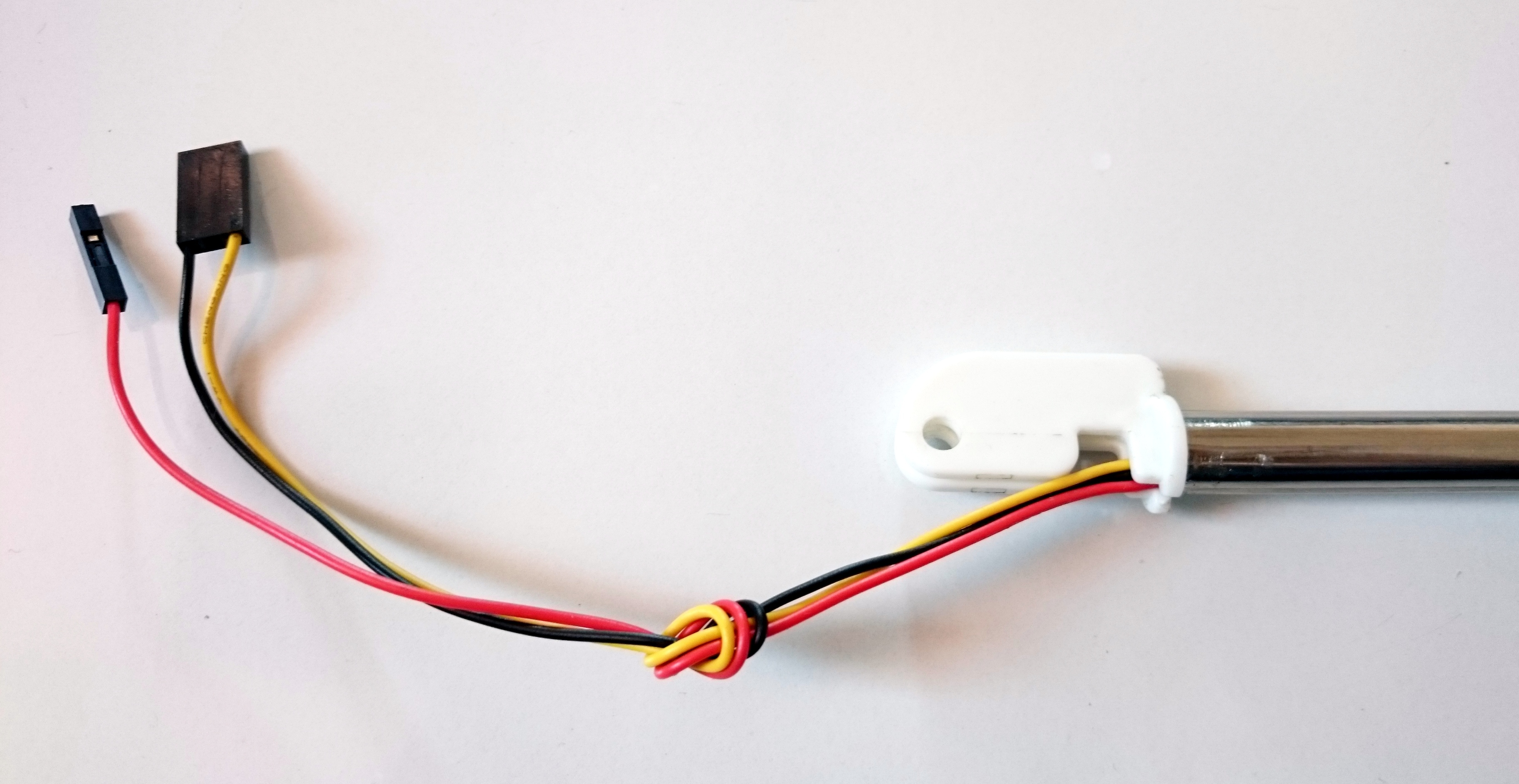
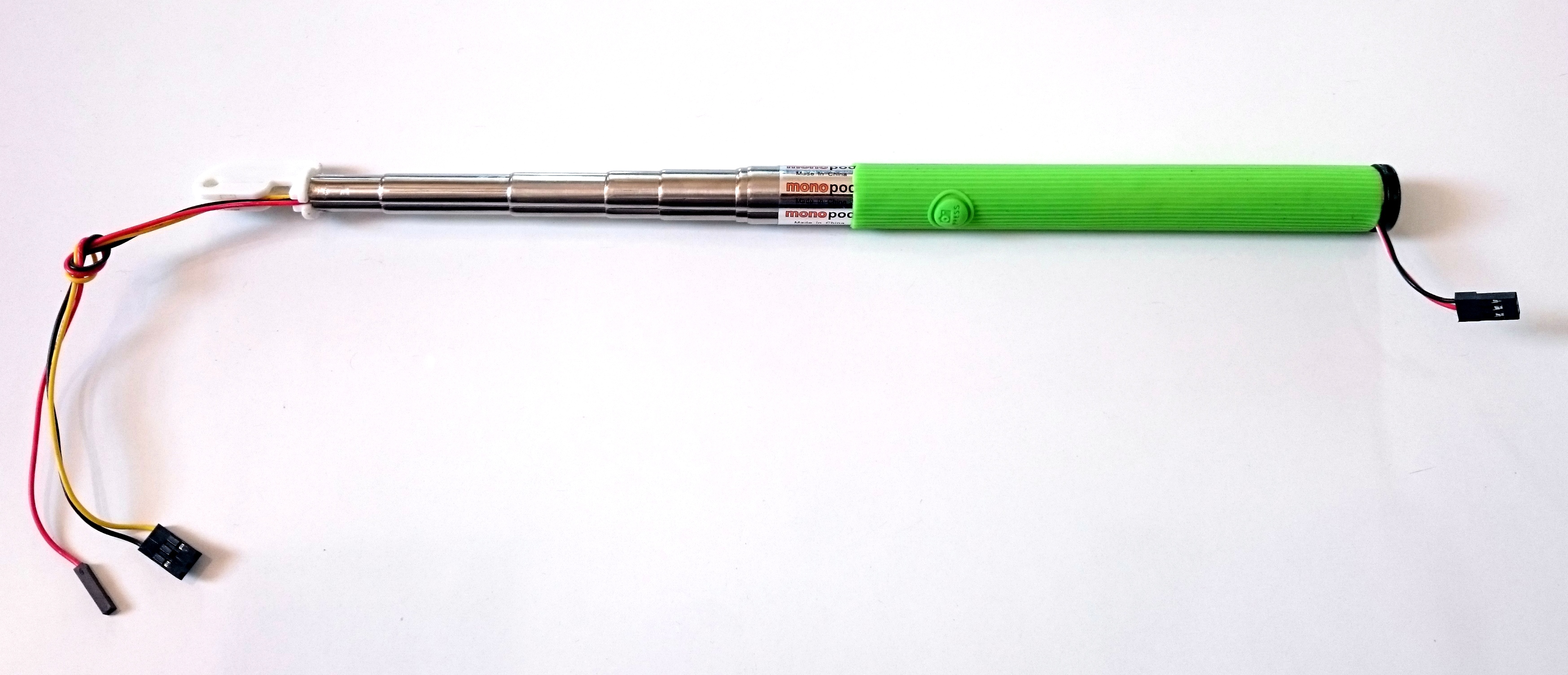
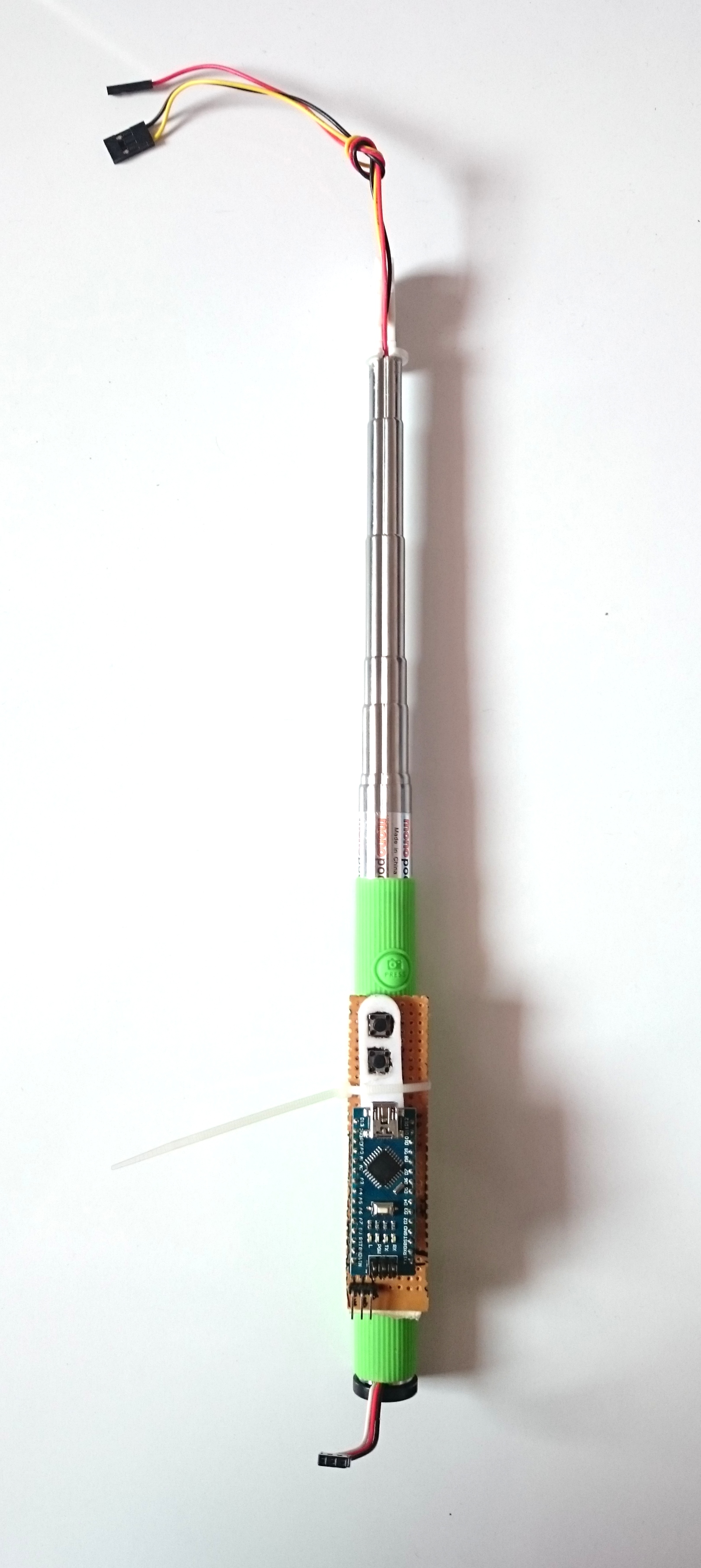
Take the connection cable prepped in step4 and insert in into the telescopic stick. The 15 cm servo cable end will be on the bottom side and the 32 cm servo cable end will come out on the top as shown in the image. Now extend the stick to its maximum length and ensure that both the servo cable stay outside. Put the grip back into its place.
On the bottom side of the stick make a knot in the 15cm servo cable leaving about 5-7cm outside the knot. Insert this knot into the bottom cap and insert the cap back into its position in the stick. There is a notch in the stick which allows the wire to come out without getting damaged.
On the top side, insert the '32 cm servo cable' through the 'mobile holder base' and fix the base inside the stick as shown in the image.
Now contract the stick slowly until the point where it cannot contract further. You may notice that the stick doesn't contract to its full capacity because of the bulk of the wire placed inside the stick.
Programming the Arduino Nano
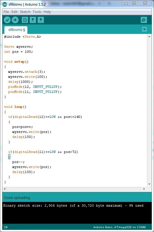
The two tactile push button on the PCB are to adjust the tilt of the camera on the go. Connect the Arduino Nano to a computer using a USB Type A Mini cable. If you don't have Arduino IDE installed then follow the instruction given here. Wait for the Arduino Nano drivers to be installed. Start the Arduino IDE and write the follwoing program.
#include <Servo.h>

Servo myservo;
int pos = 100;

void setup()
{
  myservo.attach(3);
  myservo.write(100);
  delay(1000);
  pinMode(12, INPUT_PULLUP);
  pinMode(11, INPUT_PULLUP);
}


void loop()
{
  if(digitalRead(12)==LOW && pos<=140)
  {
    pos++;
    myservo.write(pos);
    delay(150);
  }
  if(digitalRead(11)==LOW && pos>72)
  {
    pos--;
    myservo.write(pos);
    delay(150);
  }
}
Attaching the Circuit and Battery to the Stick
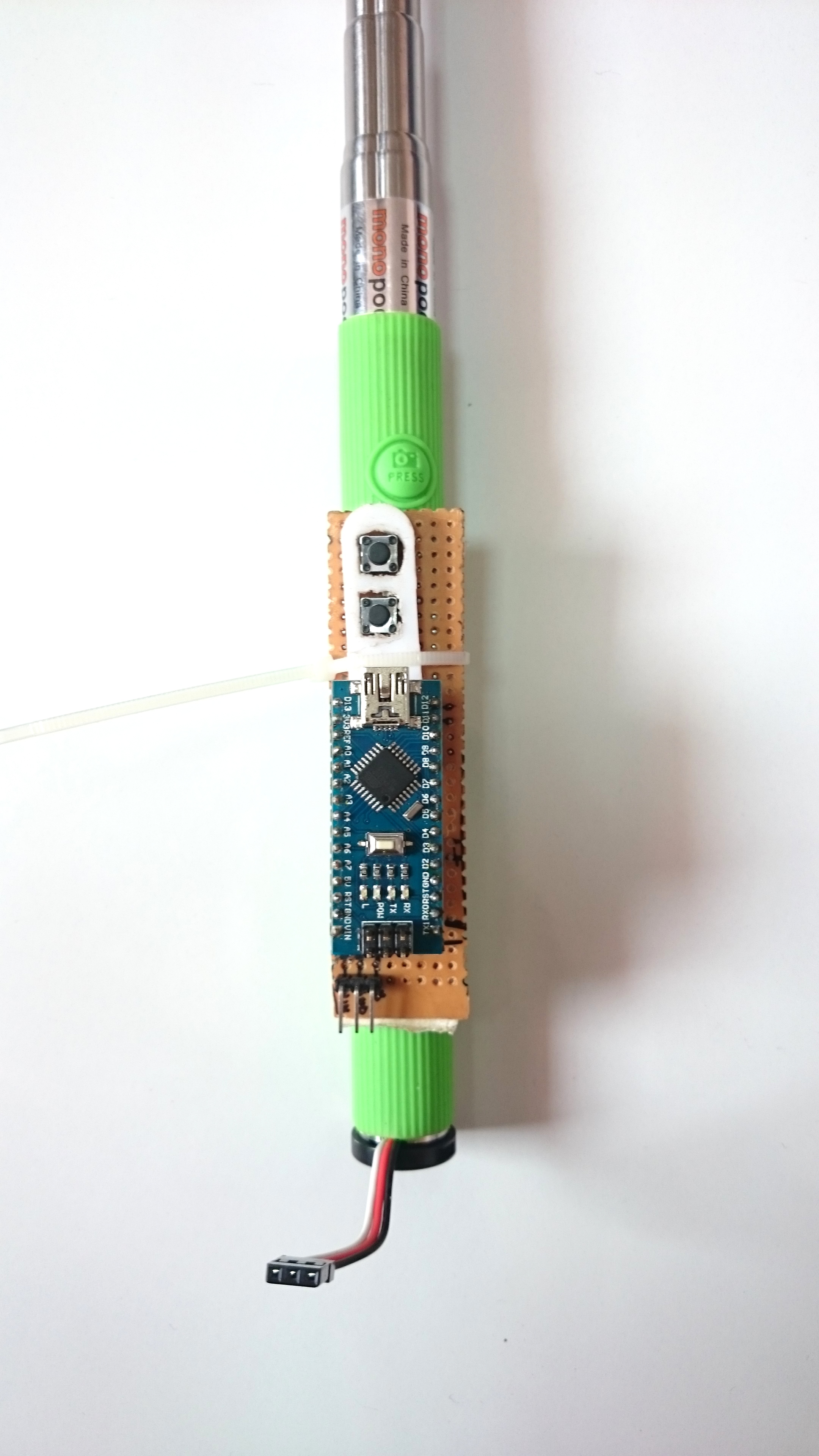
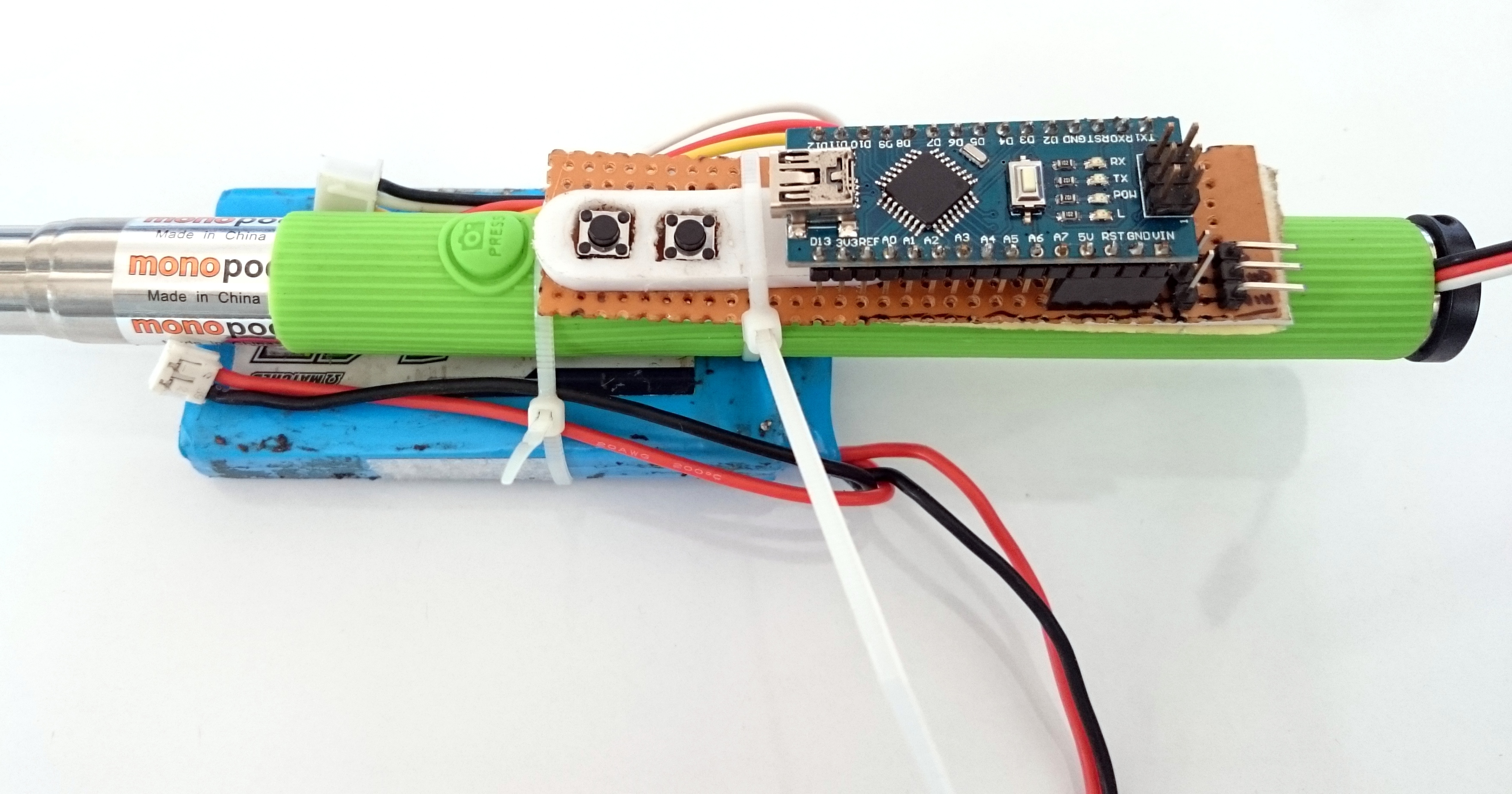
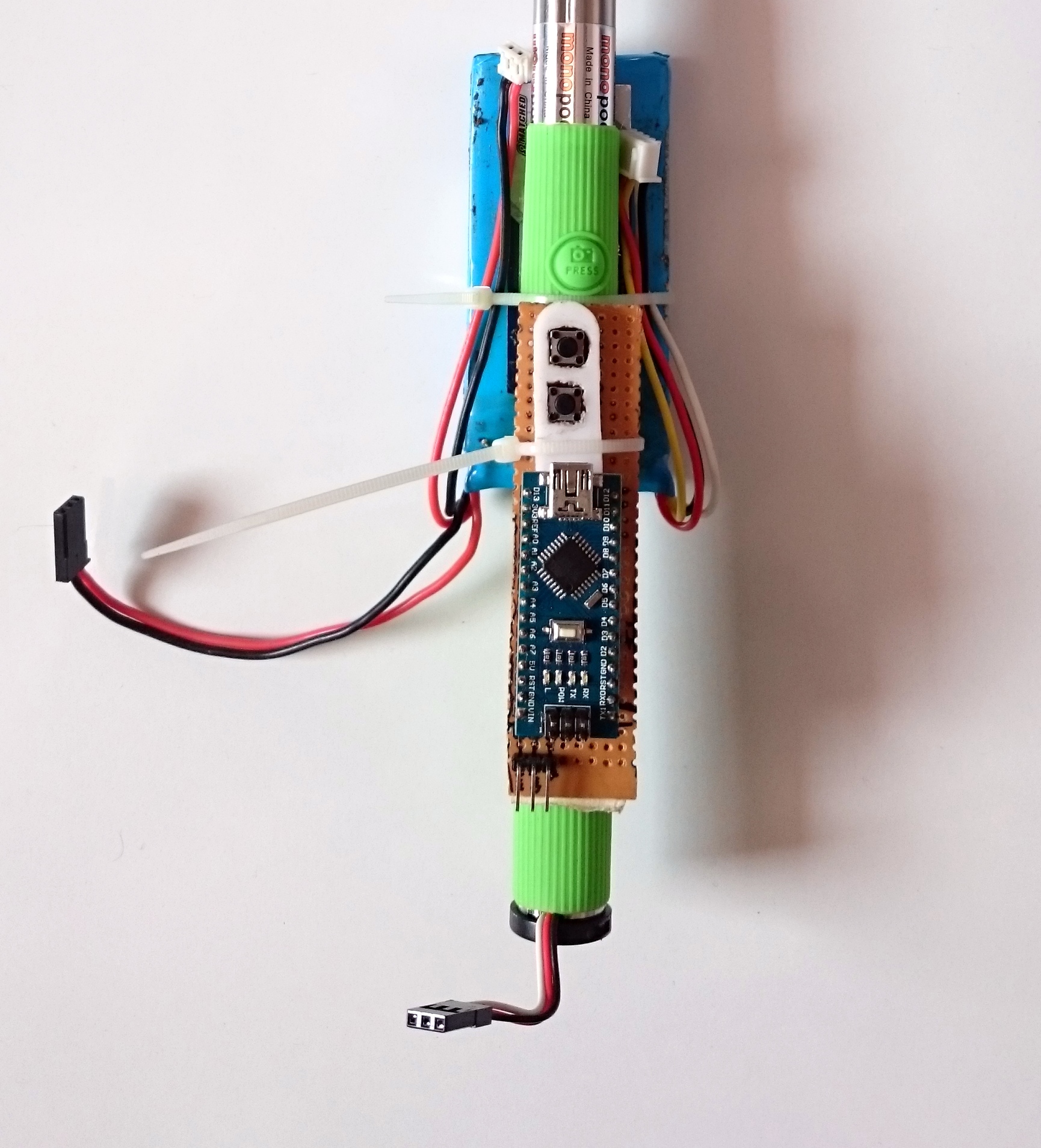
Place the stick straight with the trigger button pointing upwards. Remove the protecting cover of the double sided tape on the bottom of the PCB and stick the PCB on the grip cover. Secure this using a cable tie.
Next place the battery on the lower side of the stick and secure it with a cable tie. Adjust the position of the battery by holding the stick in your hand and operating the two buttons with your thumb.
Attaching the Gimbal
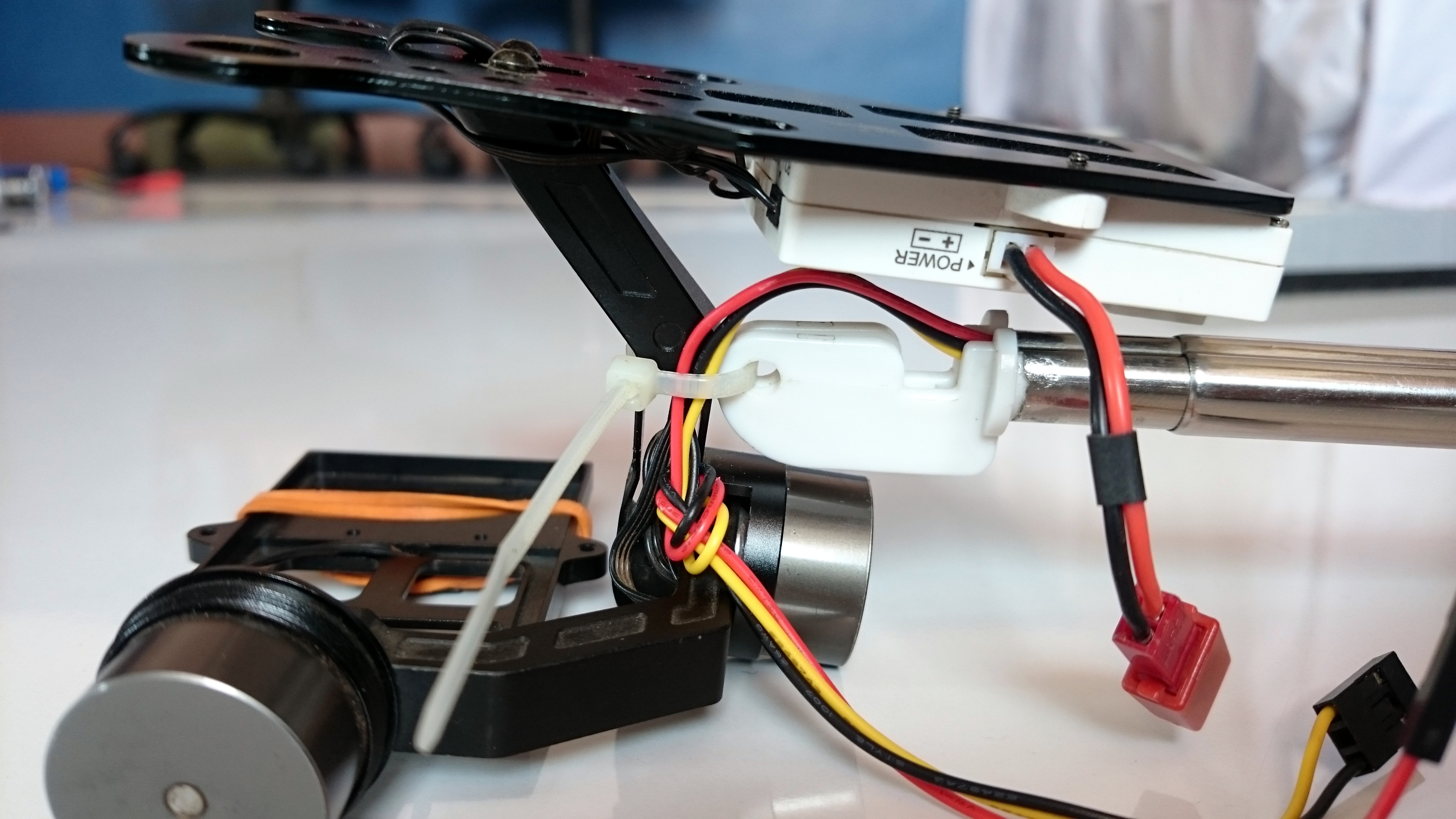
On the upper side, insert a cable tie in the 'Mobile holder base'. Place the center arm of the Gimbal in front of the base and secure it tightly with a cable tie as shown in the image. Although this looks like a weak attachment the shape of the mobile holder restricts the Gimbal from tilting down.
Making the Connections
Connections of the Gimbal
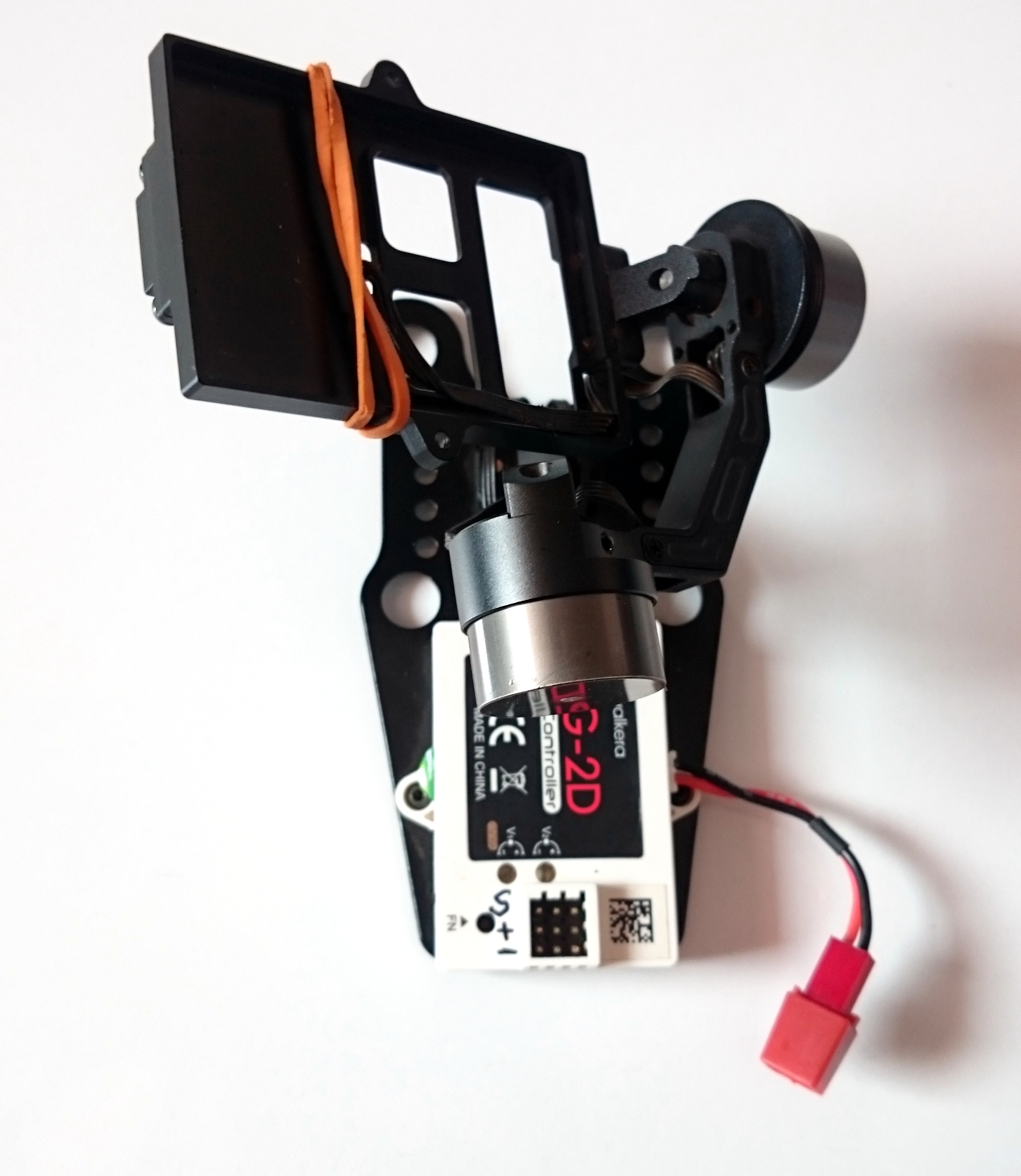
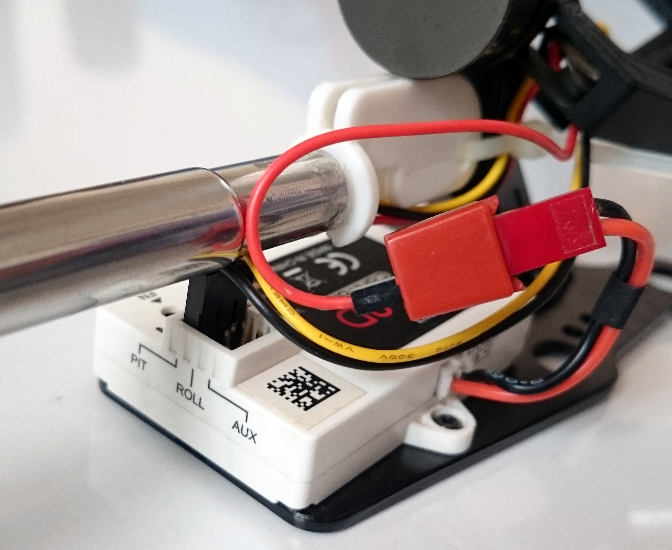
- As shown in the diagram, connect the 'Yellow' and 'Black' cable in the JST connector ti the 'Signal' and '-' terminals of the "PIT" column.
- Connect the 'Red' cable to the Red wire of the power connector.
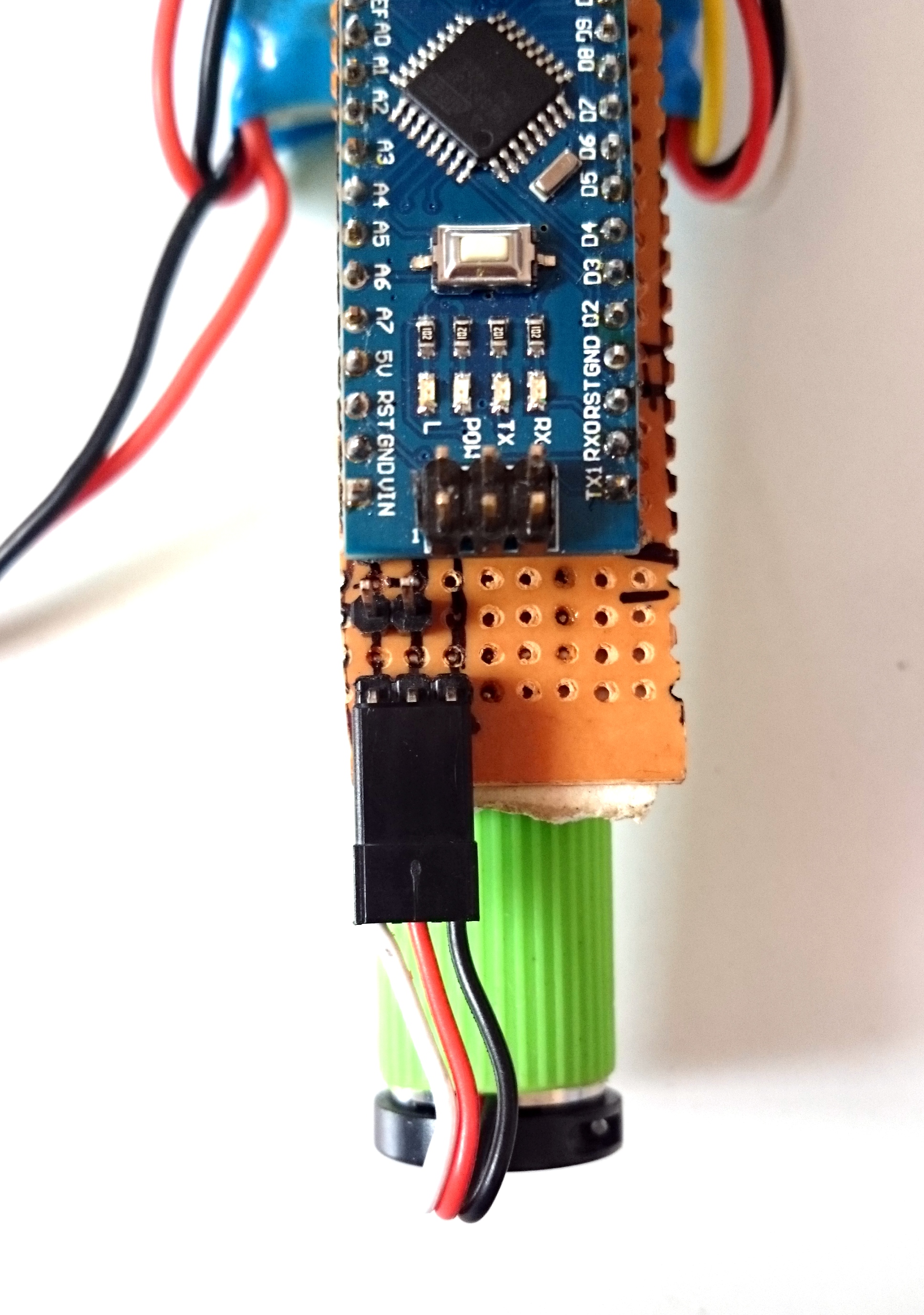
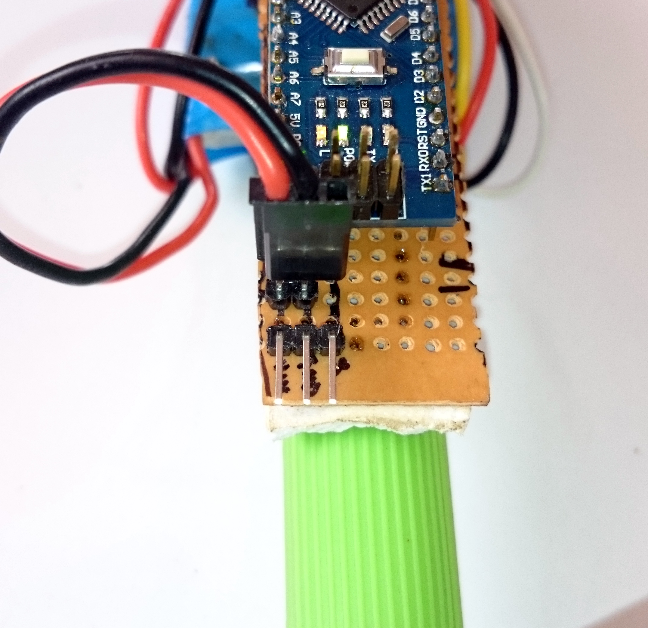
Connections of Signal cable.
- On the lower side connect the 15cm servo cable to the 3pins as shown in the diagram. From Left to Right White
Red
Black
MAINTAINING THIS ORDER IS IMPORTANT ELSE THE GIMBAL MAY GET DAMAGED.
Connecting the Battery
- Connect the Red or Positive on the Left.
- Connect the Black or Negative on the Right.
MAINTAINING THIS ORDER IS IMPORTANT ELSE THE GIMBAL AND ARDUINO MAY GET DAMAGED.