Exporting a .dxf File From Fusion 360 (for Laser, Waterjet)
by TaylorSharpe in Workshop > Laser Cutting
13459 Views, 11 Favorites, 0 Comments
Exporting a .dxf File From Fusion 360 (for Laser, Waterjet)
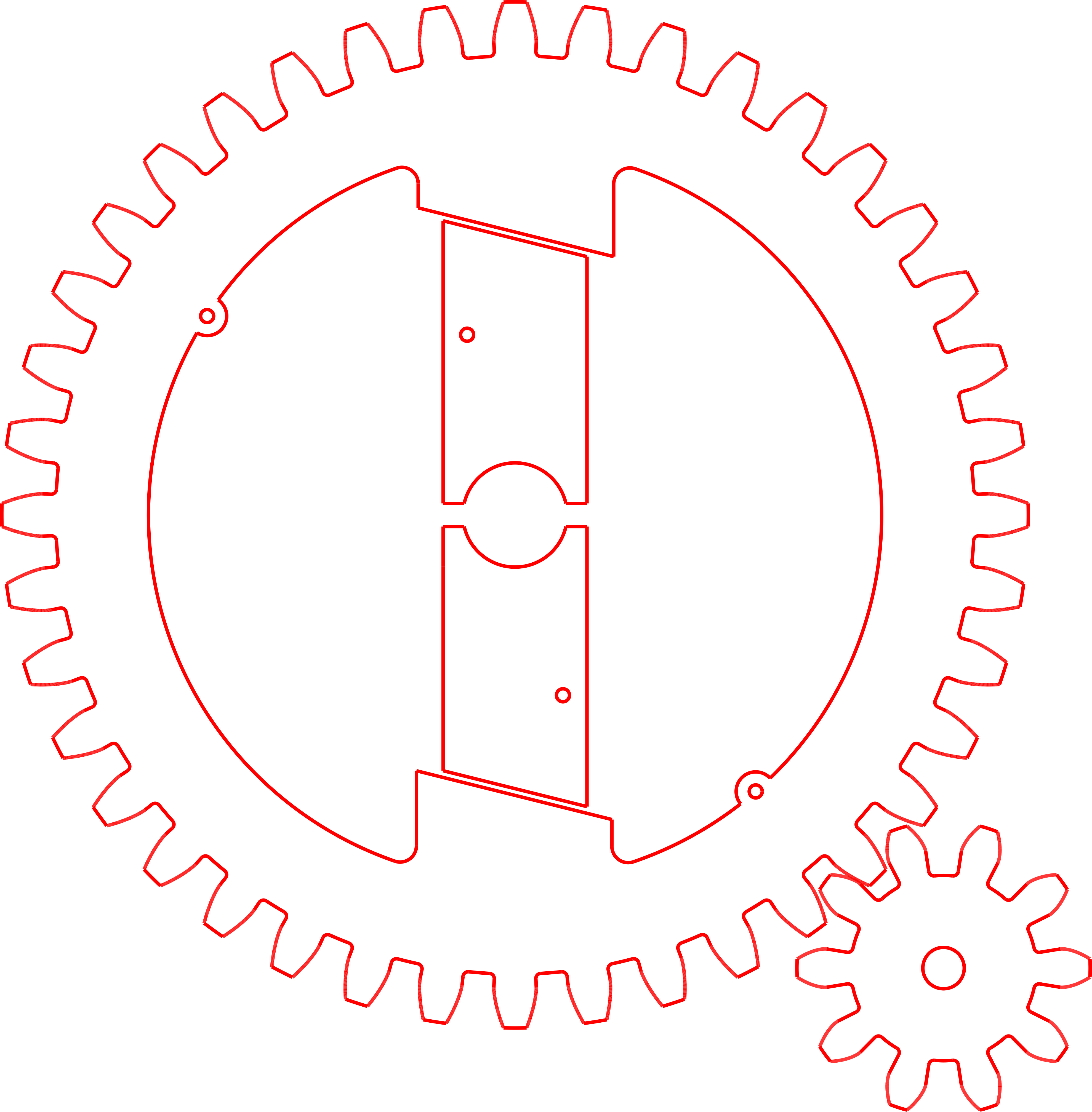
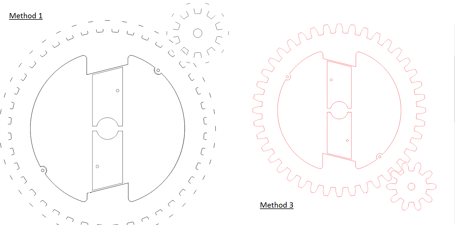
It doesn't seem like it should be too hard to export a high-quality DXF from Fusion 360 for use with laser cutters or waterjets. But depending on your part, sometimes it really can be difficult. You'll end up with files that represent some of your part's curves but not others; with curves broken up in weird ways, or with curvatures changed; or with phantom lines on top of other lines, that the laser cutter will usually cut twice.
I've found 3 main approaches for exporting a .dxf. Usually I try the easiest approach first, then move on to the other two if necessary.
Approaches covered in this Instructable:
(1) SIMPLE SKETCH METHOD: Create a sketch, project an outline, and directly save as .dxf
(2) SHEET METAL METHOD: Use the new Sheet Metal DXF Export command (even if your part isn't a sheet metal part!)
(3) POST-PROCESSOR METHOD: Use a laser CAM toolpath and a custom post-processor to generate a .dxf
The Simple Sketch Method
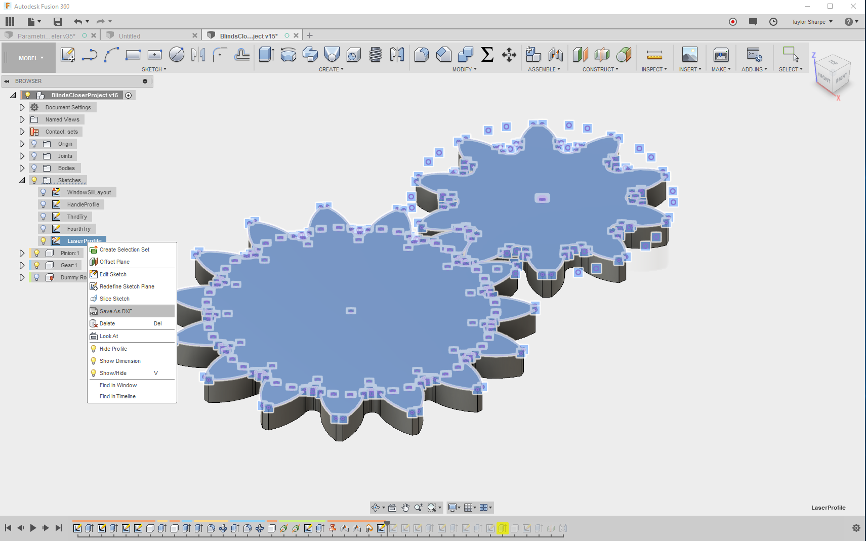
This method works for me about half of the time. Its chances of success seem to really depend on the type of geometry you're trying to convert to a .dxf. It's also the "classic" way to export part outlines to a .dxf file from Fusion 360. If you can get away with it, this method can save you a lot of time.
(1) Create a sketch and give it a name like "Laser Profile". I often like to keep my laser profile sketches in the top level of my multi-component designs.
(2) Project the outlines of any parts you want to include in your .dxf.
(3) Close the sketch, right-click on it, and choose "Save as DXF."
The Sheet Metal Method
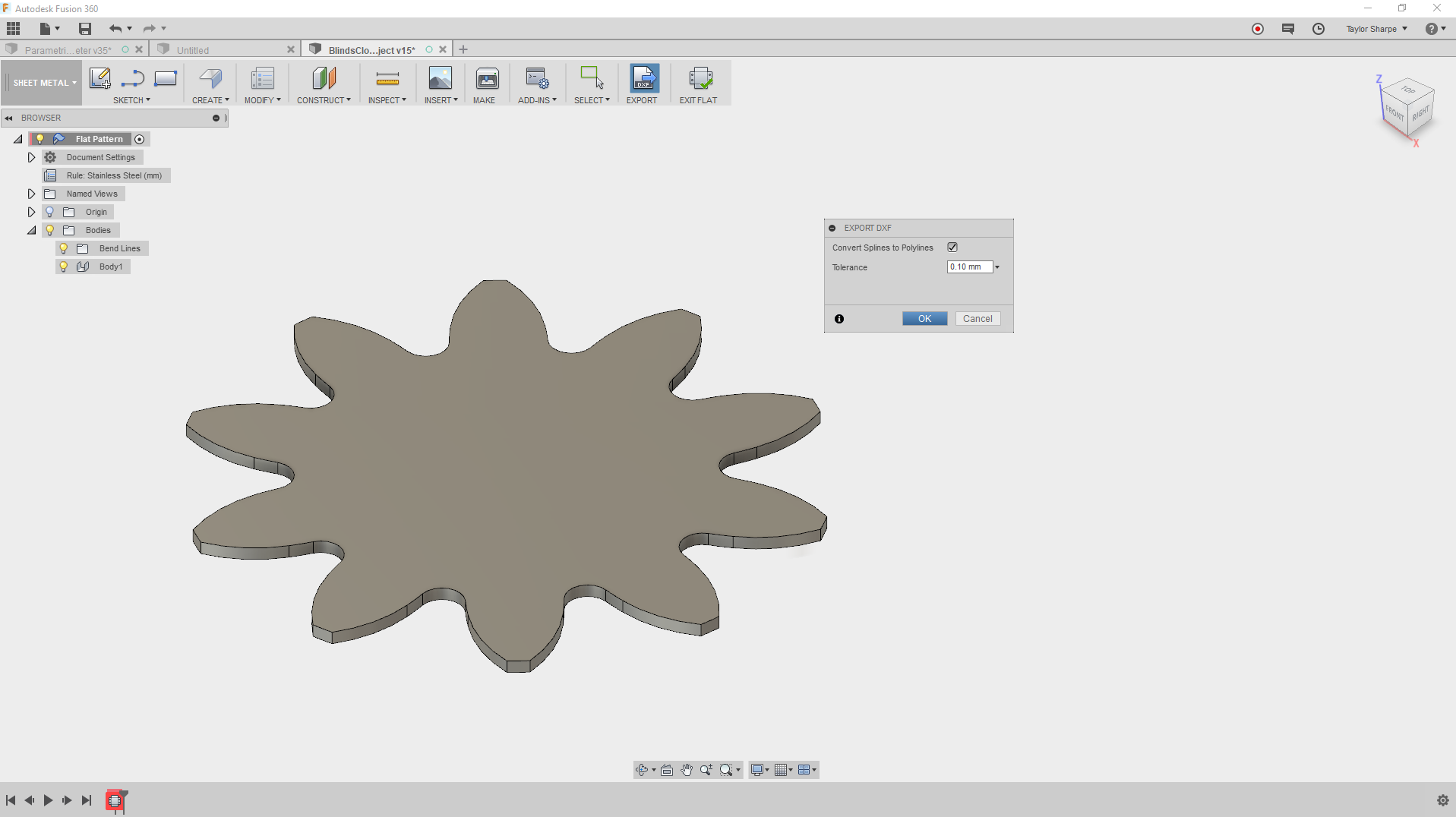
This method seems to work a little better than Method 1, but I've still seen quite a few failed file exports here.
Fusion 360's sheet metal workspace includes the ability to export .dxf files pretty easily. But for the purpose of this Instructable, we'll show how to make this workflow work for parts that aren't actually sheet metal parts.
(1) Create a plane above your part, at some set distance.
(2) Make a new sheet metal component (or two) by using a projected sketch and the sheet metal flange tool.
(3) Make a flat pattern for each of your "mirror" sheet metal parts.
(4) Export each .dxf outline from the command bar.
Note that if your first attempt doesn't work well, you can try checking "Convert Splines to Polylines". This will often improve the results.
The Post Processor Method
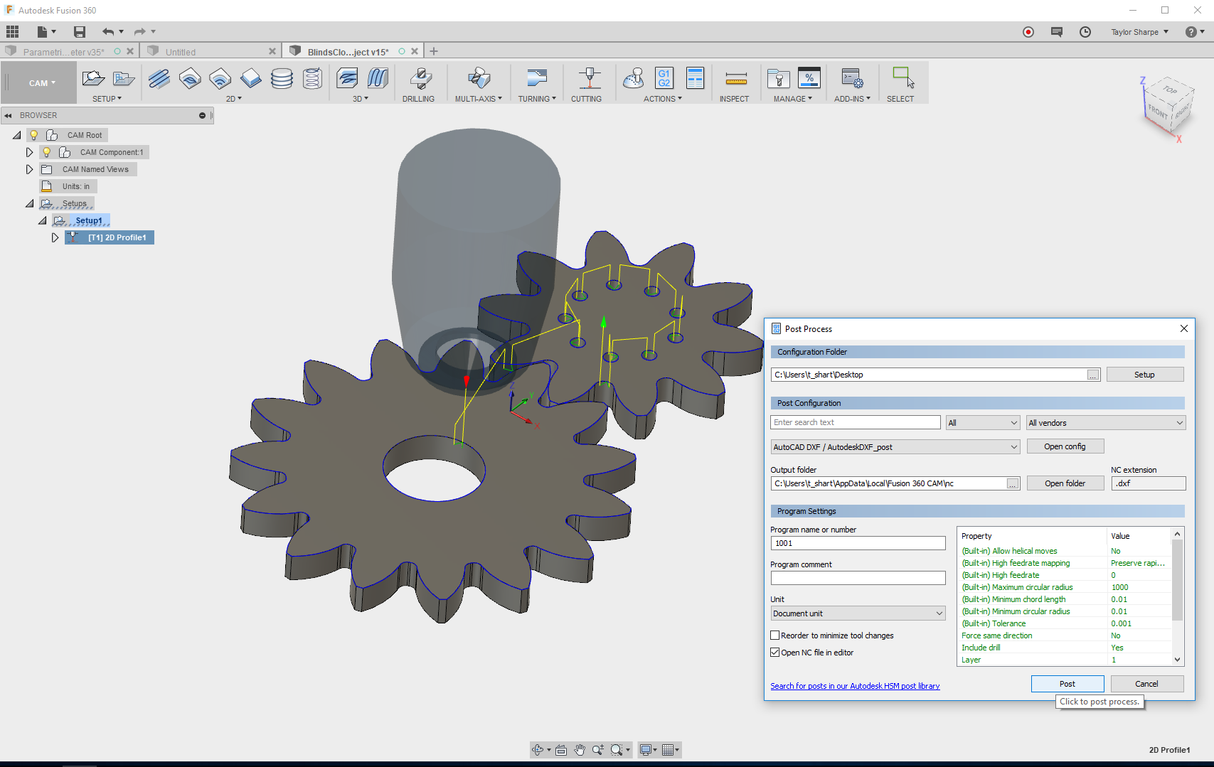
This method takes a little more time, and also requires you to set up your computer for it. But if the other methods fail, this one will usually successfully export a .dxf file with all of the curves in your desired profile.
These files work very well with low-wattage laser cutters, so if you're cutting wood or acrylic, this is usually a good way to go. The files will need significant post-processing after export if you're using a laser that requires lines to be welded together, for example a large production laser used to cut metal parts.
(1) Download one of these post-processors I have also attached them to this Instructable.
a) The Epilog post processor, which outputs your file as an SVG. If you plan to do more post-processing in Inkscape, Illustrator or CorelDRAW, this is a good option.
b) The AUTODESK DXF post processor (found on this page). This just exports a .dxf, and it's the one shown in the screencast.
(2) Put the post-processor in your CAM post library. In the screencast, I just placed the file on my desktop and navigated to it.
(3) Make a simple CAM toolpath using a library lasercutter. The width doesn't matter.
a) You'll need to turn compensation off in the toolpath settings, but you won't have to do much else.
b) Even if you don't have experience with the CAM workspace, just do what I do in the video and you should be fine!
(4) Post your process as if you're preparing an NC file. Choose the Epilog or AUTODESK DXF post-processor, and you'll be provided with a prompt to save your .svg or .dxf file!