Expanding Table

Hi, my name is Ben, and I’m passionate about creating innovative DIY projects. In this Instructable, I’ll show you how I made a compact and functional table using the Fletcher Capstan mechanism.
Inspired by the Make It Move contest, I wanted to design something that had a mesmerizing movement while also providing value and flexibility. After some research, I stumbled upon the ingenious Fletcher Capstan mechanism, which allows a table to expand and contract seamlessly. This unique design is perfect for small spaces and combines both form and function. It also gives you flexibility to have a large or small display table. And it’s really fun to watch it “Transform”!
In this project, I’ll take you through my journey of building my own version of the Fletcher Capstan Table. From initial sketches to 3D printing and assembly, I’ll share all the steps and challenges I faced along the way. Whether you’re a seasoned woodworker or a DIY enthusiast, this project will push your skills and inspire you to think creatively about furniture design.
Join me as I transform a simple idea into a masterpiece that can expand and contract through beautiful movement, making it a versatile addition to any space. Let’s get started!
Supplies
Materials:
- 3D Printer Filament (PLA): For printing the table components.
- 2mm Rods: For the carriage movement.
- 3mm Rods: For the star’s movement.
- Glue: Strong adhesive for securing rods and other components.
Tools:
- Wire Cutters: For cutting the rods to the required length.
- 3D Printer: For printing the table components.
Background
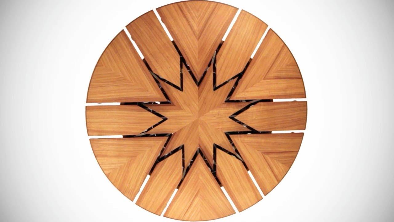
In my quest to create this compact and functional furniture through transformative movement, I found myself pondering the idea of a table. I wanted something that could save space without sacrificing utility. I started thinking of this design when I saw the Make It Move contest. I thought of something that could be small and then enlarge (expand), and I thought of furniture, specifically tables. After some research, I stumbled upon the ingenious Fletcher Capstan mechanism. This unique design allows a table to expand and contract seamlessly, making it perfect for large and small uses.
The Fletcher Capstan Table, designed by David Fletcher, is a marvel of modern carpentry and engineering. It features a round table that can expand to nearly double its size while maintaining its circular shape. This is achieved through a complex mechanism that stores the expansion leaves within the table itself. The table can seat six people in its original form and up to twelve when expanded, making it incredibly versatile for various settings.
Inspired by this concept, I decided to build my own version of the Fletcher Capstan Table. The idea of creating a piece of furniture that combines both form and function was too exciting to pass up. I began by studying the mechanism in detail, understanding how the layers and rotating components work together to achieve the expansion.
For my version, I decided to use 3D printing and metal rods to create the components. This approach allowed me to precisely fabricate the intricate parts needed for the mechanism. The combination of 3D printed parts and metal rods provided the necessary strength and durability while keeping the project accessible for DIY enthusiasts.
Creating my version of this table involved several steps, from designing the components to assembling the mechanism. The process was challenging but incredibly rewarding, and I’m excited to share it with you.
In this Instructable, I’ll show you how I made my own Fletcher Capstan Table using 3D printing and metal rods, and provide detailed instructions so you can create one too. Whether you’re a seasoned woodworker or a DIY enthusiast, this project will push your skills and inspire you to think creatively about furniture design.
Mechanisms
How the Fletcher Capstan Table Works
The Fletcher Capstan Table is a masterpiece of engineering, featuring a complex mechanism that allows it to expand and contract seamlessly. Here’s a detailed look at how it works:
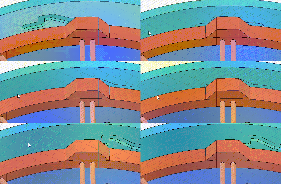
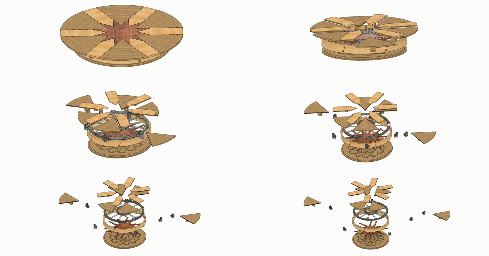
Mechanism 1: Shell Comes Down for Parts to Come Out
The first mechanism involves the outer shell of the table. When you initiate the expansion process, the shell of the table lowers slightly. This action creates space for the internal components to move and prepares the table for the next steps. The lowering of the shell is a crucial step as it ensures that the parts can move freely without any obstruction.
Mechanism 2: Leaves Come Out
Once the shell is lowered, the second mechanism comes into play. This involves the primary leaves of the table, which are stored within the table itself. These leaves slide out from their hidden compartments and align themselves with the existing tabletop. The movement is smooth and precise, thanks to the carefully designed tracks and guides that direct the leaves into place. This mechanism effectively doubles the surface area of the table, making it suitable for accommodating more people.
Mechanism 3: Secondary Leaves and Star/Center Lifts Up
The final mechanism involves the secondary leaves and the central star-shaped component. After the primary leaves are in place, the secondary leaves, which are also stored within the table, come out and fill in the gaps between the primary leaves. Simultaneously, the central star-shaped piece lifts up to align with the rest of the tabletop. This star-shaped component not only adds to the aesthetic appeal of the table but also provides additional stability and support to the expanded surface.
These three mechanisms work in harmony to transform the table from a compact piece of furniture into a larger, more functional one. The precision and ingenuity behind the design make the Fletcher Capstan Table a remarkable example of modern furniture engineering.
Initial and Final Diameter
When designing the Fletcher Capstan Table, the initial diameter of the table is 180 mm, and it expands to a final diameter of 240 mm. This change in size is achieved through the clever use of the table’s mechanisms and the precise alignment of its components.
Initial Diameter: 180 mm
The table starts with a compact diameter of 180 mm. This initial size was chosen because it was easier to print the components at this smaller scale. Printing smaller parts allowed for quicker prototyping and testing, ensuring that the mechanisms worked correctly before scaling up.
Final Diameter: 240 mm
When expanded, the table reaches a diameter of 240 mm. This larger size was selected to maximize the table’s functionality and size. Additionally, the expanded size maintains the table’s structural integrity and aesthetic appeal, ensuring that it remains stable and visually pleasing.
Why the Portions Need to Be the Same
The key to the table’s functionality lies in the uniformity of its portions. Each segment of the table, whether it’s the primary leaves, secondary leaves, or the central star-shaped component, must be precisely the same size and shape. This uniformity ensures that the table expands evenly/smoothly and then contracts hiding all of the parts.
3d Model Notes

There were a few things I made sure my model had:
- Sketches:
- I wanted them fully contained. This means they are locked and can’t be moved or dragged around.
- Imagine drawing a picture and taping it to the table so it doesn’t move. This way, I could edit the sketches a lot without errors happening.
- If a sketch is open, it’s like having a puzzle piece that doesn’t fit. You can’t build on it, and anything depending on that piece becomes a problem.
- Joints/Assemblies:
- These allowed me to simulate the movements.
- Think of it like building a LEGO robot and making sure all the parts move correctly before playing with it.
- This helped me see errors before 3D printing, meaning fewer prototypes and less filament and waste.
- Contact Joints/Assemblies:
- These allowed me to see how parts acted when they touched each other.
- Imagine two gears in a clock. Contact joints help me see how they interact and move together.
- This improved the simulation, making sure everything worked smoothly.
- Section Analysis:
- This allowed me to see inside and through the object.
- It’s like having X-ray vision to look inside a toy to see how it works.
- This helped because in complex systems like this table, I could see inside what was happening and make sure everything was working correctly.
3d Model
To start this design, I opened Fusion 360, a powerful CAD (Computer-Aided Design) software developed by Autodesk. Fusion 360 is an incredible tool that combines industrial and mechanical design, simulation, collaboration, and machining in a single package. It’s widely used by engineers, designers, and hobbyists for creating precise 3D models and prototypes.
Initial Sketch
- Creating the Initial Sketch: I started by creating my first sketch, which defined the initial diameter of 180 mm and the leaves of the table. This sketch served as the foundation for the entire model.
- Segment Division: The circle was divided into equal segments, each representing a ‘leaf’ of the table. This division was crucial for ensuring that the table could expand evenly.
Shell Sketch
- Creating the Shell: I started by offsetting the initial 180mm circle by 5mm to form the outer shell.
- Offset Line: This offset line creates a 5mm thick boundary around the original circle, which will serve as the structural shell for the table.
- Purpose: By offsetting the circle, I defined the thickness of the shell, which is crucial for the table’s stability and durability. This step ensures that the outer shell can support the expanding and contracting mechanisms without compromising the table’s structural integrity.
Extruding Components
- Extruding the Bottom: I started by extruding the bottom part of the table, which would be fixed. This forms the base of the table and provides stability for the entire structure.
- Creating the Shell: Next, I extruded the shell that was defined in the second sketch. This shell is crucial as it houses the mechanisms that allow the table to expand and contract.
Rods/rod holders
- Creating the Insert: I designed an insert for the rods, which is essential for the table’s expanding mechanism.
- Reference Rods: The pink rod in the image serves as a reference for where the actual rods will be placed. This rod is not printed but helps visualize the placement and alignment of the rods.
Sketching the Leaves and Star
- Central Star: The star, colored yellow, is positioned at the center of the table. This star is a crucial component of the table’s expanding mechanism.
- Top Leaf: The first or top leaf is colored pinkish red. This leaf is one of the primary components that expand to increase the table’s surface area.
- Secondary Leaf: The secondary leaf is colored green. This leaf fills in the gaps between the top leaves, ensuring a smooth and continuous surface when the table is expanded.
- Design Purpose: This sketch is essential as it defines the dimensions and positions of the leaves and the star. The precise alignment and sizing are critical for the smooth operation of the table’s expanding mechanism.
Patterning the Rods
- Patterning the Rods: I patterned the rod 12 times around the central hub.
- This patterning is for the 6 top leaves (big) and the 6 secondary leaves (small).
- Symmetry: The symmetrical arrangement ensures that the leaves can expand and contract evenly.
Modeling the Carriage
- 3D Modeling the Carriage: I created the carriage, which is designed to slide along the rods.
- Purpose: This component is crucial as it connects to the leaves and allows them to move smoothly along the rods.
- Cost Consideration: I opted not to use linear bearings to keep the overall cost down. Instead, the carriage serves as a cost-effective solution for the sliding mechanism.
Adding the Notch
- Creating the Notch: I added a notch to the carriage that would slide inside the shell.
- Purpose: The notch acts like a guide, ensuring that the carriage can move smoothly along the shell.
- Sketching the Channel for the Notch:
- Created a channel in the sketch for the notch to slide through.
- This channel will be extruded into the shell.
- Ensures smooth and precise movement of the notch within the shell.
- Critical for the functionality and stability of the expanding and contracting mechanism.
- Extruding the Channel into the Shell:
- The sketched channel is now extruded into the shell.
- This creates a three-dimensional path for the notch to slide through.
- Ensures the notch can move smoothly and precisely within the shell.
- Critical for the stability and functionality of the expanding and contracting mechanism.
Creating the Guide for the Carriage
- Most Important Sketch: I created the most important sketch, which was the guide for the carriage.
- Purpose: This guide ensures that the carriage moves out of the way for the star. As the table expands, the star needs to rise and align with the rest of the table. The guide ensures that the carriage moves in such a way that it doesn’t obstruct the star’s movement.
- Critical Dimensions: The dimensions of this guide are incredibly important. If the angle is too steep, the star will come out too late, disrupting the timing of the expansion. Conversely, if the angle is too shallow, the carriage won’t move smoothly, causing friction and potential jamming.
- Too Much Angle: An excessive angle would delay the star’s emergence, causing it to misalign with the expanding leaves.
- Too Little Angle: An insufficient angle would hinder the carriage’s movement, making it difficult for the mechanism to operate smoothly.
- Design Considerations: To achieve the perfect balance, I carefully calculated the angles and dimensions. The guide needed to be just right to ensure that the carriage could move seamlessly along its path.
- Functionality: As the rods turn, the carriage moves along the guide because of the angle. This movement is essential for the star to rise and align with the table’s surface. The guide ensures that the carriage moves out of the way at the right moment, allowing the star to emerge smoothly.
Star Mechanism
- Star Mechanism: The star mechanism is designed to lift up and down, starting off hidden and then rising through the use of angled ramps.
- Initial Position: The star (yellow) starts in a lowered position, hidden within the table.
- Angled Ramps: The base (blue) features angled ramps that guide the star as it turns. These ramps are crucial for lifting the star smoothly.
- Lifting Process: As the table expands and the rods turn, the star is guided by the angled ramps. This movement causes the star to rise and align with the rest of the table.
- Smooth Operation: The precise angles of the ramps ensure that the star lifts smoothly and at the right time. Too steep an angle would not lift the star, while too shallow an angle would take too long for the star to lift
Lifting the Secondary Leaves
- Creating the Lifting Mechanism: I designed a part that would lift the secondary leaves as the star lifts up.
- Star and Leaves Interaction: The star (yellow) is central to the mechanism, and as it lifts, it engages with the secondary leaves (green).
- Lifting Process: The secondary leaves are positioned in between the primary leaves (pinkish red). As the star rises, it pushes the secondary leaves upward, ensuring they align with the primary leaves.
- Smooth Operation: The design ensures that the secondary leaves lift smoothly and at the right time, maintaining the table’s structural integrity and aesthetic appeal.
- Purpose: By designing this lifting mechanism, I ensured that the secondary leaves would rise in sync with the star, contributing to the seamless expansion of the table.
- Sketching the Guide for the Secondary Leaves:
- Created a guide for the bottom leaf that needs to slide out and then lift up.
- The guide ensures smooth sliding and lifting with the rod.
- This guide will be extruded into the shell.
- Critical for the functionality and stability of the expanding and contracting mechanism.
Sketching the Rod Placement for the Star
- Creating the Sketch: I sketched the placement for the rods that would go into the star. This step is crucial for ensuring that the star can both spin and lift.
- Star Mechanism: The star (yellow) needs to spin and lift as part of the table’s expanding mechanism.
- Rod Function: The rods are designed to fix the star in place while allowing it to move up and down. This ensures that the star can rotate smoothly without any wobbling.
- Purpose: By designing this rod placement, I ensured that the star could spin and lift efficiently, contributing to the smooth operation of the table’s expanding mechanism.
Downloads
Animate/render
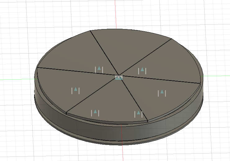
Animating the Model in Fusion 360:
Now that I had the model done, it was time to animate it. I started off with the visualization.
- Visualization:
- Visualization is like coloring in a drawing to make it look real. It helps us see what the final product will look like.
- In Fusion 360, visualization means adding colors, textures, and materials to the model. I chose different types of wood for the table. Imagine picking out different colors and textures for your LEGO bricks to make your creation look just right.
Once the woods were done, I moved to animation.
- Animation:
- Animation is like making a flipbook where each page shows a part of the story. When you flip through the pages quickly, it looks like the picture is moving.
- In Fusion 360, animation means making the parts of the model move to show how they work together.
- To achieve this, we must transition from the Design tab to the Animation tab.

To animate, I used different types of movements.
- First Mechanism - Shell Coming Down:
- I started by showing the movement of the first mechanism, which is the shell coming down.
- To do this, I used the transform/move tool. This tool moves parts a certain amount of degrees in a given time.
- For example, if I want the shell to rotate 60 degrees and move down 5mm, I can set it to do this in a specific time.
- Imagine if the shell rotates 60 degrees in 5 seconds, it means it moves 12 degrees per second (60 degrees ÷ 5 seconds = 12 degrees per second).
- Additionally, it moves down 5mm, like sliding a drawer down a little bit while it rotates.
I used that same tool to move out all of the leaves.
- Linear Movement:
- Linear movement is like sliding a drawer in and out. It moves in a straight line.
- I used the transform tool to move the leaves outwards in a straight line.
Lastly, I moved the star and secondary leaves up.
- Final Touches:
- I did some last touch-ups to make it look good, like adjusting camera angles and time smoothing. This is like setting up a camera to take the best picture and making sure the transitions between movements are smooth.
- Explode Tool:
- The explode tool is like taking apart a LEGO model to show all the different pieces. It “explodes” the model, showing how all the parts fit together.
- In Fusion 360, using the explode tool helps us see each component separately, making it easier to understand how everything works. This ended up with the animation you can see here:
Prototype 3d Printing
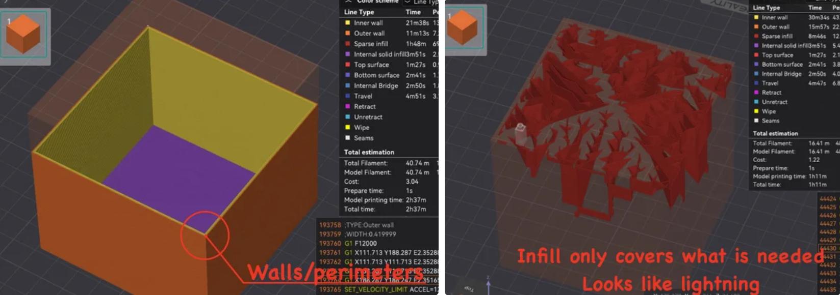
Prototype 3D Printing:
With our model ready, it was time to start printing. The first print is like a practice run, so I use what I call “prototype settings” to save time and material.
- Layer Height:
- Imagine building a tower with LEGO bricks. If each brick is very thin, it takes a lot of bricks to make a tall tower. But if we use thicker bricks, we need fewer bricks to reach the same height.
- For example, if our model is 24mm tall and each layer is 0.12mm, it would take 200 layers. By doubling the layer height to 0.24mm, we only need 100 layers, making it much faster!
- Wall Thickness (Perimeters):
- Think of the walls of a house. The outer walls protect everything inside. By making these walls thinner or using fewer of them, we save material and print faster, but the house might not be as strong.
- These walls are the outermost layers of our print. Reducing the number of walls or making them thinner saves filament and speeds up the print, though it might make the print less sturdy.
- Infill:
- Imagine a chocolate bar with a honeycomb pattern inside. The honeycomb gives it strength without using too much chocolate.
- Infill is the internal structure that supports the print. Without any infill, the print would be too weak, so we need just enough to keep it stable.
- Lightning Infill:
- This infill pattern only adds material where it’s needed, like lightning bolts. It provides support while using minimal filament, making it perfect for prototypes.
These adjustments help create a prototype that prints quickly, uses minimal filament, and still serves its purpose.
Problems with My Model:
Unfortunately, there can be many problems with a model. The more complex it gets, the harder it is to get everything right.
- Tolerances:
- Think of tolerances like the space between puzzle pieces. If the pieces are too tight, they won’t fit together. If they’re too loose, they fall apart.
- Friction:
- Friction is like rubbing your hands together. Too much friction can make parts stick, while too little can make them slide too easily.
- Guide Rails:
- The guide rails for the carriage to move in and out were either too steep or not steep enough, causing them to either not move or come out too quickly.
- Star Mechanism:
- The star required a change because the angle was too steep, making it difficult to function properly.
Assembly
- Prepare the Secondary Leaf and Carriage:
- Begin by taking the secondary leaf (the smaller one) and its corresponding carriage.
- Attach a small rod to the carriage. This rod will act as a pin in the slider mechanism.
- Attach Rods to the Star:
- Cut the rods to a length of approximately 7mm.
- Carefully glue each rod into the designated slots on the star component. Ensure that the rods are straight and securely attached.
- Insert Rods into the 3D Printed Frame:
- Place the rods into the 3D printed frame, aligning them with the appropriate slots.
- Insert the Star:
- Insert the star through the center of the frame, ensuring it fits snugly and aligns with the rods.
- Insert the Leaves:
- Carefully insert the leaves into the 3D printed frame, guiding them through the rods. Ensure that each leaf is properly aligned and can move smoothly.
- Secure the Rods:
- Glue the rods into the frame to prevent them from falling out. Make sure the glue is applied evenly and the rods are firmly in place.
- Attach the Bottom Plate:
- Finally, attach the bottom plate (main body) to the assembly. Ensure it is securely fastened and aligned with the rest of the components.
- Final Check:
- Verify that the table can expand and contract smoothly. Make any necessary adjustments to ensure all parts move correctly.
You now have a functional table that can expand and contract seamlessly. Enjoy your new piece of innovative furniture!
Next Step Forward
Overall, this was a unique project I worked on. It ended up not being as smooth as I wanted. I think that’s due to a few reasons:
- All 3D Printed:
- Imagine building a toy car entirely out of LEGO bricks. Sometimes, the wheels might wobble because the pieces don’t fit perfectly together.
- In my project, everything was 3D printed, including the rods. This caused some wobbling because the parts didn’t fit as tightly as they should.
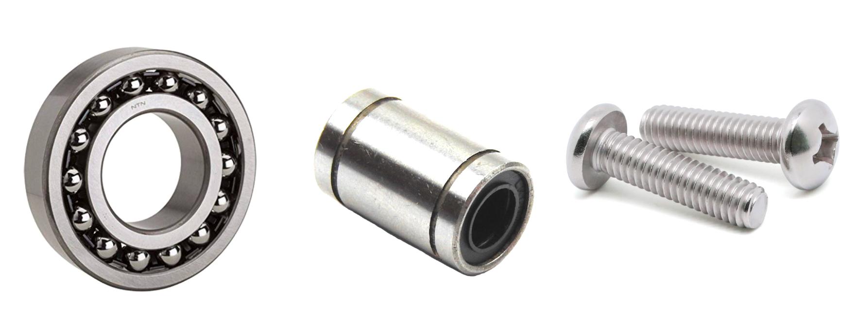
- To fix this, I would use manufactured parts like ball bearings and linear bearings. These are like using real car wheels instead of LEGO wheels—they fit better and move more smoothly.
- Too Much Friction:
- Friction is like when you rub your hands together. If there’s too much friction, it becomes hard to move your hands smoothly.
- In my project, there was too much friction, making it hard for the table to expand and contract.
- To fix this, I would use manufactured parts. These parts are designed to reduce friction, like using a well-oiled hinge on a door so it opens and closes easily.
Overall, if I were to make Version 2, I would incorporate manufactured parts like ball bearings, linear bearings, and screws for accurate alignment.
- Ball Bearings:
- Think of ball bearings like tiny marbles inside a ring. They help parts move smoothly by reducing friction.
- Using ball bearings would make the table’s movement smoother, like how a skateboard rolls easily because of the bearings in its wheels.
- Linear Bearings:
- Linear bearings are like sliding a drawer in and out. They help parts move in a straight line without wobbling.
- Using linear bearings would ensure the table expands and contracts smoothly, like how a drawer opens and closes without getting stuck.
- Screws for Accurate Alignment:
- Screws are like the glue that holds everything together. They make sure parts stay in the right place.
- Using screws would keep everything aligned perfectly, like how screws hold a bookshelf together so it doesn’t wobble
Conclusion

When you think of a table, you usually think of something static, and unmoving. This project takes that static object and “makes it move” in an exciting way to increase the table’s functionality. Overall, this was a fun project to make. It was definitely the most complex Fusion 360 project I’ve ever done. I had to work with multiple moving parts, model their interaction, then bring it to reality and overcome the real world problems! I found out making things moves in conjunction with each other is a lot harder in real life than on the computer!
- Complex Joint Assemblies:
- I learned how to make complex joint assemblies and have them all interact with each other in intricate ways. It’s like making sure all the gears in a clock work together to tell time. I had worked with basic movements before, but this project elevated my skills.
- Animating and Rendering:
- I learned how to animate and render my design, making it look like a real, moving table. I want to continue to grow this skill to improve sharing what the actual result can look like.
Overall, I plan on recreating this project with manufactured components.
- Manufactured Components:
- These are parts made in factories, like ball bearings and screws, which fit together perfectly with much better precision.
- Using these parts will make the table work even better, like using real car parts instead of LEGO pieces for a smoother ride. 3d printed components printed on a budget can only be so precise!
Huge thanks, and I hope I taught you something, whether that was complex assemblies or constrained sketches or general problem solving!


