Esp8266 and Blynk 2.0
Hi, Friends
We know The Arduino IDE and Blynk IO have both been updated to version 2.0.
Unfortunately, most of the tutorials and YouTube videos are outdated. I'm instructing the new version (2.0) here.
so we can easily connect our esp8266 with Blynk 2.0.
Supplies
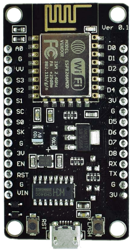

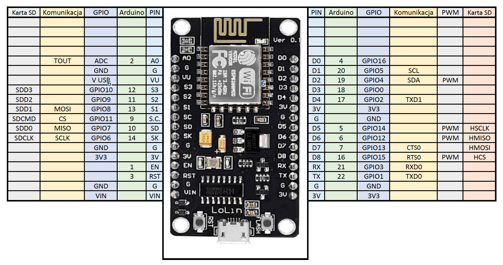
- NodeMCU esp8266 - 1
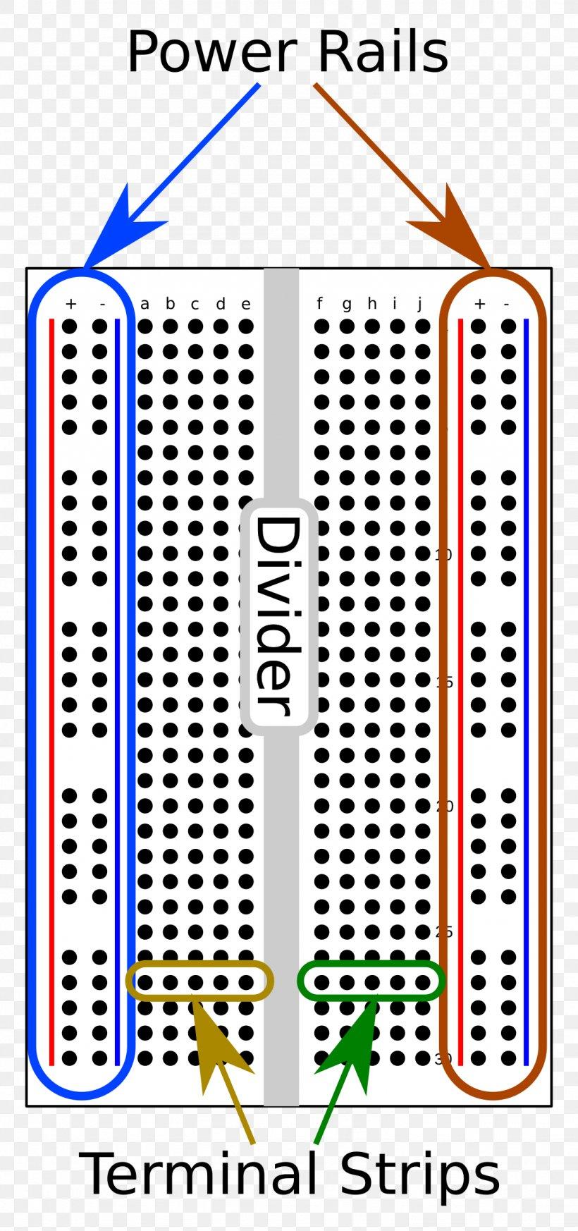
- BreadBoard - 1
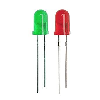
- LEDs , RED LED -1 , GREEN LED -1
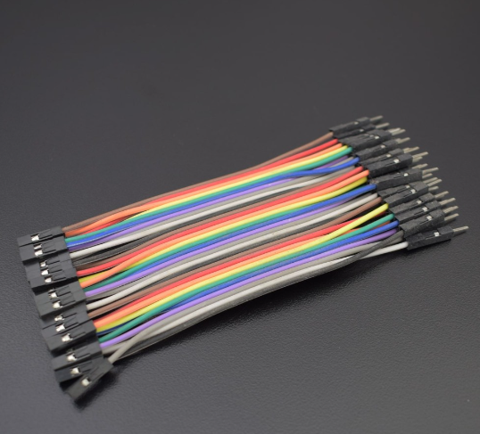
- Jumper Wires - Male to Female
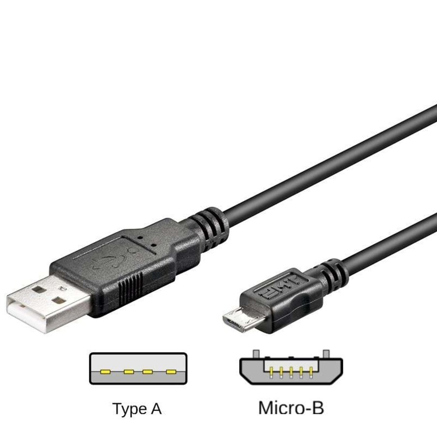
- Data Cable - Mini USB - Type B
Setup Blynk 2.0
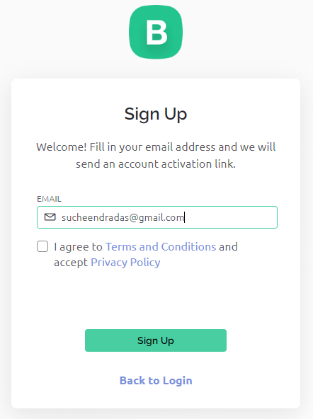
If You Don't Have The Blynk 2.0 Account First Need To create Blynk Account.
Click The Link to Create an account : Register
Okey , i Think You have Created An Account using Your email ,please Note That Don't Forgot your blynk Password
Setup New Template and Add DataStreams
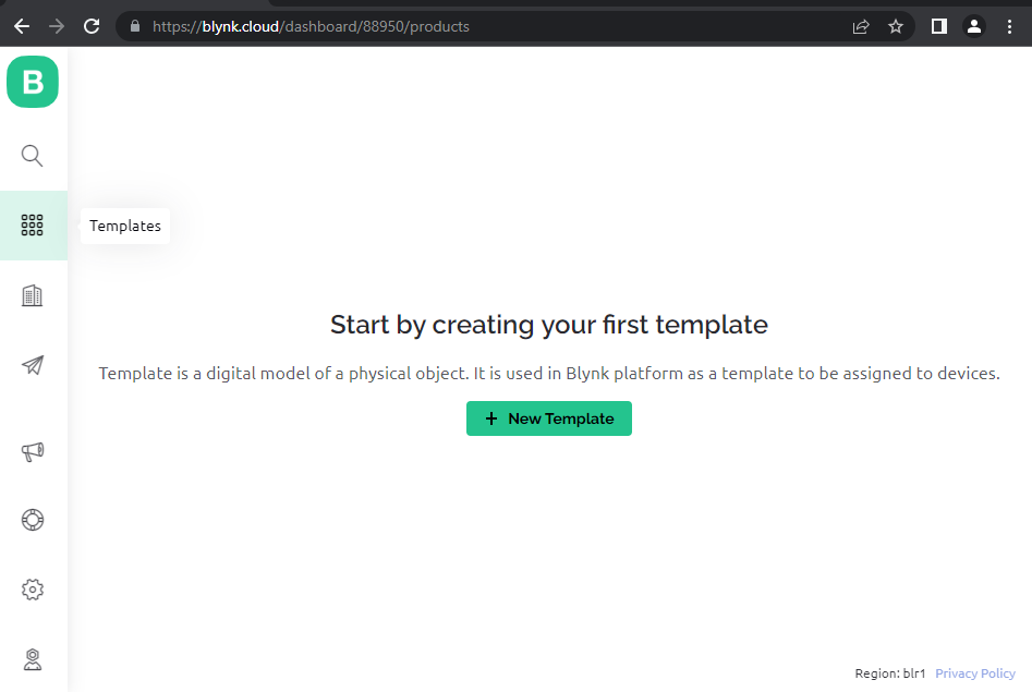
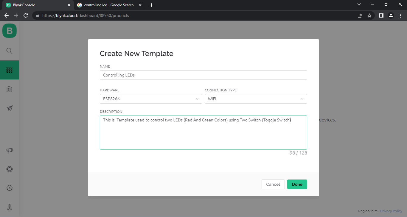
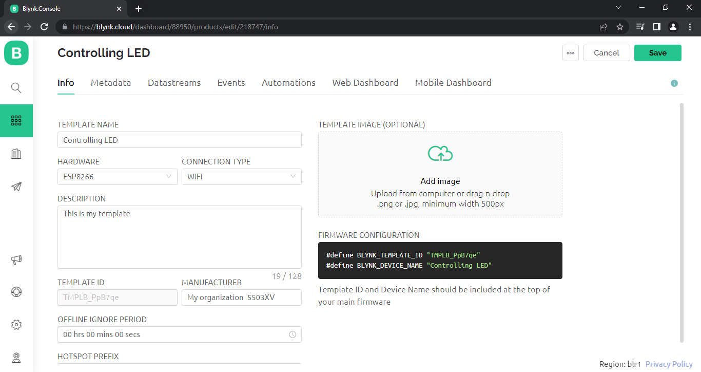
- Click New Template
- type fields as shown above
- Name : Controlling LED
- HARDWARE : ESP8266
- CONNECTION TYPE : WIFI
- DESCRIPTION : Controlling Red and Green Led Via Blynk switch
- Click Done.
Create DataStreams
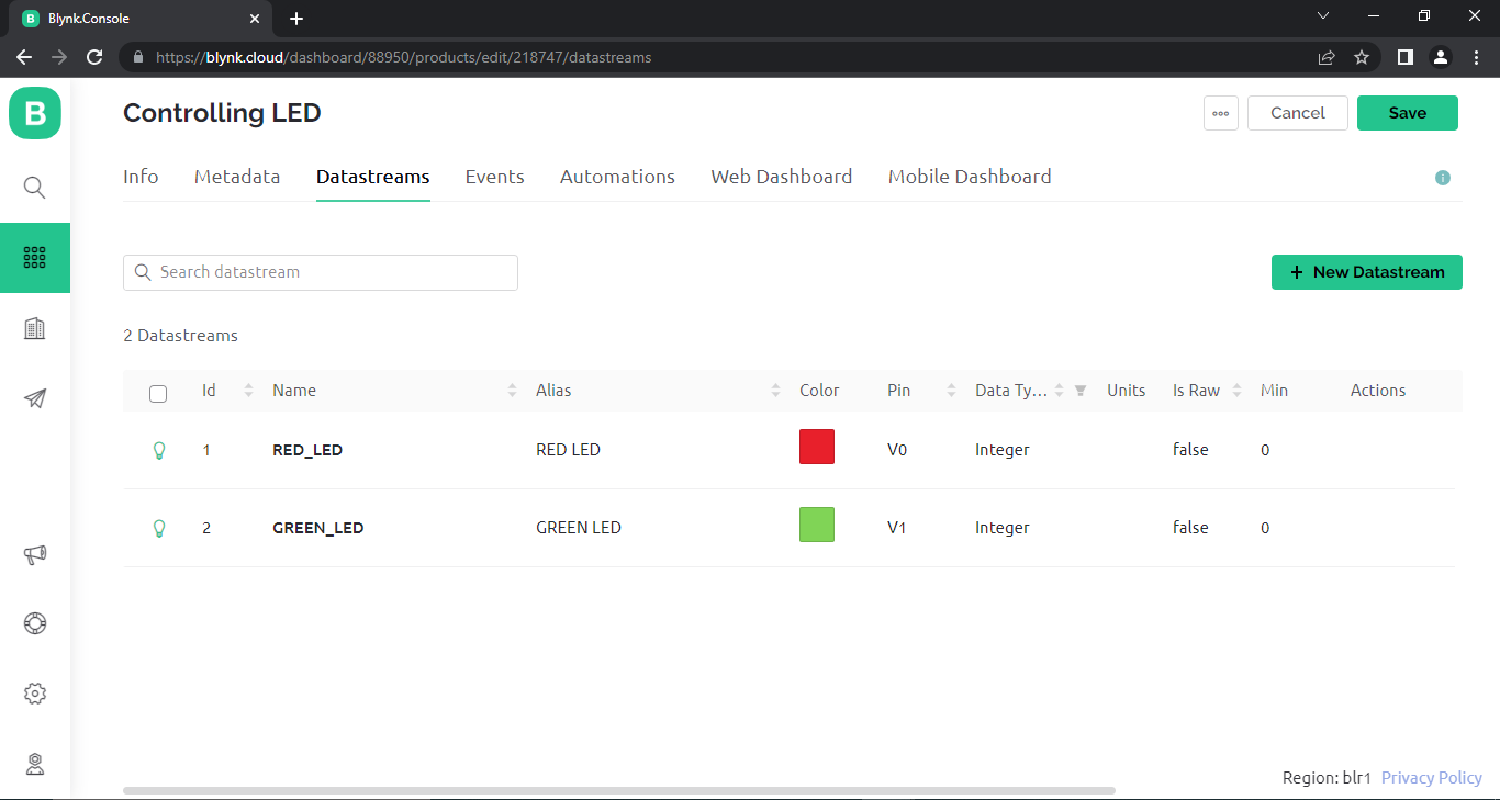
Datastreams: channels for any time-stamped data that flows in and out from the device to the cloud. For example sensor data should go through a Datastream. If you used the first version of Blynk platform, these are Virtual Pins.
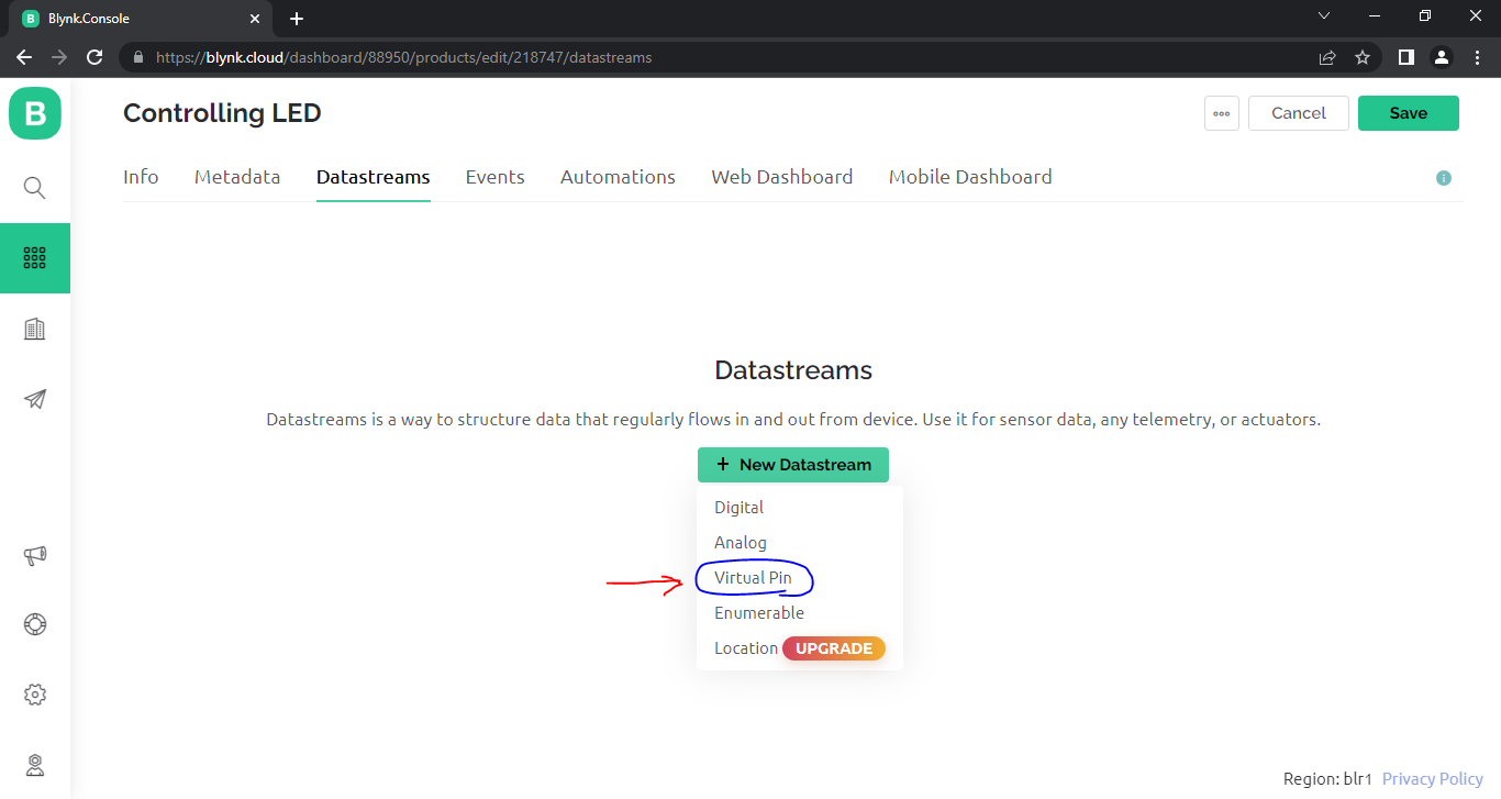
- Click DataStream .
- Click on "New DataStream". Button
- Select Virtual pin
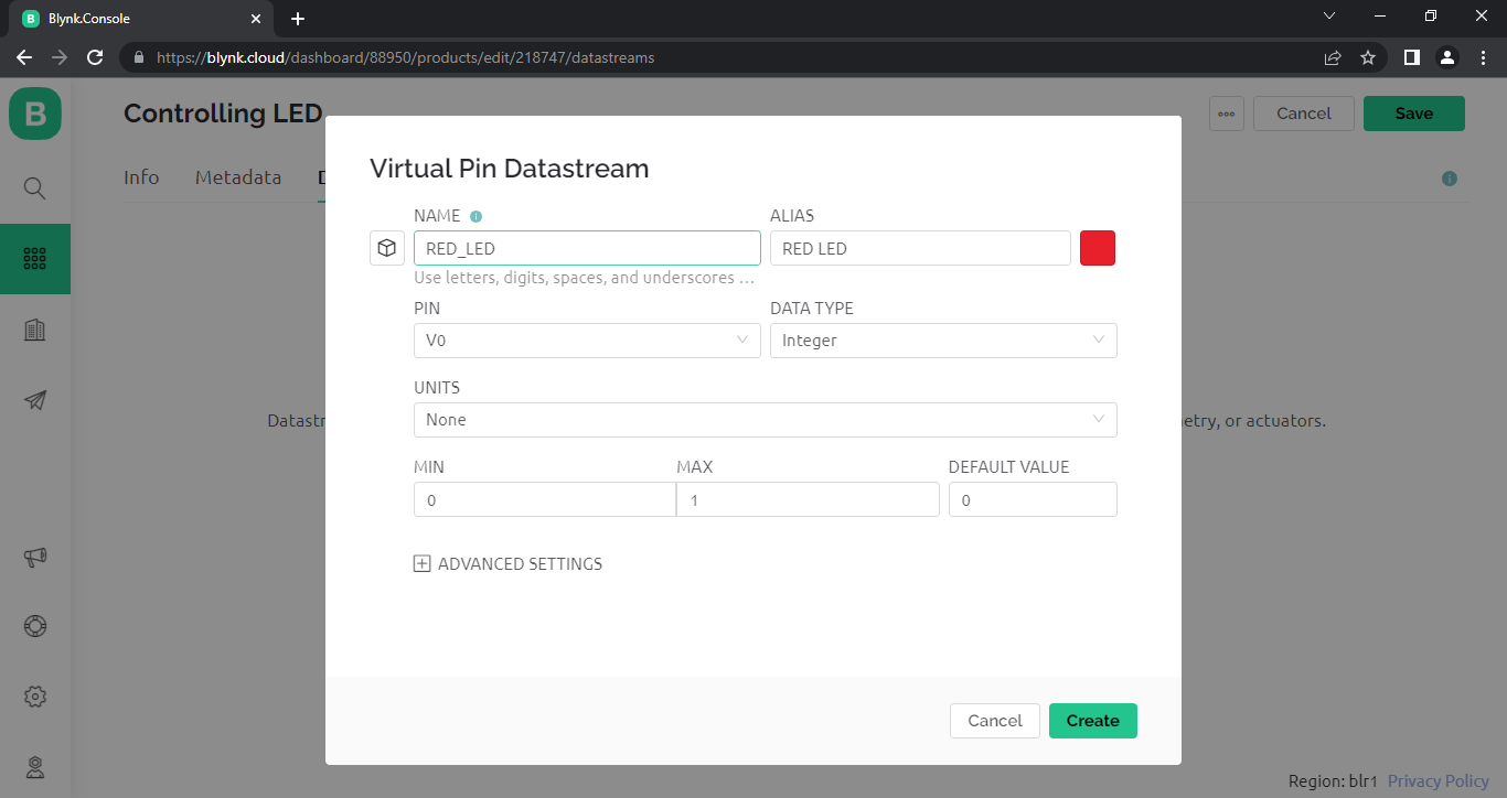
- fill the fields as
- For RED LED
- ICON : BULB
- NAME : RED_LED
- ALIAS : RED_LED
- COLOR : RED
- PIN : V0
- DATA TYPE : integer
- UNITS : None
- MIN : 0
- MAX : 1
- DEFAULT VALUE : 0
5.Click Create Button.
6.Again Click on "New DataStream". Button
7.Select Virtual pin
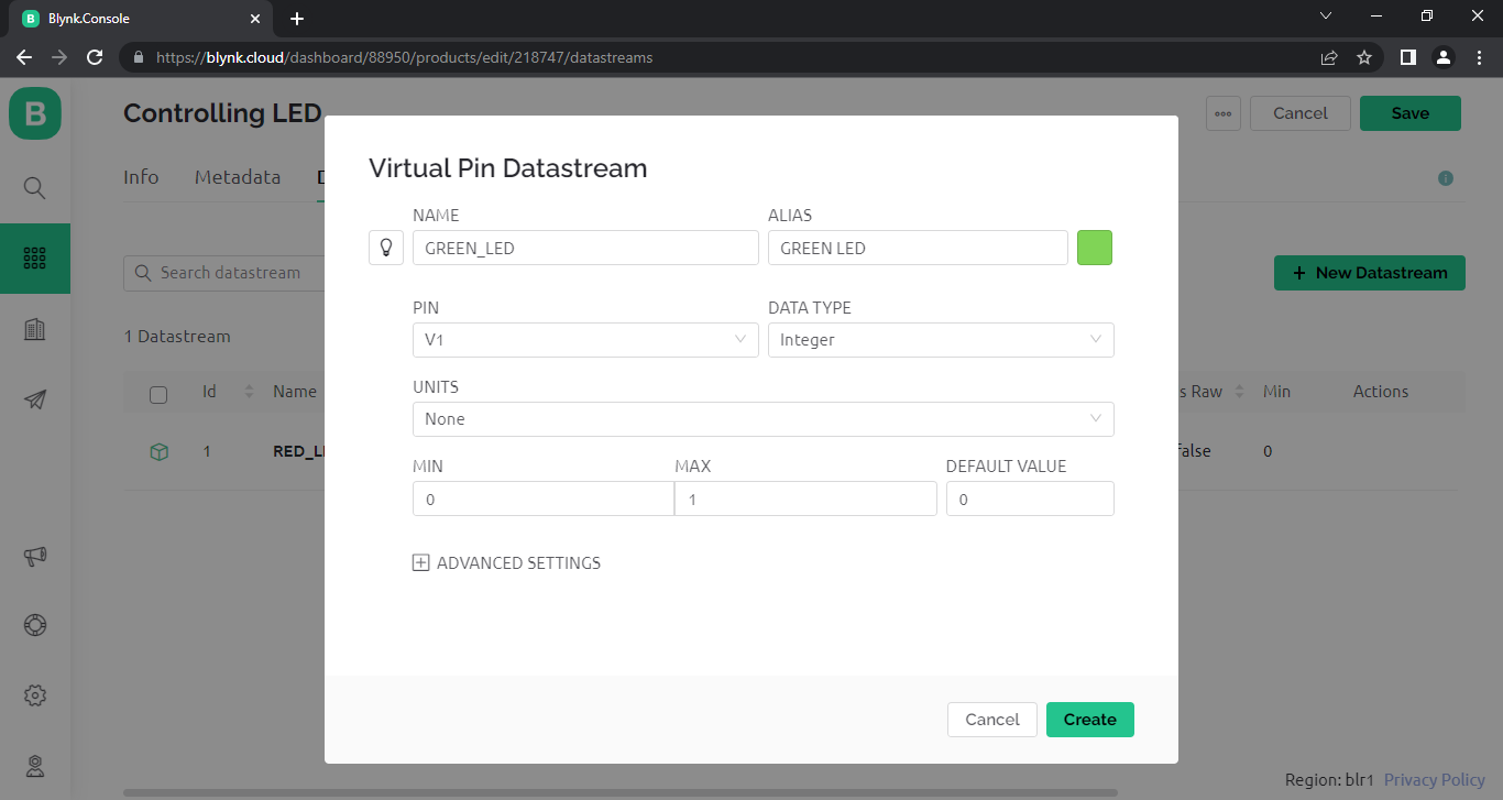
8.fill the fields as
- For GREEN LED
- ICON : BULB
- NAME : GREEN_LED
- ALIAS : GREEN_LED
- COLOR : GREEN
- PIN : V1
- DATA TYPE : integer
- UNITS : None
- MIN : 0
- MAX : 1
- DEFAULT VALUE : 0
9.Click Create
Now You Can See our Datastream list as shown in above figure
Create Web DashBoard Canvas
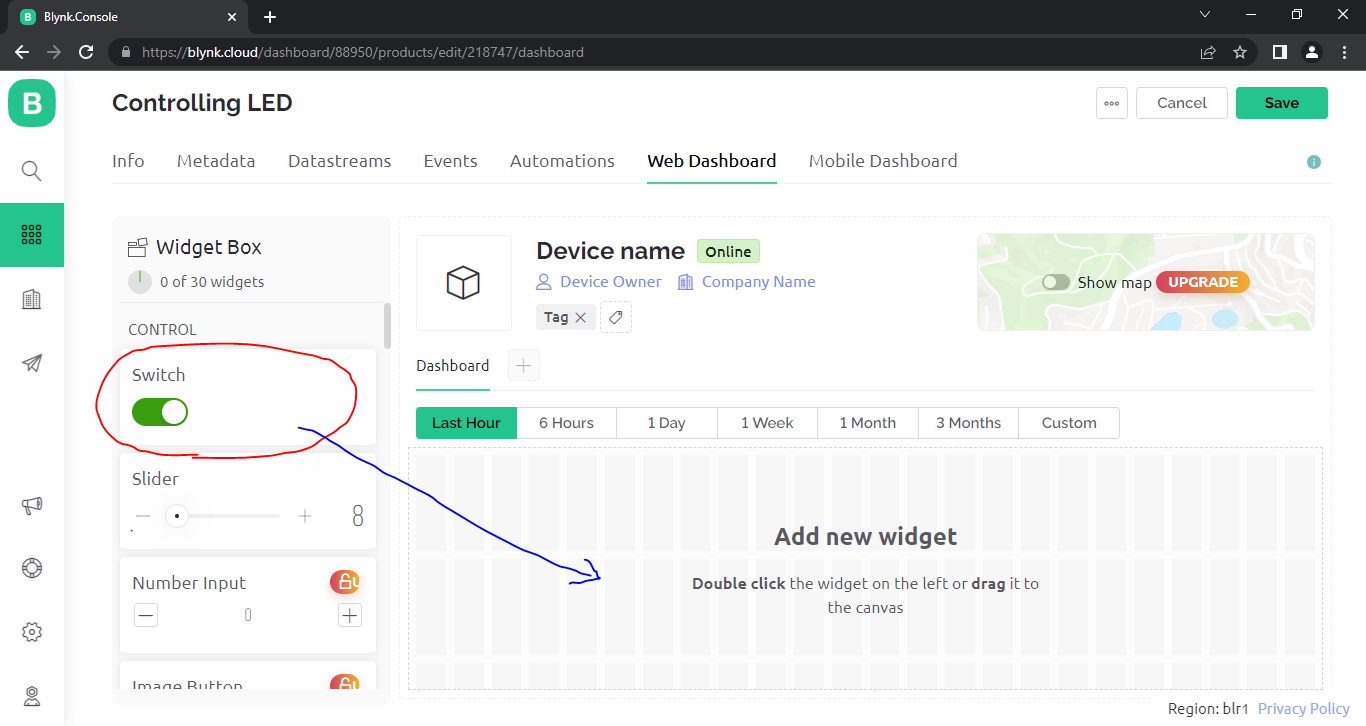
After Creating DataStream our Next Goal to Create a Web Dashboard
- Click the Web dashboard.
- You Can see the widget box on left side
- Under the "CONTROL" Section , you can see Switch Widget.
- select and drag that widget to Canvas at the center
- drag two switches one for RED_LED and One for GREEN_LED
Setup Switches With Datastreams
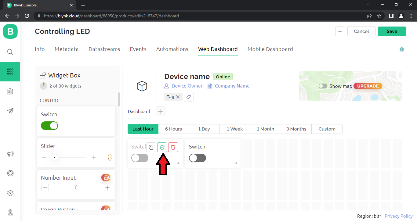
After Dragging two switches on Canvas, we need to integrate Switches With corresponding DataStreams.
- move Mouse pointer on the FIRST switch widget on canvas.
- Select Settings icon (Gear shape).
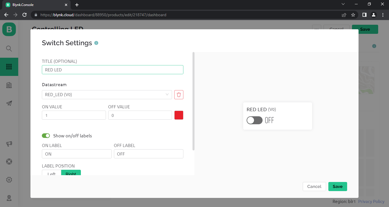
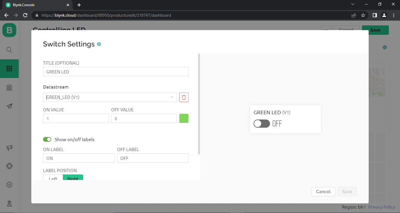
- Now a window will open with Heading" Switch Settings"
- Enter Values as Given Below FOR RED_LED
- TITLE (OPTIONAL) : RED_LED
- Datastream : RED_LED(V0)
- ON VALUE : 1
- OFF VALUE : 0
- COLOR : RED
- show on/off labels
- ON LABEL : ON
- OFF LABEL : OFF
- click save
- move Mouse pointer on the SECOND switch widget on canvas
- Enter Values as Given Below FOR GREEN_LED
- TITLE (OPTIONAL) : GREEN_LED
- Datastream : GREEN_LED(V1)
- ON VALUE : 1
- OFF VALUE : 0
- COLOR : RED
- show on/off labels
- ON LABEL : ON
- OFF LABEL : OFF
- Click Save
- Now Our web DashBoard Completed.
Setup Switches in Android Phone
How to create mobile dashboard?
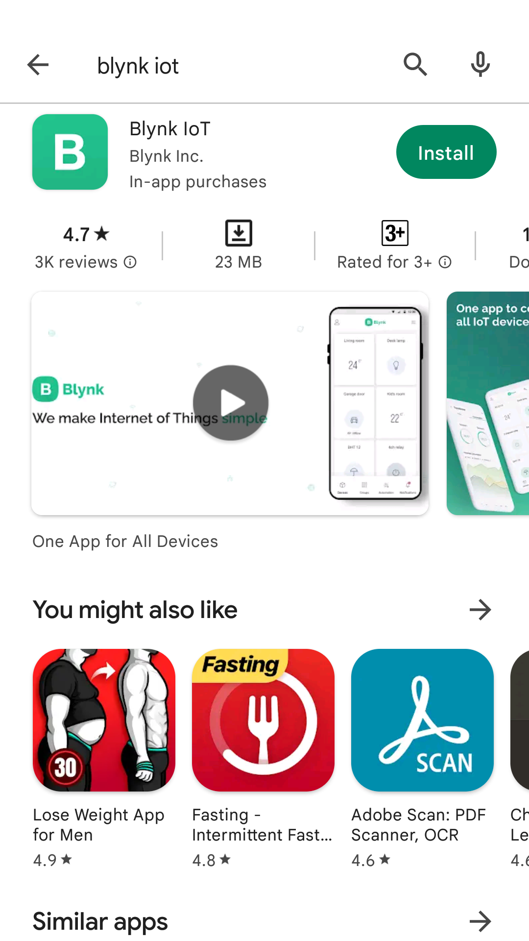
- Open google Play Store App on android phone
- type Blynk IOT on search bar
- you can see Blynk lOT app Developed by Blynk Inc or scan this QR code :Link
- Click install Button
- wait to completed installation
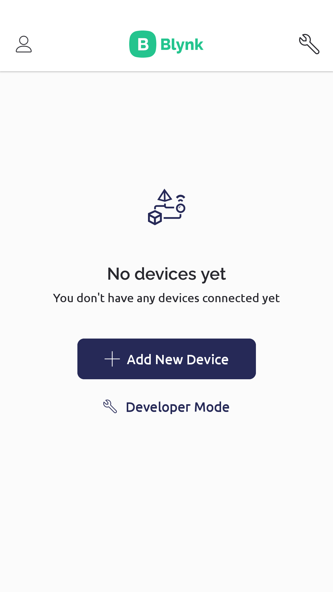
- Open Blynk.App
- Log In to your account (using same email and password)
- Switch to Developer Mode ( spanner icon at the top)
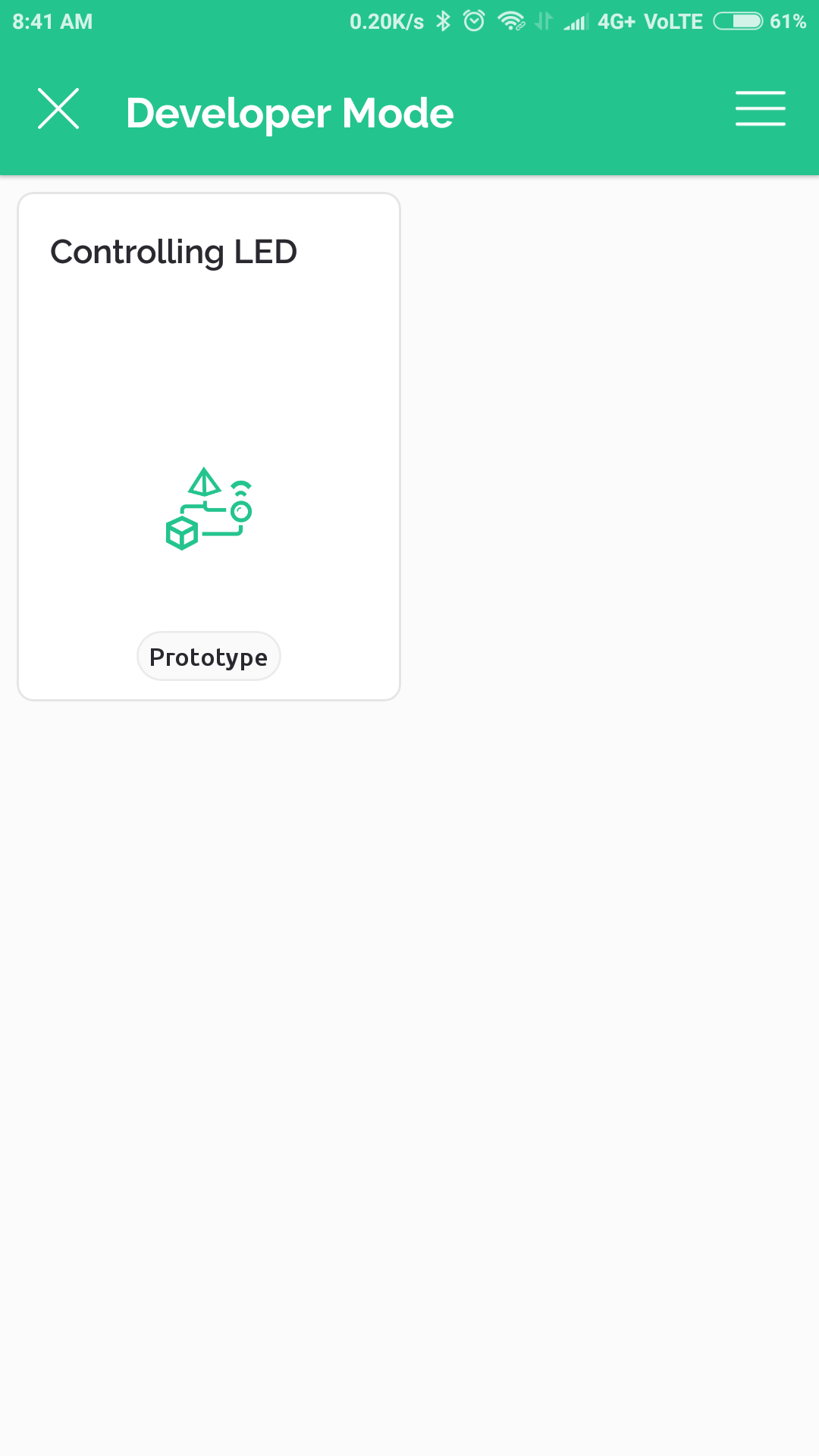
- Find the Controlling LED template we created on the web tap on it
- Tap on "Controlling LED" template (this template automatically comes because we created it on we dashboard).
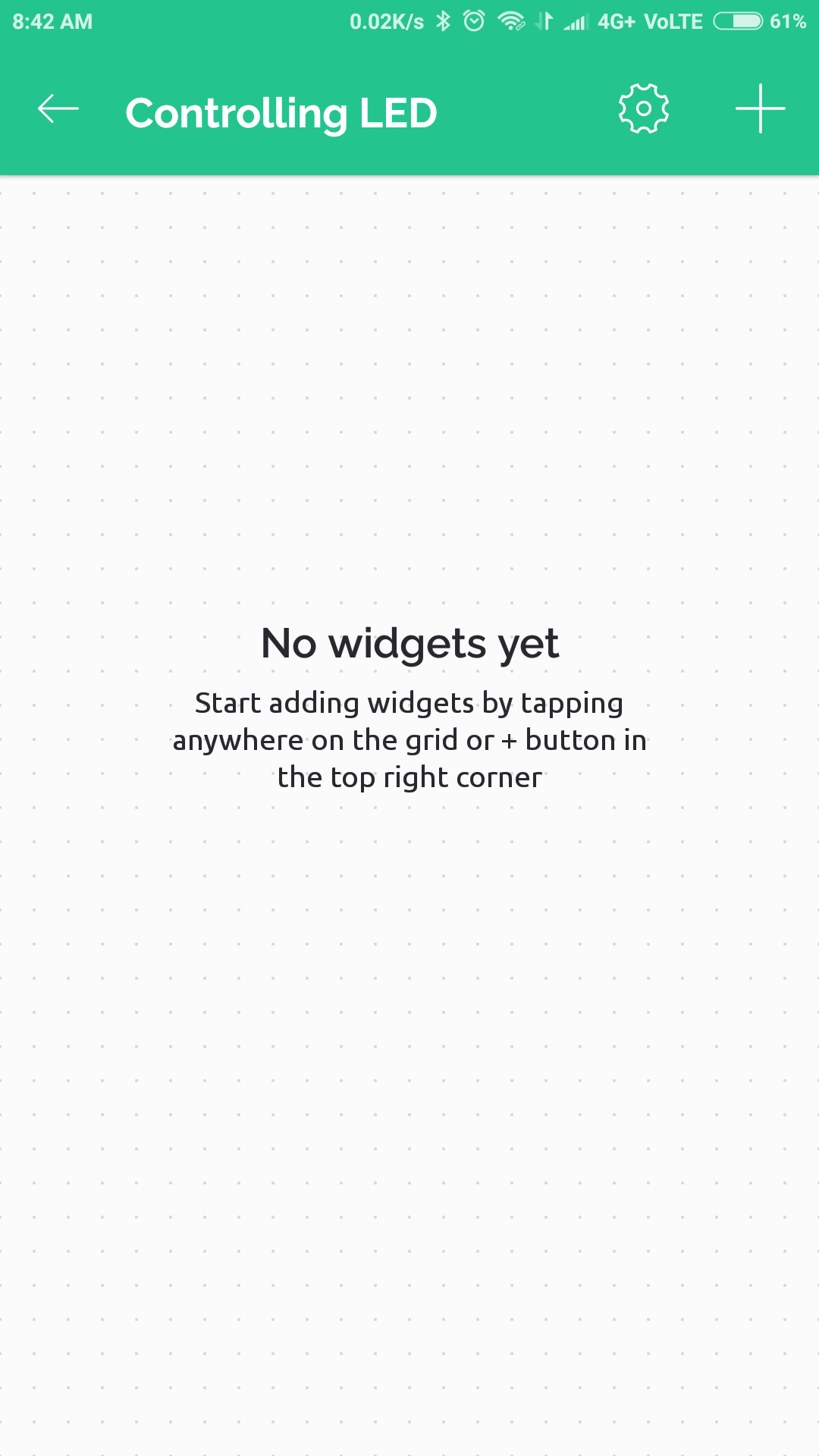
- now you can see an empty canvas with no widget (web widgets and mobile widgets are different).
- you can see plus icon on left right side of the window
- tap on that plus icon
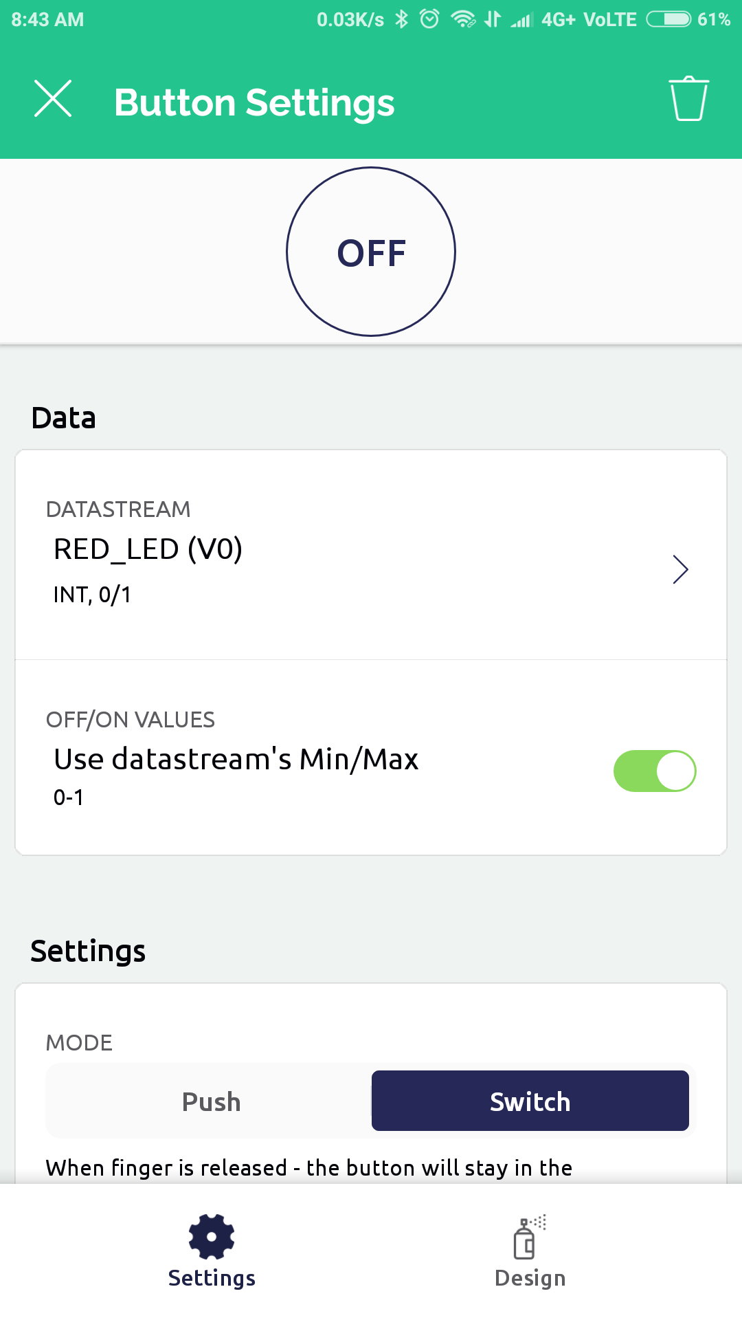
- add Two buttons, one for RED LED and one for GREEN LED
- tap on first button and set Datastream RED_LED(V0) ,
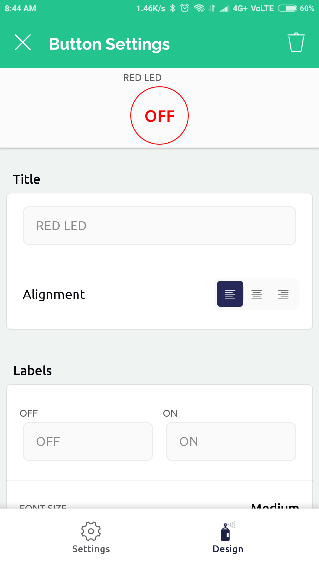
- Change Name and color at design
- tap on second button and set Datastream GREEN_LED(V1) ,
- Change Name and color at design
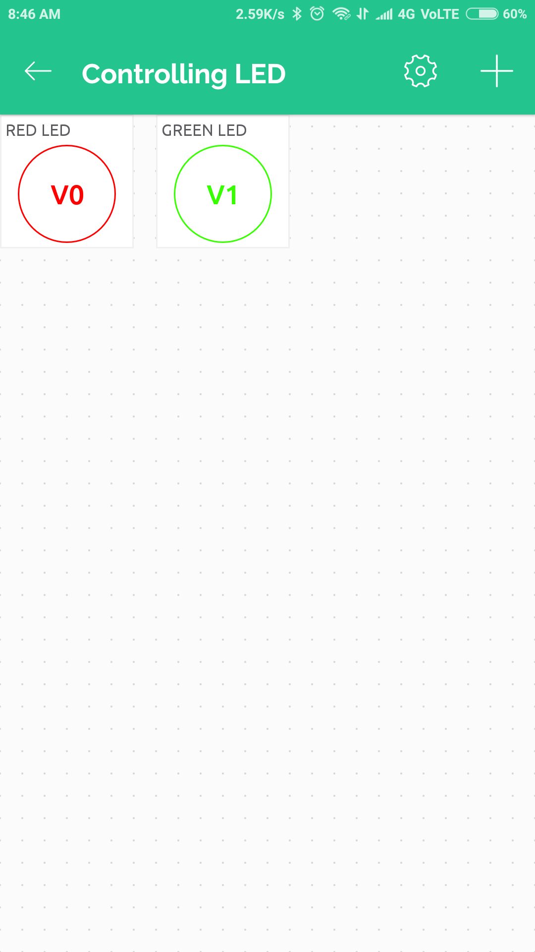
- Now We Successfully Created android template
- it will work similar as web dashboard template
.
Create Device on Bylnk 2.o
- we can create devices from template , so we can create more than one devices working with same template
- here we creating device with name "esp8266" (You can give any name depending upon the device , for example heater, Fan ,Bulb etc).
- following steps are to make "esp8266" Device from "Controlling LED"template.
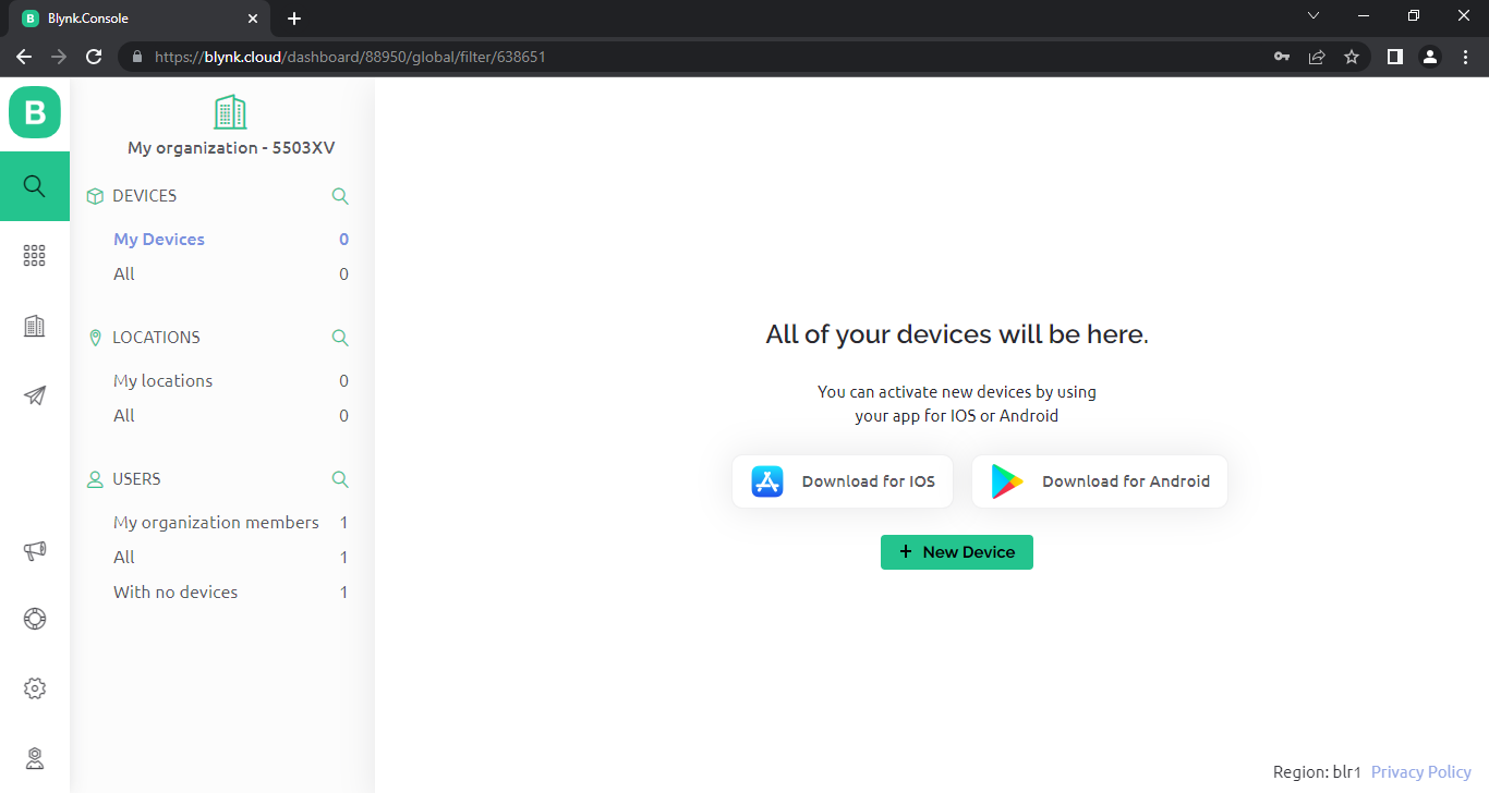
- Click search icon ( lense icon ) on left panel.
- Click to + New Device Button.
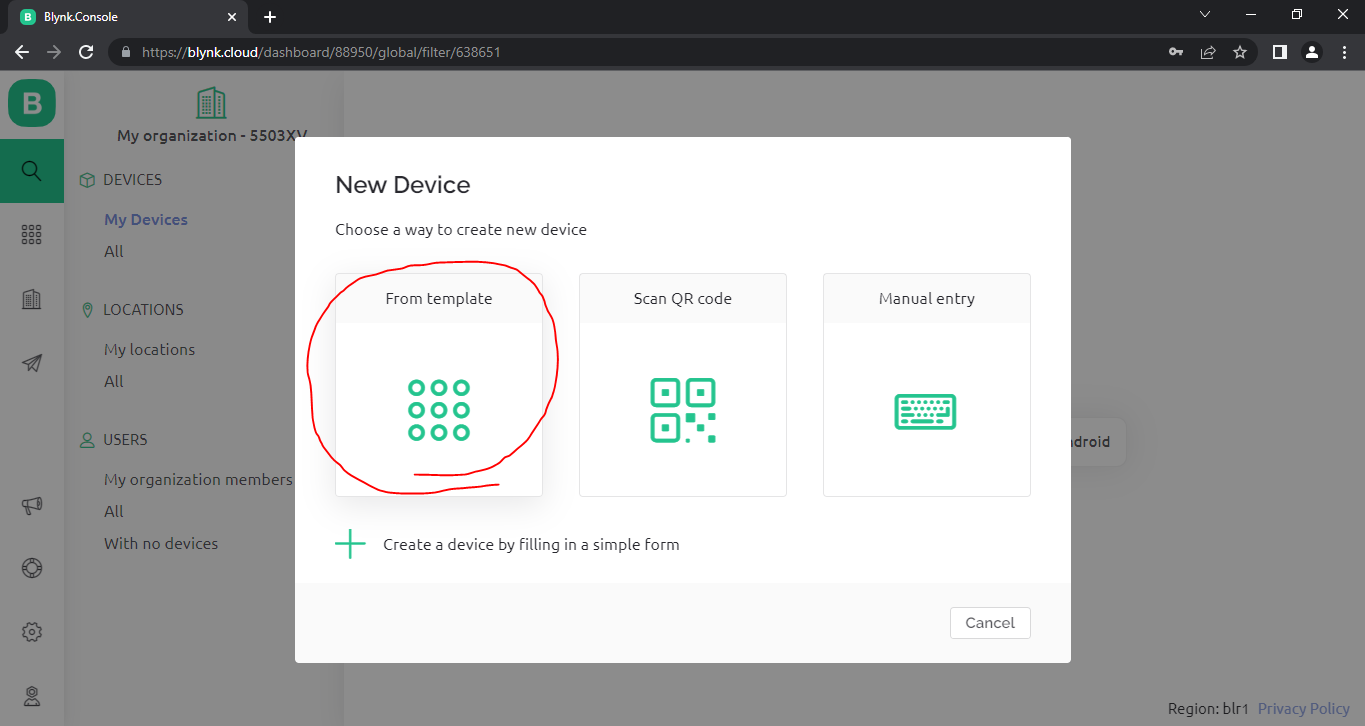
- Now New window will open as shown above image with Name New device.
- click "From template" Button.
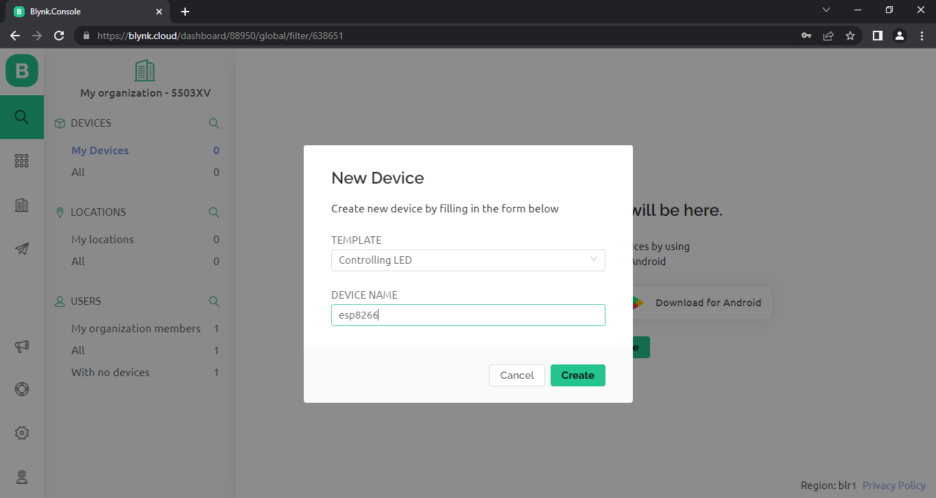
- now a window will come as shown in above image.
- Select Controlling LED template from dropdown TEMPLATE.
- Enter DEVICE NAME to "esp8266".
- click "Create"
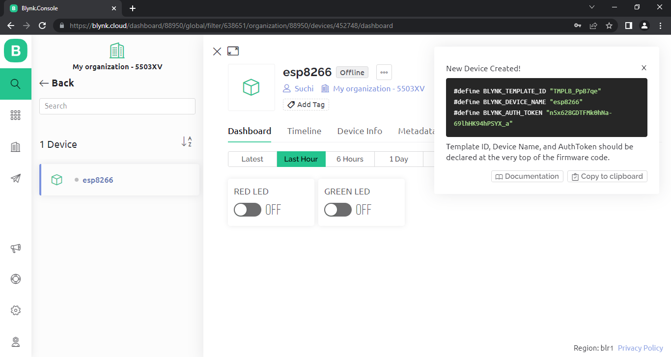
- now new device created , we will get three import items
- Template ID
- Device Name
- AuthToken
13.we can copy this code or we will get this from device info menu item (please read important note )
Important Note : in device info menu item , BLYNK_DEVICE_NAME is "Controlling LED"
but if you want to work our device please give BLYNK_DEVICE_NAME is "esp8266".
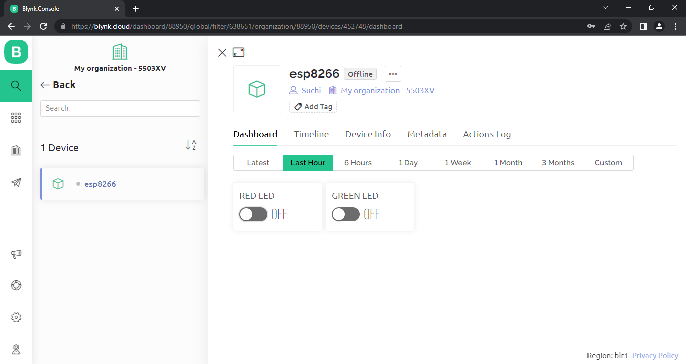
14.click on dashboard to view device's working dashboard, here we an toggle Switch button, but currently it is offline
because we didn't setup esp8266 hardware physically.
Install Arduino IDE , Install Esp8266 Board and Blynk Library
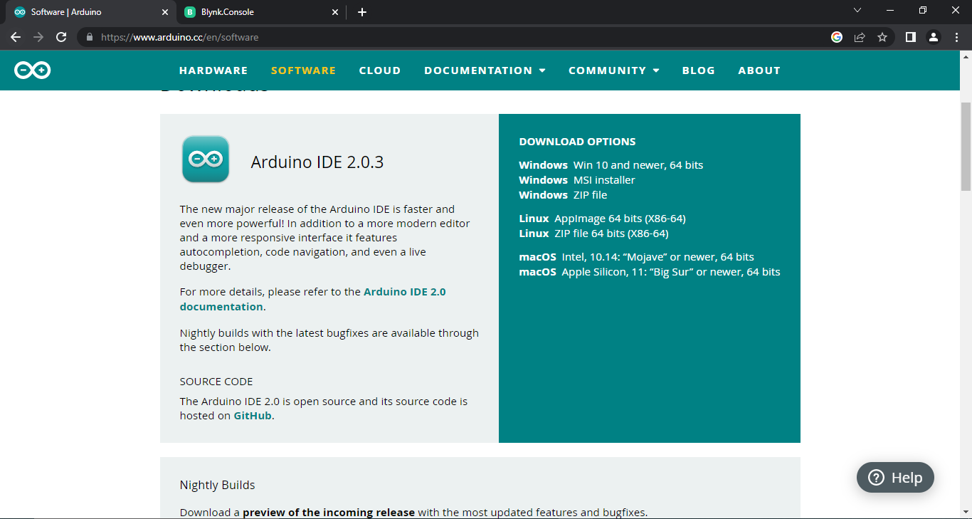
Download And Install Latest IDE - Click Here to Download IDE.
automatic updations of library will come after install IDE
driver installation popup menu will come at that time , please give yes to all popups
Add esp8266 Board to Arduino IDE.
Open arduino ide
First We Need To Install esp8266 Board To Arduino IDE.
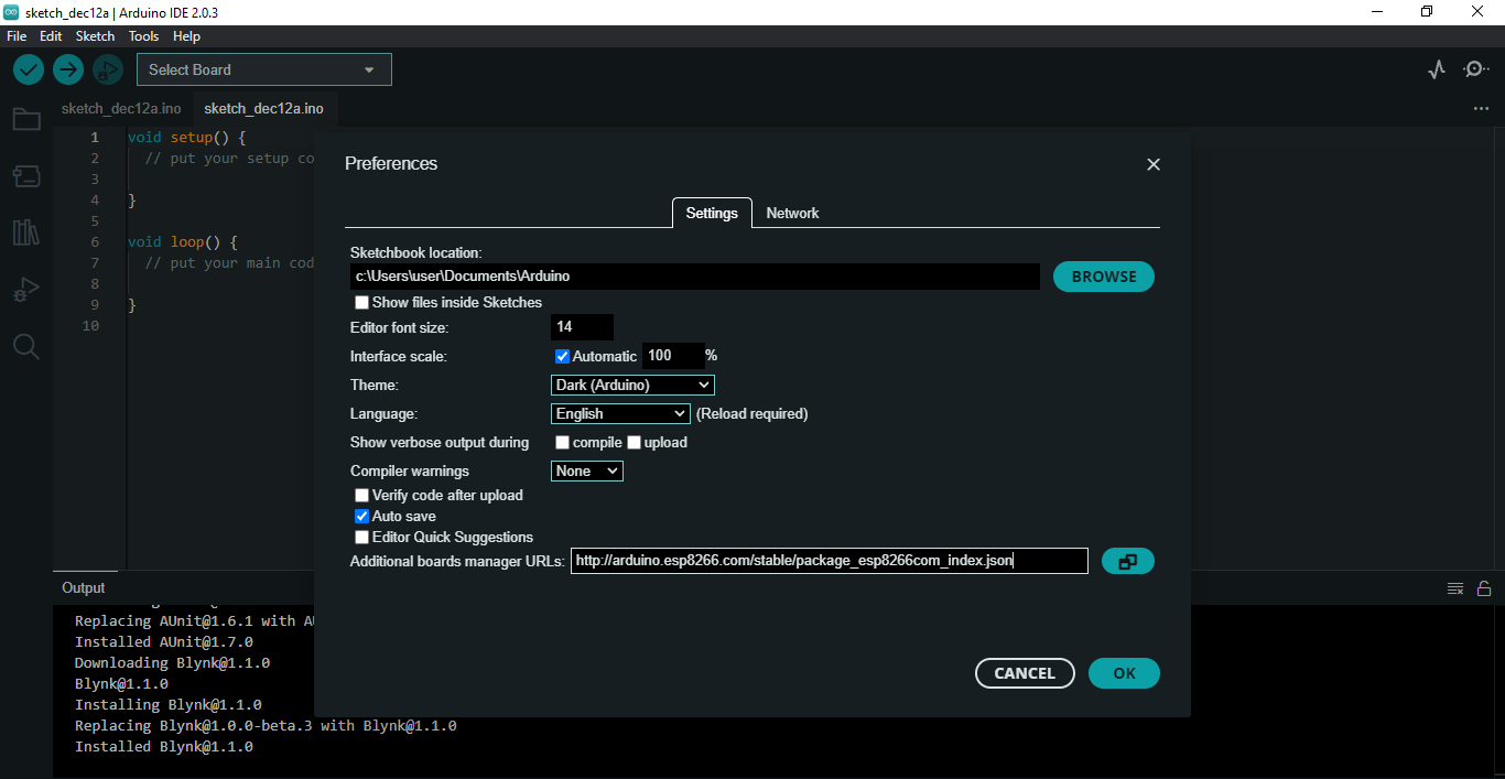
Click File -> Preference. , a Window will open now
Paste http link on Additional Boards Manager URLs : http://arduino.esp8266.com/stable/package_esp8266com_index.json
Click OK , that window will close.
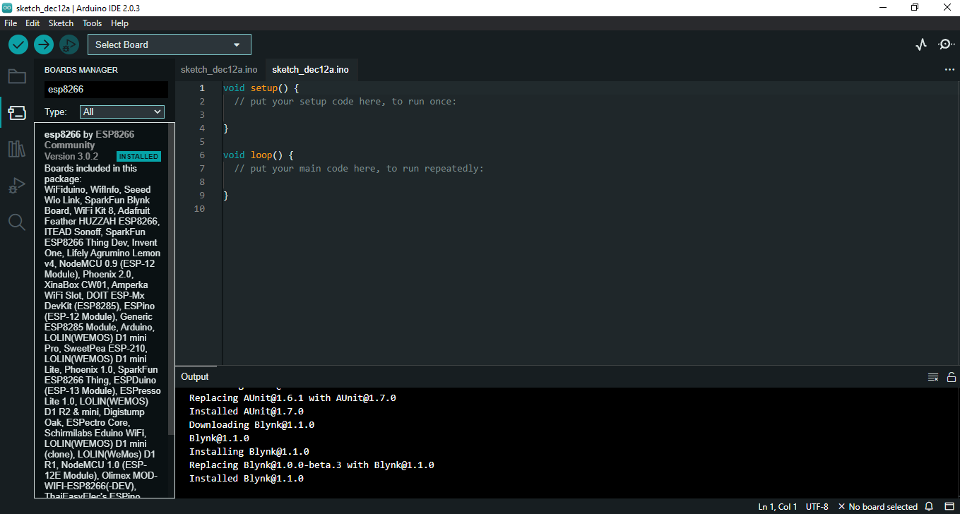
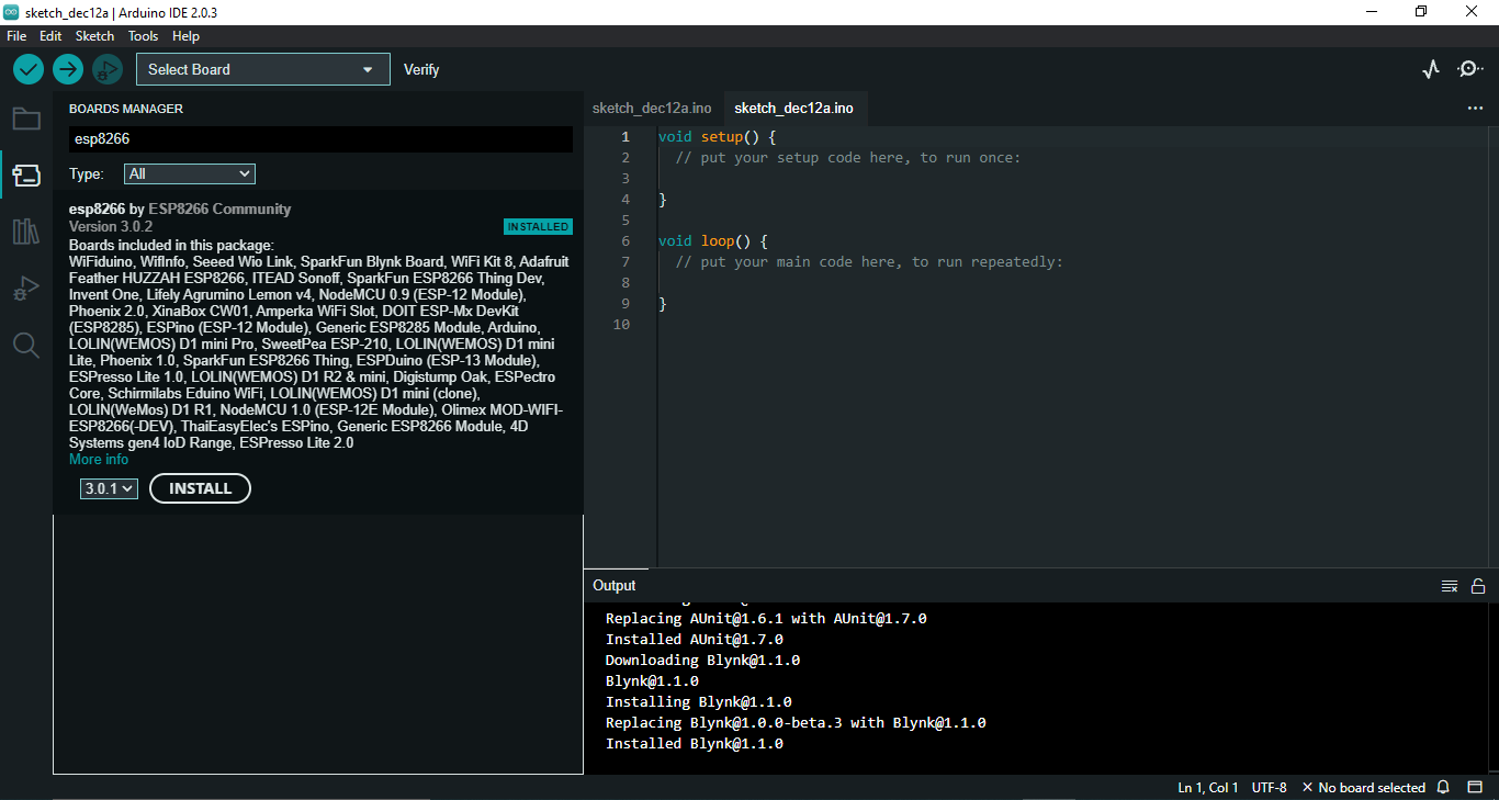
From Menu Tools -> Boards: -> Boards Manger...
type "esp8266" on search bar
Some time You Cant see the install Button , just slide panel left as shown in above image
click install Button.
Now Wait some time to complete the downloading and install esp8266 library
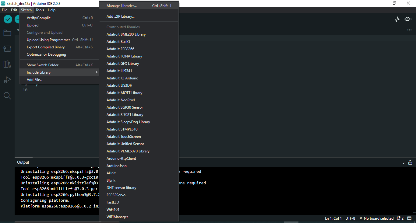
Next, we need to install Blynk Library to Arduino IDE
Click Sketch --> Include Library -- > Manage Libraries
Now You Can see a window
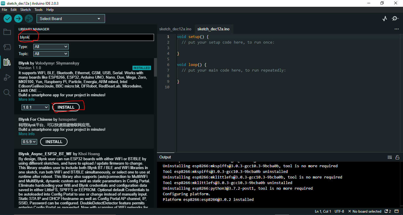
Search Blynk .
now You can see Blynk Library By volodymyr shymanskyy
click Install Button.
Now We installed Board And Blynk Library to Arduino IDE.
Connect Esp8266 Board to Computer
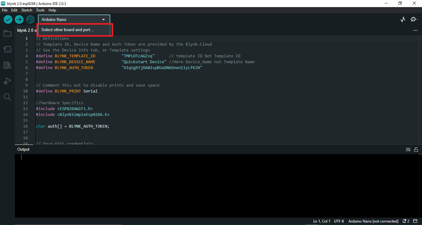
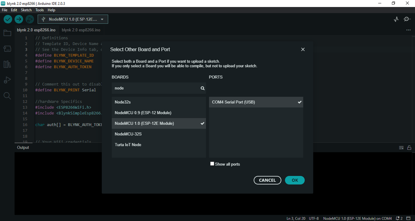
connect Our esp8266 Board to you computer
Select select other board and ports as Shown in above image.
now you can see port "COM" with Unknown Device.(example : "unknown Device on COM4 )
We need to Select Our Board Manually
then select on Unknown COM[]
now a new window will open with heading select other board and ports
Type "node" keyword on BOARDS search.
select NodeMCU 1.0 (ESP-12E Module)
Then Click OK button.
Now our NodeMCU esp8266 Successfully connected with Our Computer
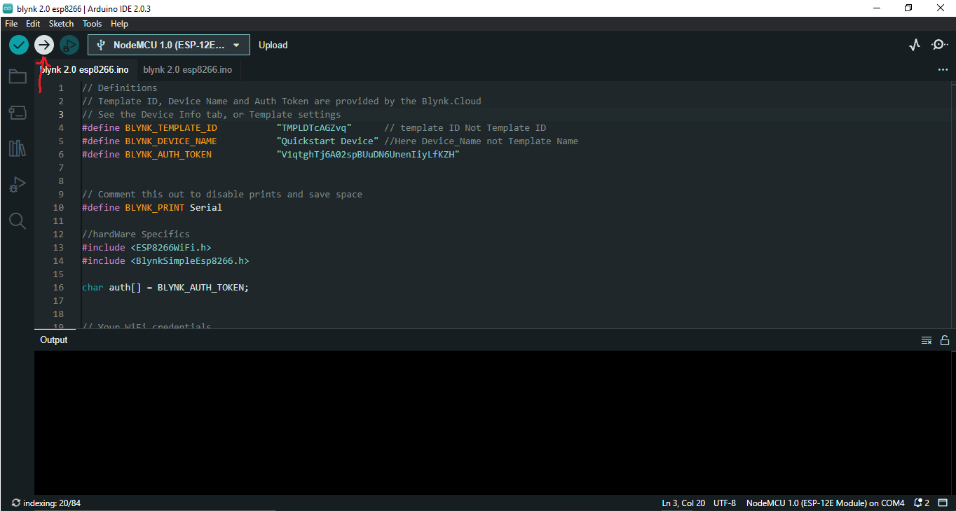
Arduino Code
Hi, i wrote a arduino Code Corresponding to our Dashboard.
I Commented almost all Lines to understand the meaning of each line
Please try to understand the code , if any confusion please sent message.
Github Link - Click Here
Uploading Code to Esp8266
You have two method to bring code to arduino IDE
- Download Ino file from github and click to open.
- copy the code to new sketch (file --> new Sketch )
If you Got Code Then Click Upload Button.
Now Our Work almost finished.
Connect LEDs to Esp8266
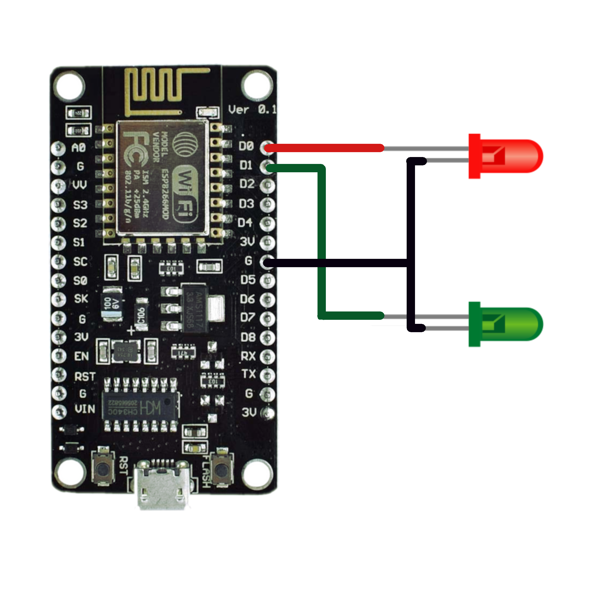
Connect RED and GREEN LED to the esp8266 Board Physically
Wire the circuit Using Above figure
Preform the Project
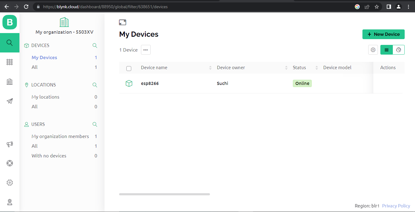
Now go to Blynk Website and select our Device "esp8266"
you can see our device comes Online
Click on esp8266 Device .
now you can see our web dashboard
you can change state of button from ON to OFF and OFF to ON
You can also change states of Button in our Blynk IOT app.
Please watch the above video to understand the working of this project